Advertisement
Quick Links
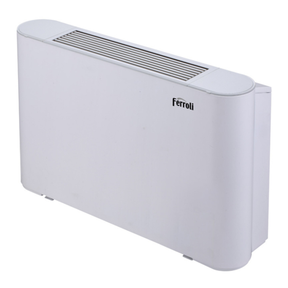
JOLLY TOP
•
I-VM VENTILCONVETTORE CON MOTORE INVERTER PER INSTALLAZIONE A VISTA / FANCOIL WITH DC INVERTER MOTOR FOR
EXPOSED INSTALLATION / FANCOIL TIPO MUEBLE CON MOTOR INVERTER / VENTILO-CONVECTEUR DE TYPE MEUBLE AVEC MOTEUR
INVERSEUR / VENTILOCOVECTOR TIPO MÓVEL COM MOTOR INVERTER
•
I-VN VENTILCONVETTORE CON MOTORE INVERTER PER INSTALLAZIONE CANALIZZATA / FANCOIL WITH DC INVERTER MOTOR
FOR DUCTED INSTALLATION / FANCOIL TIPO CONDUCTO CON MOTOR INVERTER / VENTILO-CONVECTEUR GAINABLE AVEC MO-
TEUR INVERSEUR / VENTILOCOVECTOR TIPO CONDUTA COM MOTOR INVERTER
•
3V-VM VENTILCONVETTORE CON MOTORE A 3 VELOCITÀ PER INSTALLAZIONE A VISTA / FANCOIL WITH 3-SPEEDS MOTOR FOR
EXPOSED INSTALLATION / FANCOIL TIPO MUEBLE CON SELECTOR DE 3 VELOCIDADES / VENTILO-CONVECTEUR TYPE MEUBLE AVEC
MOTEUR À 3 VITESSES / VENTILOCOVECTOR TIPO MÓVEL COM SELECTOR DE 3 VELOCIDADES
•
3V-VN VENTILCONVETTORE CON MOTORE A 3 VELOCITÀ PER INSTALLAZIONE CANALIZZATA / FANCOIL WITH 3-SPEEDS MOTOR
FOR DUCTED INSTALLATION / FANCOIL TIPO CONDUCTO CON SELECTOR DE 3 VELOCIDADES / VENTILO-CONVECTEUR GAINABLE
AVEC MOTEUR À 3 VITESSES / VENTILOCOVECTOR TIPO CONDUTA COM SELECTOR DE 3 VELOCIDADES
I-VM / 3V-VM
IT
MANUALE DI INSTALLAZIONE, MANUTENZIONE E USO
INSTALLATION, MAINTENANCE AND USER MANUAL
EN
MANUAL DE INSTALACIÓN Y FUNCIONAMIENTO
ES
FR
MANUEL D'UTILISATION ET D'INSTALLATION
PT
MANUAL DE INSTRUÇÕES E DE INSTALAÇÃO
I-VN / 3V-VN
Advertisement

Related Manuals for Ferroli JOLLY TOP I-VM


Summary of Contents for Ferroli JOLLY TOP I-VM
- Page 1 JOLLY TOP • I-VM VENTILCONVETTORE CON MOTORE INVERTER PER INSTALLAZIONE A VISTA / FANCOIL WITH DC INVERTER MOTOR FOR EXPOSED INSTALLATION / FANCOIL TIPO MUEBLE CON MOTOR INVERTER / VENTILO-CONVECTEUR DE TYPE MEUBLE AVEC MOTEUR INVERSEUR / VENTILOCOVECTOR TIPO MÓVEL COM MOTOR INVERTER •...
- Page 2 The manufacturer declines all responsibility for any inaccuracies in this manual due to printing or typing errors. The manufacturer reserves the right to modify the products contents in this catalogue without previous notice.
- Page 5 Make sure that the water discharge pipeline can In normal cases provide smooth drainage. Improper installation of the In cooling mode, fog may appear at the air outlet. water discharge pipeline may lead to water leakage, 3.1 Standard conditions for use and damages to furniture.
- Page 6 ≤ ≤ ≤ ≤ ≤ ≤ ≤ ≤...
-
Page 7: Cleaning And Maintenance
3.3 Air supply direction adjustment Cleaning the outer surface of the unit is permitted. Dip a You can manually adjust the louver to change the air piece of soft cloth in cold water and alcohol to clean the supply direction. unit. -
Page 8: Professional Maintenance
4.2 Professional maintenance Drain pan Heat exchanger Air outlet grille 4.2.1 Structure Water outlet Electric control box Water inlet Drain pipe connection Casing Motor Filter Base Figure 4-2 Unit cased Heat exchanger Air outlet grille Drain pan Water outlet Electric control box Water inlet Return air cover... - Page 13 NOTE Do not consider the unit as a surface that can be relied on during actual use. Reserve enough space during installation for ventilation purpose. Using water or spray near the unit can cause electric shock and malfunction. 5.3.2 Dimensions Unit: mm DC= I-VM ;...
-
Page 16: Main Board
WATER XP6 XS6 Infrared Wired controller DC FAN CN24 XP5 XS5 CN20 XP4 XS4 XP3 XS3 Swing Motor1 XP2 XS2 Swing MAIN BOARD CN21 Motor2 XP1 XS1 ON/OFF Red LED Green LED 0-10V Wired 0..10V GND1 controller MODBUS RTU TO UPPER UNIT TO CCM.COMM.BUS ENC1 Bi-directional... - Page 17 AC FAN TERMINAL BLOCK To Thermostat Figure 5-22 Wiring diagram (version 3V-VM; 3V-VN) The grounding wire in the electrical control box needs to be longer than the current-carrying wire. Refer to Table 5-2 and Table 5-3 for the specifications of the power cord and communication wire. A wiring capacity that is too small will cause the electrical wiring to become too hot, and result in accidents when the unit burns and becomes damaged.
- Page 19 1) Error code overview If a centralized controller is used, error codes (if any) will appear on the user interface. Contact the installation personnel and inform them of the error code, unit model and serial number (you can find the information on the nameplate of this unit). Error Name Running Indicator...
-
Page 20: Product Data
6.3 Product data Table 6-1 Model 150-I 250-I 350-I Air flow volume (m 1.50 2.35 3. 0 Cooling capacity (kW) (*) 1.57 3.50 Heating capacity (kW) (**) 2.60 Sound pressure (dB(A)) (***) Rated input (W) 0.26 0.18 0.20 Rated current (A) Standard coil connections G3/4 ODΦ18.5mm... - Page 21 Model 500-3V 700-3V 800-3V Air flow volume (m 1190 1300 4.65 6.00 7.35 Cooling capacity (kW) (*) 6.15 8.20 Heating capacity (kW) (**) Sound pressure (dB(A)) (***) Rated input (W) 0.40 0.53 0.53 Rated current (A) Standard coil connections G3/4 Condensation drain pipe connection ODΦ18.5mm Power supply...