Sony STR-DE895 Service Manual
Fm stereo/fm-am receiver
Hide thumbs
Also See for STR-DE895:
- Service manual (78 pages) ,
- Operating instructions manual (76 pages) ,
- Specifications (2 pages)
Table of Contents
Advertisement
Quick Links
All manuals and user guides at all-guides.com
STR-DE895/DE995
SERVICE MANUAL
Ver 1.0 2003. 06
Manufactured under license from Dolby Laboratories.
"Dolby", "Pro Logic" and the double-D symbol are
trademarks of Dolby Laboratories.
"DTS", "DTS-ES Extended Surround" and "Neo:6" are
trademarks of Digital Theater Systems, Inc.
AUDIO POWER SPECIFICATIONS
POWER OUTPUT AND TOTAL
HARMONIC DISTORTION:
With 8 ohm loads, both channels driven, from
20 – 20,000 Hz; rated 100 watts per channel
minimum RMS power, with no more than
0.09 % total harmonic distortion from 250
milliwatts to rated output (Models of area
code US only).
Amplifier section
POWER OUTPUT
Models of area code US, CND
Rated Power Output at Stereo Mode
(8 ohms 20 Hz – 20 kHz, THD 0.09 %)
100 W + 100 W
Reference Power Output
(8 ohms 20 Hz – 20 kHz, THD 0.09 %)
FRONT
1)
:
100 W/ch
1)
CENTER
:
100 W
SURR
1)
:
100 W/ch
1)
3)
SURR BACK
:
100 W/ch
(8 ohms 1 kHz, THD 0.7 %)
1)
FRONT
:
110 W/ch
1)
CENTER
:
110 W
SURR
1)
:
110 W/ch
1)
3)
SURR BACK
:
110 W/ch
Sony Corporation
9-877-446-01
2003F04-1
Home Audio Company
© 2003. 06
Published by Sony Engineering Corporation
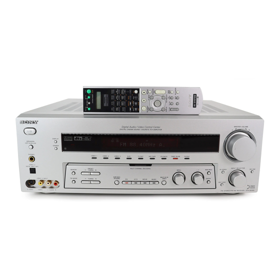
Photo: STR-DE895
SPECIFICATIONS
4)
or 100 W
4)
or 110 W
Canadian Model
Models of area code E2, E3, MX
Rated Power Output at Stereo Mode
(8 ohms 1 kHz, THD 0.7 %)
110 W + 110 W
2)
Reference Power Output
(8 ohms 1 kHz, THD 10 %)
1)
FRONT
:
130 W/ch
1)
CENTER
:
130 W
SURR
1)
:
130 W/ch
1)
3)
SURR BACK
:
130 W/ch
1) Depending on the sound field settings and the
source, there may be no sound output.
2) Measured under the following conditions:
Area code
Power requirements
E2, E3
240 V AC, 50 Hz
3) STR-DE995 only.
4) STR-DE895 only.
FM STEREO/FM-AM RECEIVER
US Model
STR-DE895/DE995
STR-DE995
E Model
STR-DE895
2)
4)
or 130 W
– Continued on next page –
1
Advertisement
Table of Contents

Related Manuals for Sony STR-DE895


Summary of Contents for Sony STR-DE895
- Page 1 (8 ohms 1 kHz, THD 0.7 %) FRONT 110 W/ch CENTER 110 W SURR 110 W/ch SURR BACK 110 W/ch or 110 W FM STEREO/FM-AM RECEIVER Sony Corporation 9-877-446-01 2003F04-1 Home Audio Company © 2003. 06 Published by Sony Engineering Corporation...
- Page 2 38.3 dBf, 22.5 µV/75 ohms and controls Usable sensitivity 11.2 dBf, 1 µV/75 ohms Mass (Approx.) 10.6 kg (23 lb 6 oz) (STR-DE995) 9.7 kg (21 lb 7 oz) (STR-DE895) Mono: 76 dB Stereo: 70 dB Supplied accessories Harmonic distortion at 1 kHz...
- Page 3 CRITIQUES POUR LA SÉCURITÉ DE FONCTIONNEMENT. NE REPLACE THESE COMPONENTS WITH SONY PARTS WHOSE REMPLACER CES COMPOSANTS QUE PAR DES PIÈCES SONY PART NUMBERS APPEAR AS SHOWN IN THIS MANUAL OR DONT LES NUMÉROS SONT DONNÉS DANS CE MANUEL OU IN SUPPLEMENTS PUBLISHED BY SONY.
-
Page 4: Table Of Contents
All manuals and user guides at all-guides.com STR-DE895/DE995 TABLE OF CONTENTS 1. GENERAL Main unit (STR-DE995 only) ..........5 Main unit (STR-DE895 only) ..........6 Remote button description (RM-PG412) ........ 7 Remote button description (RM-LG112) ........ 8 2. DISASSEMBLY 2-1. Case ..................9 2-2. -
Page 5: General
All manuals and user guides at all-guides.com STR-DE895/DE995 SECTION 1 GENERAL This section is extracted from instruction manual. -
Page 6: Main Unit (Str-De895 Only)
All manuals and user guides at all-guides.com STR-DE895/DE995... -
Page 7: Remote Button Description (Rm
All manuals and user guides at all-guides.com STR-DE895/DE995... -
Page 8: Remote Button Description (Rm-Lg112)
All manuals and user guides at all-guides.com STR-DE895/DE995... -
Page 9: Disassembly
All manuals and user guides at all-guides.com STR-DE895/DE995 SECTION 2 DISASSEMBLY Note : This set can be disassemble according to the following sequence. 2-1. CASE (Page 9) 2-2. FRONT PANEL SECTION 2-3. BACK PANEL (Page 10) (Page 10) 2-6. STANDBY BOARD 2-4. -
Page 10: Front Panel Section
All manuals and user guides at all-guides.com STR-DE895/DE995 2-2. FRONT PANEL SECTION 5 CNP210 4 CNP205 3 CNP508 6 two screws (BVTP3 x 8) 2 CNP701 1 CNS505 9 front panel section 7 five screws (BVTP3 x 8) 2-3. BACK PANEL... -
Page 11: Digital Board
All manuals and user guides at all-guides.com STR-DE895/DE995 2-4. DIGITAL BOARD 5 CNP508 0 DIGITAL board 2 CNP506 3 CNP510 4 CNP507 8 screw (BVTP3 x 8) 9 bracket (digital) 6 screw (BVTP3 x 8) 1 CNS505 2-5. MAIN BOARD... -
Page 12: Standby Board
All manuals and user guides at all-guides.com STR-DE895/DE995 2-6. STANDBY BOARD 4 three screws (BVTP3 x 6) 3 CNP905 5 STANDBY board 2 CNP813 1 CNP815... -
Page 13: Test Mode
All manuals and user guides at all-guides.com STR-DE895/DE995 SECTION 3 TEST MODE FACTORY PRESET MODE SOUND FIELD CLEAR MODE * All preset contents are reset to the default setting. * The preset sound field is cleared when this mode is activated. -
Page 14: Diagrams
All manuals and user guides at all-guides.com STR-DE895/DE995 SECTION 4 DIAGRAMS 4-1. IC PIN DESCRIPTIONS • IC1501 CXD9718Q (DSP) (DIGITAL Board (2/3)) Pin No. Pin Name Pin Description — Ground XRST Reset signal input from SYSTEM CONTROL IC EXTIN Not used (Connect to ground) - Page 15 All manuals and user guides at all-guides.com STR-DE895/DE995 Pin No. Pin Name Pin Description Boot stop signal input from SYSTEM CONTROL IC MOD1 Operation mode signal input (L: 386fs, H: 256fs) (Fixed at H) MOD0 Operation mode signal input (L: single chip mode, H: use prohibited) (Fixed at L)
- Page 16 All manuals and user guides at all-guides.com STR-DE895/DE995 • IC1101 MB91154PFV-G-113-BNDE1 (SYSTEM CONTROL) (DIGITAL Board (3/3)) Pin No. Pin Name Pin Description [7.1_DAT] MULTI CH IN DATA [7.1_CLK] MULTI CH IN CLOCK [006_LAT] TC9273_006 LATCH [011_LAT] TC9273_011 LATCH LED_DRV_DATA LED DATA...
- Page 17 All manuals and user guides at all-guides.com STR-DE895/DE995 Pin No. Pin Name Pin Description RSTX RESET IC — Power supply pin (+3.2 V) System clock signal input (16.5 MHz) System clock signal output (16.5 MHz) — Ground VOLT_DETECT_STOP VOLTAGE DOWN DETECT...
- Page 18 All manuals and user guides at all-guides.com STR-DE895/DE995 Pin No. Pin Name Pin Description SOTI FLASH PROGRAMMING SINI FLASH PROGRAMMING FL_CLK FL CLOCK FL_DIN/F1 FL DATA FL_LAT/F2 FL LATCH DRV.CLR/BLUE LED FL CLEAR BST SEL — Not used (Fixed at L) VOL_IC.DATA...
-
Page 19: Block Diagram - Tuner/Audio Section
All manuals and user guides at all-guides.com STR-DE895/DE995 4-2. BLOCK DIAGRAM — TUNER/AUDIO SECTION — RY300 RELAY DRIVER Q300 PRE AMP DE895 DE995 IC300 J305 (2/2) VIDEO 3 VIDEO 3 VIDEO 1 VIDEO 2 TV/SAT 3.3V INPUT INPUT MD/TAPE AUDIO... -
Page 20: Block Diagram - Digital Section
All manuals and user guides at all-guides.com STR-DE895/DE995 4-3. BLOCK DIAGRAM — DIGITAL SECTION — 6CH DAC CONVERTER IC1452 IC1401 IC1403 IC1402 IC1501 LOUT3- L OUT LOUT3+ SDTI3 SDTO AINL AUDIO L-IN DSI1 SD01 ROUT3- R-CH TUNER/ ROUT3+ SD02 24... -
Page 21: Block Diagram - Video Section
All manuals and user guides at all-guides.com STR-DE895/DE995 4-4. BLOCK DIAGRAM — VIDEO SECTION — COMPONENT VIDEO SELECTOR VIDEO AMP IC2308 IC2307 +5V-3 J2304 (1/2) 6dB AMP J2304 (2/2) XCOM VOUT2 VIN2 75Ω DRIVER 6dB AMP MONITOR COMPONENT ZCOM VIN3 VOUT3 75Ω... -
Page 22: Block Diagram - Key/Display Section
All manuals and user guides at all-guides.com STR-DE895/DE995 4-5. BLOCK DIAGRAM — KEY/DISPLAY SECTION — FL101 FLUORESCENT INDICATOR TUBE VIDEO SW1 36 V.SW1 SYSTEM VIDEO VIDEO SW2 37 V.SW2 CONTROL LED DRIVER SECTION IC1101 (3/4) VIDEO SW3 38 V.SW3 IC102... -
Page 23: Block Diagram - Osd Section
All manuals and user guides at all-guides.com STR-DE895/DE995 4-6. BLOCK DIAGRAM — OSD SECTION — CHARACTER GENERATOR Y/C SEPARATION IC2301 IC3100 V OUT V IN VIDEO AMP V CLAMP MON-V/IN Q2935 Q3100-3102 VIDEO VIDEO ANALOG Y OUT DYNAMIC Y IN... -
Page 24: Block Diagram - Power Section
All manuals and user guides at all-guides.com STR-DE895/DE995 4-7. BLOCK DIAGRAM — POWER SECTION — J2501 PHONES PRE DRIVER R-CH IC500 TM2880 +VOUT2 IN 2 DRIVE -VOUT2 FL-CH DRIVE POWER AMP RELAY Q571-574 DRIVER FR-CH R-CH CURRENT OVERLOAD Q240 FRONT B... -
Page 25: Circuit Boards Location
All manuals and user guides at all-guides.com STR-DE895/DE995 4-8. CIRCUIT BOARDS LOCATION THIS NOTE IS COMMON FOR PRINTED WIRING BOARDS AND SCHEMATIC DIAGRAMS. (In addition to this, the necessary note is printed in each block.) AC SELECT board (E2, E3 model) -
Page 26: Schematic Diagram - Main Section (1/3)
All manuals and user guides at all-guides.com STR-DE895/DE995 4-9. SCHEMATIC DIAGRAM — MAIN SECTION (1/3) — • Refer to page 25 for Common Note on Schematic Diagram and page 50 for IC Block Diagrams. (Page 38) (Page 36) CNP812 CNP814... -
Page 27: Schematic Diagram - Main Section (2/3)
All manuals and user guides at all-guides.com STR-DE895/DE995 4-10. SCHEMATIC DIAGRAM — MAIN SECTION (2/3) — • Refer to page 25 for Common Note on Schematic Diagram and page 50 for IC Block Diagrams. C423 C425 R427 CN851 R423 Q421... -
Page 28: Schematic Diagram - Main Section (3/3)
All manuals and user guides at all-guides.com STR-DE895/DE995 4-11. SCHEMATIC DIAGRAM — MAIN SECTION (3/3) — • Refer to page 25 for Common Note on Schematic Diagram. (Page 26) (Page 27) CN507 IC260 RY351 IC604 C261 C260 C395 R396 R398... -
Page 29: Printed Wiring Board - Main Section
All manuals and user guides at all-guides.com STR-DE895/DE995 4-12. PRINTED WIRING BOARD — MAIN SECTION — • Refer to page 25 for Circuit Boards Location and Common Note on Printed Wiring Boards, and page 30 for Semiconductor Location. TM602 TM601... -
Page 30: Printed Wiring Boards - Speaker B/Headphone Section
All manuals and user guides at all-guides.com STR-DE895/DE995 4-13. PRINTED WIRING BOARDS — SPEAKER B/HEADPHONE SECTION — • Refer to page 25 for Circuit Boards Location and Common Note on Printed Wiring Boards. • Semiconductor Location (MAIN Board) Ref. No. -
Page 31: Schematic Diagram - Speaker B/Headphone Section
All manuals and user guides at all-guides.com STR-DE895/DE995 4-14. SCHEMATIC DIAGRAM — SPEAKER B/HEADPHONE SECTION — • Refer to page 25 for Common Note on Schematic Diagram. RY2880 CNP851 TM2880 (Page 27) Q2881 D2880 R2870 CNP852 R2871 (Page 28) CNP701... -
Page 32: Printed Wiring Board - Digital Section (1/2)
All manuals and user guides at all-guides.com STR-DE895/DE995 4-15. PRINTED WIRING BOARD — DIGITAL SECTION (1/2) — • Refer to page 25 for Circuit Boards Location and Common Note on Printed Wiring Boards. • Semiconductor Location (Side A) Ref. No. -
Page 33: Printed Wiring Boards - Digital Section (2/2)
All manuals and user guides at all-guides.com STR-DE895/DE995 4-16. PRINTED WIRING BOARDS — DIGITAL SECTION (2/2) — • Refer to page 25 for Circuit Boards Location and Common Note on Printed Wiring Boards. (Page 29) (Page 39) TM301 (Page 48) -
Page 34: Schematic Diagram - Digital Section (1/3)
All manuals and user guides at all-guides.com STR-DE895/DE995 4-17. SCHEMATIC DIAGRAM — DIGITAL SECTION (1/3) — • Refer to page 25 for Waveforms and Common Note on Schematic Diagram and page 50 for IC Block Diagrams. CNP703 IC2710 C2703 L2702... -
Page 35: Schematic Diagram - Digital Section (2/3)
All manuals and user guides at all-guides.com STR-DE895/DE995 4-18. SCHEMATIC DIAGRAM — DIGITAL SECTION (2/3) — • Refer to page 25 for Waveforms and Common Note on Schematic Diagram and page 50 for IC Block Diagrams. (Page 34) FB1502 C1515... -
Page 36: Schematic Diagram - Digital Section (3/3)
All manuals and user guides at all-guides.com STR-DE895/DE995 4-19. SCHEMATIC DIAGRAM — DIGITAL SECTION (3/3) — • Refer to page 25 for Waveforms and Common Note on Schematic Diagram. (Page 34) JR1104 R1039 R1133 C1137 CNS505 IC1111 R1040 R1095 X1101... -
Page 37: Printed Wiring Boards - Audio Section
All manuals and user guides at all-guides.com STR-DE895/DE995 4-20. PRINTED WIRING BOARDS — AUDIO SECTION — • Refer to page 25 for Circuit Boards Location and Common Note on Printed Wiring Boards. J2001 J2552 J2553 J2551 C2001 C2002 TP200 CNP209... -
Page 38: Schematic Diagram - Audio Section
All manuals and user guides at all-guides.com STR-DE895/DE995 4-21. SCHEMATIC DIAGRAM — AUDIO SECTION — • Refer to page 25 for Common Note on Schematic Diagram and page 51 for IC Block Diagrams. J2551 R2551 C2552 C2553 J2552 E2561 CNP208... -
Page 39: Printed Wiring Board - S-Video Section
All manuals and user guides at all-guides.com STR-DE895/DE995 4-22. PRINTED WIRING BOARD — S-VIDEO SECTION — • Refer to page 25 for Circuit Boards Location and Common Note on Printed Wiring Boards. J2105 J2102 J2103 J2106 J2104 C2113 C2119 R2107... -
Page 40: Schematic Diagram - S-Video Section
All manuals and user guides at all-guides.com STR-DE895/DE995 4-23. SCHEMATIC DIAGRAM — S-VIDEO SECTION — • Refer to page 25 for Common Note on Schematic Diagram and page 51 for IC Block Diagrams. C2103 CNS204 C2102 J2102 IC B/D R2101... -
Page 41: Printed Wiring Board - Video Section (De895)
All manuals and user guides at all-guides.com STR-DE895/DE995 4-24. PRINTED WIRING BOARD — VIDEO SECTION (DE895) — • Refer to page 25 for Circuit Boards Location and Common Note on Printed Wiring Boards. J2304 J2301 J2302 J2303 J2305 C2376 R2316... -
Page 42: Printed Wiring Board - Video Section (De995)
All manuals and user guides at all-guides.com STR-DE895/DE995 4-25. PRINTED WIRING BOARD — VIDEO SECTION (DE995) — • Refer to page 25 for Circuit Boards Location and Common Note on Printed Wiring Boards. J2304 J2301 J2302 J2303 J2305 C2376 R2316... -
Page 43: Schematic Diagram - Video Section
All manuals and user guides at all-guides.com STR-DE895/DE995 4-26. SCHEMATIC DIAGRAM — VIDEO SECTION — • Refer to page 25 for Waveform and Common Note on Schematic Diagram, and page 51 for IC Block Diagrams. R2304 R2305 R2301 R2303 CNP253... -
Page 44: Printed Wiring Board - Up Convert Section (De995)
All manuals and user guides at all-guides.com STR-DE895/DE995 4-27. PRINTED WIRING BOARD — UP CONVERT SECTION (DE995) — • Refer to page 25 for Circuit Boards Location and Common Note on Printed Wiring Boards. R3132 R3133 L3103 C3133 Q3110 Q3108... -
Page 45: Schematic Diagram - Up Convert Section (De995)
All manuals and user guides at all-guides.com STR-DE895/DE995 4-28. SCHEMATIC DIAGRAM — UP CONVERT SECTION (DE995) — • Refer to page 25 for Waveform and Common Note on Schematic Diagram, and page 52 for IC Block Diagrams. IC B/D R3120... -
Page 46: Printed Wiring Boards - Display Section
All manuals and user guides at all-guides.com STR-DE895/DE995 4-29. PRINTED WIRING BOARDS — DISPLAY SECTION — • Refer to page 25 for Circuit Boards Location and Common Note on Printed Wiring Boards. S152 S103 S134 JW130 R122 S114 S113 S112... -
Page 47: Schematic Diagram - Display Section
All manuals and user guides at all-guides.com STR-DE895/DE995 4-30. SCHEMATIC DIAGRAM — DISPLAY SECTION — • Refer to page 25 for Common Note on Schematic Diagram. R198 R199 RV101 FL101 CNS102 CNP102 RV102 IC103 R106 JW101 JW102 D103 JW103 IC100... -
Page 48: Printed Wiring Boards - Power Section
All manuals and user guides at all-guides.com STR-DE895/DE995 4-31. PRINTED WIRING BOARDS — POWER SECTION — • Refer to page 25 for Circuit Boards Location and Common Note on Printed Wiring Boards. J911 S901 R901 CNP901 CNP905 F901 JW954 CNP902... -
Page 49: Schematic Diagram - Power Section
All manuals and user guides at all-guides.com STR-DE895/DE995 4-32. SCHEMATIC DIAGRAM — POWER SECTION — • Refer to page 25 for Common Note on Schematic Diagram. T901 (Page 28) (Page 28) CNP815 ETP902 C902 R861 R862 D865 CNP813 Q911 R913... -
Page 50: Ic Block Diagrams
All manuals and user guides at all-guides.com STR-DE895/DE995 4-33. IC BLOCK DIAGRAMS IC402 TC9273N-011 IC1301 LC89056W-E 12 11 10 9 8 7 6 5.1L 5.1R XMODE CKSEL1 6.1L 6.1R CKSEL0 DOSEL1 LOUT ROUT 44 DOSEL0 CKOUT DVDD 5.1SL 5.1SR DGND... - Page 51 All manuals and user guides at all-guides.com STR-DE895/DE995 IC1451 AK4381VT-E2 IC2560 TC9273N-006 IC2103 NJM2145D (STR-DE995 only) 16 DZFL OUT1 INH1 15 DZFR 14 VDD INH2 MCLK INPUT VIDEO1 R VIDEO1 L 13 VSS CIRCUIT VIDEO2 R VIDEO2 L 12 AOUTL+ ∆Σ...
- Page 52 All manuals and user guides at all-guides.com STR-DE895/DE995 IC2301 MB90089PF-G-238-BND (STR-DE995 only) IC2308 TC74HC4053AP IC3101 MM1093NF (STR-DE995 only) CHROMA AVSS COMPOSITE 15 14 YOUT ANALOG COUT SYNC SWITCH VOUT BURST GATE AVCC FILTER FILTER FSCO SERIAL VIDEO INPUT 4FSC SIGNAL...
-
Page 53: Exploded Views
All manuals and user guides at all-guides.com STR-DE895/DE995 SECTION 5 EXPLODED VIEWS NOTE: • The mechanical parts with no reference • -XX and -X mean standardized parts, so The components identified by mark 0 or dotted line with mark number in the exploded views are not supplied. -
Page 54: Front Panel Section
All manuals and user guides at all-guides.com STR-DE895/DE995 5-2. FRONT PANEL SECTION FL101 not supplied (2ND ROOM board) supplied with RV101 supplied with RV102 Ref. No. Part No. Description Remark Ref. No. Part No. Description Remark X-4955-310-1 FRONT PANEL ASSY (BLACK)...(BLACK) 4-244-235-01 KNOB (MENU) (BLACK)...(BLACK) -
Page 55: Chassis Section-1
All manuals and user guides at all-guides.com STR-DE895/DE995 5-3. CHASSIS SECTION-1 F904 #1 #1 #1 #1 not supplied TM301 not supplied The components identified by Les composants identifiés par une mark 0 or dotted line with mark marque 0 sont critiques pour 0 are critical for safety. -
Page 56: Chassis Section-2
All manuals and user guides at all-guides.com STR-DE895/DE995 5-4. CHASSIS SECTION-2 not supplied (GUIDE board) not supplied F902 F901 (BLOCK board) Q624 Q723 Q724 Q523 Q674 Q673 Q423 Q474 Q473 Q623 Q524 not supplied Q574 Q573 Q424 T901 not supplied... -
Page 57: Electrical Parts List
All manuals and user guides at all-guides.com STR-DE895/DE995 SECTION 6 AC SEL AUDIO VIDEO ELECTRICAL PARTS LIST DIGITAL NOTE: • Due to standardization, replacements in • SEMICONDUCTORS The components identified by mark 0 or dotted line with mark the parts list may be different from the In each case, u : µ, for example:... - Page 58 All manuals and user guides at all-guides.com STR-DE895/DE995 DIGITAL Ref. No. Part No. Description Remark Ref. No. Part No. Description Remark C1101 1-164-156-11 CERAMIC CHIP 0.1uF C1351 1-164-156-11 CERAMIC CHIP 0.1uF C1102 1-164-156-11 CERAMIC CHIP 0.1uF C1352 1-164-156-11 CERAMIC CHIP 0.1uF...
- Page 59 All manuals and user guides at all-guides.com STR-DE895/DE995 DIGITAL Ref. No. Part No. Description Remark Ref. No. Part No. Description Remark C1483 1-164-315-11 CERAMIC CHIP 470PF D1109 8-719-016-74 DIODE 1SS352 C1488 1-126-964-11 ELECT 10uF D1110 8-719-016-74 DIODE 1SS352 (DE995) D1111...
- Page 60 All manuals and user guides at all-guides.com STR-DE895/DE995 DIGITAL Ref. No. Part No. Description Remark Ref. No. Part No. Description Remark < JACK > R1087 1-216-833-11 METAL CHIP 1/10W (DE895) J1301 1-794-972-11 JACK, PIN 1P (DIGITAL (ASSIGNABLE) R1088 1-216-833-11 METAL CHIP...
- Page 61 All manuals and user guides at all-guides.com STR-DE895/DE995 DIGITAL Ref. No. Part No. Description Remark Ref. No. Part No. Description Remark R1148 1-216-797-11 METAL CHIP 1/10W R1199 1-216-841-11 METAL CHIP 1/10W R1149 1-216-809-11 METAL CHIP 1/10W (DE995) R1150 1-216-809-11 METAL CHIP...
- Page 62 All manuals and user guides at all-guides.com STR-DE895/DE995 DIGITAL Ref. No. Part No. Description Remark Ref. No. Part No. Description Remark R1422 1-216-829-11 METAL CHIP 4.7K 1/10W R1508 1-216-809-11 METAL CHIP 1/10W R1423 1-216-812-11 METAL CHIP 1/10W R1509 1-216-809-11 METAL CHIP...
- Page 63 All manuals and user guides at all-guides.com STR-DE895/DE995 DISPLAY Ref. No. Part No. Description Remark Ref. No. Part No. Description Remark A-4731-941-A DISPLAY BOARD, COMPLETE (DE995) < COIL > A-4731-969-A DISPLAY BOARD, COMPLETE (DE895:US) A-4731-980-A DISPLAY BOARD, COMPLETE (E2,E3) L101...
- Page 64 All manuals and user guides at all-guides.com STR-DE895/DE995 DISPLAY FRONT AV HEADPHONE MAIN Ref. No. Part No. Description Remark Ref. No. Part No. Description Remark S111 1-771-410-21 SWITCH, TACTILE (MUSIC) 1-687-149-11 JOG BOARD S112 1-771-410-21 SWITCH, TACTILE (MOVIE) ********** S113 1-771-410-21 SWITCH, TACTILE (A.F.D.)
- Page 65 All manuals and user guides at all-guides.com STR-DE895/DE995 MAIN Ref. No. Part No. Description Remark Ref. No. Part No. Description Remark C342 1-128-825-11 CERAMIC 0.0022uF 5% C459 1-124-257-00 ELECT 2.2uF C343 1-128-825-11 CERAMIC 0.0022uF 5% C460 1-126-961-11 ELECT 2.2uF C344 1-128-825-11 CERAMIC 0.0022uF 5%...
- Page 66 All manuals and user guides at all-guides.com STR-DE895/DE995 MAIN Ref. No. Part No. Description Remark Ref. No. Part No. Description Remark C582 1-136-161-00 FILM 0.047uF C716 1-126-934-11 ELECT 220uF C590 1-126-963-11 ELECT 4.7uF (DE995) C593 1-127-880-11 CERAMIC 0.022uF C721 1-126-947-11 ELECT...
- Page 67 All manuals and user guides at all-guides.com STR-DE895/DE995 MAIN Ref. No. Part No. Description Remark Ref. No. Part No. Description Remark D575 8-719-991-33 DIODE 1SS133T-77 Q220 8-729-021-82 TRANSISTOR 2SD2396K D576 8-719-991-33 DIODE 1SS133T-77 Q225 8-729-140-84 TRANSISTOR 2SC1841-PAFAEA D600 8-719-991-33 DIODE 1SS133T-77...
- Page 68 All manuals and user guides at all-guides.com STR-DE895/DE995 MAIN Ref. No. Part No. Description Remark Ref. No. Part No. Description Remark < RESISTOR > R354 1-249-408-11 CARBON 1/4W R355 1-249-428-11 CARBON 8.2K 1/4W R200 1-249-437-11 CARBON 1/4W R356 1-249-441-11 CARBON...
- Page 69 All manuals and user guides at all-guides.com STR-DE895/DE995 MAIN Ref. No. Part No. Description Remark Ref. No. Part No. Description Remark R439 1-249-389-11 CARBON 1/4W F R535 1-249-437-11 CARBON 1/4W R440 1-249-437-11 CARBON 1/4W R536 1-249-433-11 CARBON 1/4W R441 1-249-437-11 CARBON...
- Page 70 All manuals and user guides at all-guides.com STR-DE895/DE995 MAIN Ref. No. Part No. Description Remark Ref. No. Part No. Description Remark R636 1-249-433-11 CARBON 1/4W R725 1-249-405-11 CARBON 1/4W F R637 1-249-437-11 CARBON 1/4W (DE995) R639 1-249-389-11 CARBON 1/4W F...
- Page 71 All manuals and user guides at all-guides.com STR-DE895/DE995 OPTICAL3 POWER S-VIDEO Ref. No. Part No. Description Remark Ref. No. Part No. Description Remark 1-687-146-11 OPTICAL3 BOARD C2115 1-128-805-11 CERAMIC 47PF C2116 1-128-805-11 CERAMIC 47PF *************** C2117 1-126-964-11 ELECT 10uF < CAPACITOR >...
- Page 72 All manuals and user guides at all-guides.com STR-DE895/DE995 S-VIDEO SPEAKER B STANDBY Ref. No. Part No. Description Remark Ref. No. Part No. Description Remark R2115 1-249-429-11 CARBON 1/4W < CONNECTOR > (DE995) R2116 1-249-429-11 CARBON 1/4W CNP813 1-784-926-11 PIN, CONNECTOR 11P...
- Page 73 All manuals and user guides at all-guides.com STR-DE895/DE995 UP CONVERT Ref. No. Part No. Description Remark Ref. No. Part No. Description Remark A-4731-956-A UP CONVERT BOARD, COMPLETE (DE995) C3130 1-126-963-11 ELECT 4.7uF (DE995) *************************** C3131 1-162-974-11 CERAMIC CHIP 0.01uF < CAPACITOR >...
- Page 74 All manuals and user guides at all-guides.com STR-DE895/DE995 UP CONVERT VIDEO Ref. No. Part No. Description Remark Ref. No. Part No. Description Remark < RESISTOR > R3133 1-216-818-11 METAL CHIP 1/10W (DE995) R3101 1-216-822-11 METAL CHIP 1.2K 1/10W R3134 1-260-354-71 CARBON...
- Page 75 All manuals and user guides at all-guides.com STR-DE895/DE995 VIDEO Ref. No. Part No. Description Remark Ref. No. Part No. Description Remark C2313 1-162-919-11 CERAMIC CHIP 22PF C2371 1-126-964-11 ELECT 10uF (DE995) (DE995) C2314 1-162-913-11 CERAMIC CHIP 0.5PF C2372 1-126-964-11 ELECT...
- Page 76 All manuals and user guides at all-guides.com STR-DE895/DE995 VIDEO VIDEO3 2ND ROOM Ref. No. Part No. Description Remark Ref. No. Part No. Description Remark < RESISTOR > R2336 1-218-285-11 METAL CHIP 1/10W R2337 1-216-821-11 METAL CHIP 1/10W R2301 1-216-821-11 METAL CHIP...
- Page 77 All manuals and user guides at all-guides.com STR-DE895/DE995 Ref. No. Part No. Description Remark Ref. No. Part No. Description Remark MISCELLANEOUS ACCESSORIES *************** ************ 1-773-291-11 WIRE (FLAT TYPE) (29 CORE) 1-477-794-11 COMMANDER, STANDARD (RM-PG412) 1-773-106-11 WIRE (FLAT TYPE) (19 CORE)
- Page 78 All manuals and user guides at all-guides.com STR-DE895/DE995 REVISION HISTORY Clicking the version allows you to jump to the revised page. Also, clicking the version at the upper on the revised page allows you to jump to the next revised page.