Advertisement
Quick Links
Advertisement

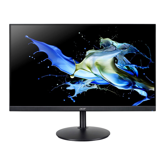
Summary of Contents for Acer CB242Y
- Page 1 Acer Monitor CB242Y LIFECYCLE EXTENSION GUIDE...
-
Page 2: Table Of Contents
Contents Table of Contents Important Safety Notice ................. 3 1. Exploded Diagram ..................4 2. Wiring connectivity diagram ..............5 3. Mechanical Instruction ................6 4. Disassembly and Assembly SOP ............7 5. Troubleshooting ..................13 6. FRU List ..................... 15 Safety Notice Any person attempting to service this chassis must familiarize with the chassis and be aware of the necessary safety precautions to be used when serving electronic equipment containing... -
Page 3: Important Safety Notice
ACER CB242Y Important Safety Notice Product Announcement: This product is certificated to meet RoHS Directive and Lead-Free produced definition. Using approved critical components only is recommended when the situation to replace defective parts. Vender assumes no liability express or implied, arising out of any unauthorized modification of design or replacing non-RoHS parts. -
Page 4: Exploded Diagram
ACER CB242Y 1. Exploded Diagram 1.1 Product Exploded Diagram Item ODM DESCRIPTION Item ODM DESCRIPTION ASSY BZL FFC LVDS PCBA LED BD ASSY SHD Lamp wire WIRE LCDM SCRW MID-FRAME ASSY RC SCRW PCBA CTRL ASSY CLMN SCRW ASSY BASE... -
Page 5: Wiring Connectivity Diagram
ACER CB242Y 2. Wiring connectivity diagram There are two types of wiring diagrams for model CB242Y. The wiring connectivity position will be different according to the ACTUAL PCBA connector position. Please base on different SKU refer to below diagram. NOTE: INF BD= Interface Board, PWR BD=Power Board, CTRL BD= Control Board 1. -
Page 6: Mechanical Instruction
ACER CB242Y 3. Mechanical Instruction Tools Required List the type and size of the tools that would typically can be used to disassemble the product to a point where components and materials requiring selective treatment can be removed. Tool Description:... -
Page 7: Disassembly And Assembly Sop
ACER CB242Y 4. Disassembly and Assembly SOP CB242Y 4.1 Disassembly Procedures Preparation before disassemble 1.Clean the room for disassemble 2.Identify the area for monitor 3.Check the position that the monitors be placed and the quantity of the monitor ;prepare the area for material flow;... - Page 8 ACER CB242Y Tear off four BOPP tapes on the speaker wire. Extract the connect of the speaker from the PCBA. Disassemble the speaker from the MF(Middle Frame). Disassemble the speaker from the MF Extract the FFC LED from the I/F BD and tear it off from SHD as picture 1.
- Page 9 ACER CB242Y Extract FFC wire from the panel as picture 1. Unlock 9 screws from the MF as picture 2. Disassemble the MF from Disassemble the MF from the panel. Extract the lamp wire from the panel as the picture 3.
- Page 10 ACER CB242Y 4.2 Assembly Procedures Preparation before disassemble 1.Clean the room for disassemble 2.Identify the area for monitor 3.Check the position that the monitors be placed and the quantity of the monitor ;prepare the area for material flow; according to the actual condition plan the disassemble layout 4.Prepare the implement, equipment, materials as bellow:...
- Page 11 ACER CB242Y Assemble FFC LED to the PCBA LED BD as the picture 1. Assemble the PCBA LED BD into the ASSY TRIM. Assemble the ASSY TRIM Assemble the ASSY TRIM on the MF. Lock two MD screws to the ASSY TRIM.
- Page 12 ACER CB242Y Insert the speaker connect to the I/F BD as the picture. Arrange the SPK wire on the Panel and stick 4 pieces of black tapes to fasten the SPK Assemble the speaker on wire as picture. the MF (Attention: Keep the speaker wire straight, and the middle of the speaker wire is not allowed to be placed on the step of the panel.)
-
Page 13: Troubleshooting
ACER CB242Y 5. Troubleshooting TROUBLESHOOTING Before sending your LCD monitor for servicing, please check the trouble-shooting list below to see if you can self-diagnose the problem. (VGA Mode) Problems Current Status Remedy Using OSD, adjust brightness and contrast to ... - Page 14 ACER CB242Y (HDMI/DP Mode) Problems Current Status Remedy Using OSD, adjust brightness and contrast to LED ON maximum or reset to their default settings. Check the power switch. LED OFF Check if AC power cord is properly connected ...
-
Page 15: Fru List
6. FRU List This chapter gives you the FRU (Field Replaceable Unit) listing in global configurations of ACER CB242Y. Refer to this chapter whenever ordering for parts to repair or for RMA (Return Merchandise Authorization). Please note that WHEN ORDERING FRU PARTS, you should c heck the most up-to-date information available on your regional web or channel.


