Advertisement
Quick Links
P P G G 2 2 0 0 - 4 4 0 0 S S e e r r i i e e s s
P P G G 1 1 0 0 0 0 0 0 - 1 1 5 5 0 0 0 0 S S e e r r i i e e s s
CAUTION:
T
URN OFF POWER TO THE ELECTRIC SERVICE OR PANEL AND TO EQUIPMENT TO BE PROTECTED BEFORE
INSTALLING ANY
CIAN AND SHOULD COMPLY WITH THE
INSTALLATION:
1. Test and verify system voltage to assure proper
model selection of Surge Protection Device (SPD).
Refer to the wiring diagrams, configurations and volt-
ages on page 2 for additional information.
2. Turn Power OFF.
3. Select a position in the load center or equipment
panel that will require the shortest length of wire lead
for connection. If installing on a breaker panel, the dis-
tance from the main breaker or input lugs to the con-
necting breaker is not as important as maintaining
short wire lead lengths.
4. Determine the path of the lead wires making sure
to avoid sharp 90 degree bends. Attempt to use 2" or
larger bends.
5. Remove the
equipment panel that best suits positioning of the SPD
for optimum location.
6. Mount the SPD to the panel or an adjacent wall. If
the mounting position prevents the direct connection of
the nipple to the load center or equipment panel, a
short piece of conduit or flexible conduit such as "sealtite" must be used to comply with the National
Electrical Code and local codes.
7. Twist or ty-wrap lead wires to eliminate any space or gaps between them. Pass the wires
through the selected knockout and secure the SPD.
8. Cut each wire lead to the proper length. DO NOT coil extra wire length.
INSTALLATION INSTRUCTIONS and OPERATIONS MANUAL
HARDWIRED SURGE PROTECTION DEVICES
S
P
URGE
ROTECTION
Suitable For Use on a Circuit Capable of Delivering Not More
Than 200,000 rms symmetrical Amperes.
DO NOT OPEN - contains no serviceable parts
knockout from the load center or
INSTALLATION INSTRUCTIONS
OPERATIONS MANUAL
D
. A
EVICE
LL WIRING SHOULD BE DONE BY A QUALIFIED ELECTRI
N
E
C
ATIONAL
LECTRIC
and
ODE AND LOCAL ELECTRIC CODES
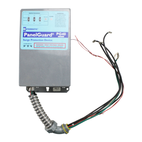
Model PG40-480-3D
Other models and voltage configurations
will appear slightly different
PG20-40 SERIES - V.11-03
-
.
Advertisement

Related Manuals for Intermatic PG1000 Series


Summary of Contents for Intermatic PG1000 Series
- Page 1 P P G G 2 2 0 0 - 4 4 0 0 S S e e r r i i e e s s P P G G 1 1 0 0 0 0 0 0 - 1 1 5 5 0 0 0 0 S S e e r r i i e e s s HARDWIRED SURGE PROTECTION DEVICES CAUTION: URN OFF POWER TO THE ELECTRIC SERVICE OR PANEL AND TO EQUIPMENT TO BE PROTECTED BEFORE...
- Page 2 16. Make sure that each indicator on the SPD is ON. If not, turn power off and recheck each instal- lation step listed above. 17. For troubleshooting assistance, call Intermatic at 815-675-7000 and ask for Technical Support. INSTALLATION INSTRUCTIONS and OPERATIONS MANUAL...
- Page 3 2. Confirm that proper voltage is present at all device input leads and all leads are securely fastened. Voltage per mode 3. If alarm condition can not be corrected, contact Intermatic at 815-675-7000 and select Technical Support. ALARM SWITCH OPERATION Normal Position: required for proper operation.
- Page 4 (2) What Is Not Covered By This Warranty Intermatic does not warrant (a) defects in the Product or damage to any equipment caused by the failure to properly install the Product, (b) damage caused by use of the Product for purposes other than those for which it was designed, (c) damage caused by disaster...