Table of Contents
Advertisement
Quick Links
Advertisement
Table of Contents

Related Manuals for Nambuk NRD-1000

Summary of Contents for Nambuk NRD-1000
- Page 1 Product Manual NRD - 1000 Radial Drilling Machine 1 . Product manual must be read before use. 2 . Please read all instructions carefully prior to operate the machine. 3 . This machine is produced by Korea Certification Safety(KCS) And Product Liability(PL)
-
Page 2: Table Of Contents
Operating Manual NRD-1000 Table of Contents Introduction Important Safeguards 2-1 Warning Sign 2-2 Warning Symbols 2-3 Warning Label 2-4 Attachment of Warning Label 2-5 Safety Precaution Product Description 3-1 Specifications 3-2 Descriptions of each part of the machine 3-3 Accessories... - Page 3 10-2 Protection Guard Manufacturing Diagram Cutting Data ● Notice We are truly grateful for purchasing our Radial Drilling Machine “NRD-1000”. NRD-1000 is easy to operate and was designed in accordance with KSB-4036 for safety and raising productivity. This manual will provide you information and safety use of NRD-1000 Please contact us for more information and details with the type of the machine and serial number.
-
Page 4: Introduction
NRD-1000 1. Introduction Please read all instructions carefully prior to operate the NRD-1000 w This operating manual for the Radial M/C is for person who install, repair and run the machine. w It explains basic details applicable all machine. Also, this manual is easy to understand for beginners as well as consumers who use the machine for the first time. -
Page 5: Important Safeguards
Operating Manual NRD-1000 ◉Warning Labels are attached to the Radial Machine for safety. the meanings of key words used in this manual to indicate the extent of danger to persons or to the machine are defined below. These are based on the American National Standards Institute(ANSI). -
Page 6: Warning Symbols
Operating Manual NRD-1000 2-2. Warning Symbols ▮Warning symbols are on the manual and the machine, they require attention. Electric shock Keep away Injuries by the spindle Do not disassemble Scattering No Gloves Caught in the spindle Fully aware of manual... - Page 7 Operating Manual NRD-1000 2-3. Warning Labels wElectric Shock Please be aware of high voltage flowing in the electric box Electric shock could cause death or serious injuries. Please turn off power before servicing wInjuries by spindle or tools Do not touch with hand in gloved, it could get caught in the spindle during...
-
Page 8: Warning Label
Operating Manual NRD-1000 2-4. Attachment of warning label WARNING w Warning label should be kept clean and never removed Not well-informed of risk could cause serious injuries or malfunction ☞ One or more warning labels are attached on this machine. - Page 9 Operating Manual NRD-1000 ▮Label number : PL-03 ▮Label number : PL-04 WARNING PL-03 Entanglement Ground connection required. Do not Turn off power No wet hands ground onto when repair when switching. inappropriate place like gas pipes. ▮Label location 경고 WARNING PL-03 고전압...
-
Page 10: Safety Precaution
Operating Manual NRD-1000 2-5. Safety Precautions DANGER wTurn off main power when opening the electric box. w Do not switch when hands are wet. WARNING wDo not touch chips or spindle when operating(Do not touch with bare hand even when stopped since the blades of the tool are sharp) Do not remove the safety cover during operating, it could cause your hands or fingers get caught in the belt. - Page 11 Operating Manual NRD-1000 WARNING wChips in the machine should be removed by a hook with safety glasses on after the spindle is stopped completely. wObjects you work on should be fixed firmly or they could pop up wGround connection is required. Do not ground onto inappropriate place like gas pipes.
- Page 12 Operating Manual NRD-1000 WARNING wAfter using the machine, it requires cleaning and fueling. Wipe the rusty parts with cutting oil. wRegular repair and check required. wOnly skilled workers operate the machine. A person who is not well-informed about the machine could cause serious risks.
-
Page 13: Product Description
Operating Manual NRD-1000 3. Product Description Specifications Specifications Unit NRD-1000 Steel Drilling capacity Cast iron Capacity Steel Tapping capacity Cast iron Diameter of column Distance center of spindle 1000 to face of column Distance center of 1285 column to end of arm... -
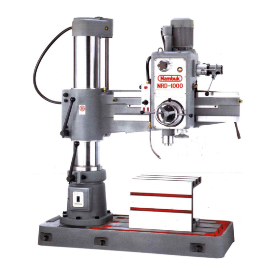
Page 14: Descriptions Of Each Part Of The Machine
Operating Manual NRD-1000 3-2 Descriptions of each part of the machine 0.22 15 16 Base Switch box Work table Spindle Column Handle for fine-feed No fuse braker S/W Rack for spindle box traverse Column sleeve Handle for spindle box traverse... -
Page 15: Characteristics Of Product
Operating Manual NRD-1000 3-3 Accessories Working table 410× 530× 400 Coolant system 1 set Anchor bolts 5/8"× 400ℓ 1 set Leveling plates & bolts 1 set Tool box 1 ea Allen wrench 2.5~14mm(10 kinds) 1 set Double spanner 8 X 9 ~ 30× 32(6 kinds) -
Page 16: Feed Gear
Operating Manual NRD-1000 4-3. Spindle driving gear 4-8. Column & Sleeve Every kind of gear and shaft is made by Column is vertically assembled on Base by fitting carburizing heat-treatment with Column Sleeve outside, which allows Arm to elevate chrome-molybdenum steel and the ground, through flesh side. -
Page 17: Transportation And Installation Of Machine
Operating Manual NRD-1000 5. Transportation and Installation of Machine 5-1. Transportation and Unload Machine ◆Machine Unloading Method During movement, transportation and unloading of this machine, please put down the arm to the lowest position ⓑ, the working level, the spindle box at table at position ⓐ, adjust... -
Page 18: Wiring
Operating Manual NRD-1000 5-2. Wiring Power Source Terminal Connect Electric Power source, R.S.T terminals. After power on, press “NO”switch in no fuse braker front of machine, and Pilot Lamp will be lighted up. In case of not being lighted up, two lines among three lines of power source should be exchanged. -
Page 19: Balance Of Product
Operating Manual NRD-1000 5-4. Balance of Product Balance of the machine is very important to leveling bolt maintain processing precision durability. When the machine is initially installed, if it foundation bolt is hard to maintain balance due to long period... - Page 20 Operating Manual NRD-1000 Oiling List Mark Places to be oil Oil volume Oil Time Oil Recommended First months, Spindle Box Approx. 2ℓ MOBILL D.T.E OIL LIGHT Exchange every 6 Spindle Box Refueling Oil cup months ever since Grease nipple of lower edge of spindle...
-
Page 21: Operation Of The Machine
Operating Manual NRD-1000 6. Operation of the machine 6-1. Power Source Input of the Machine 6-2. Rotation Direction of Spindle Life Braker switch at front lower part of After fixing rotation times into the lowest, column and then press “ON”switch of operation... -
Page 22: Column & Arm Clamp
Operating Manual NRD-1000 6-5. Column & Arm Clamp 6-7. Selection of Spindle Rotation In moving column and Arm clamp lever right of Spindle Rotation is 9 stage of speed change point middle, and It is stay in clamp and than 48~1525rpm by spindle change lever. -
Page 23: Manual Feed Of Spindle
Operating Manual NRD-1000 6-10. Manual Feed of Spindle 6-12. Selection of the depth of Automatic Manual feed of the spindle is carried out by Feed of Spindle manually turning spindle feed On the dial of Spindle Feed, 0~110 notch is... -
Page 24: Adjustment Of Machine
Operating Manual NRD-1000 7. Adjustment of Machine 7-3 Adjustment of Spindle Box Clamp 7-1. Adjustment of Column Clamp After using for a longtime, when clamp lever lock, If right and left move of spindle box, If the column has a low clamping force(if the... -
Page 25: Adjustment Of Safety Clutch For Spindle Feed
Operating Manual NRD-1000 ⦁Adjustment Before and behind leveling same left right horizontal leveling, clamp condition of spindle box is Adjust nut release before behind horizontal leveling bolt(2EA) is complete tight, The next, as before and behind moving of spindle box is smoothness, standardize release to before and behind adjust bolt. -
Page 26: Electric Wiring
Operating Manual NRD-1000 8. Electric Wiring After opening braker cover at lower part of column and connecting power lines to terminals at upper part of braker, lift braker at the position of “ON”. And pilot lamp is light up. This time, operate to monolever switch so certificate same a direction, spin indication of cover and spindle spin indication. -
Page 27: List And Usage Of Electrical Component
Operating Manual NRD-1000 8-1 List and Usage of Electrical Components Symbol Product Names Spec, Manufacturer Usage Motor 2.2kw-4P HIGEN Spindle Motor Motor 0.75kw-4P " Arm Elevating Motor Motor 0.1kw-2P " Coolant Motor Auto breaker ABS33.3P.20A LS IS MAIN power Magnetic contactor... -
Page 28: Electric Circuit Diagram
Operating Manual NRD-1000 8-2 Electric Circuit Diagram 1 MODEL 기 기 TITLE 주회로 NRD-1000 종 종 품 도 전기회로도 10E0001 1/2 번 명 일 2013. 03. 06 주식회사 남 북 기호 변경일자 변 경 사 항 담 당 자 Nambuk Co.,Ltd... - Page 29 Operating Manual NRD-1000 8-2 Electric Circuit Diagram 2 WORKING LIGHT PB 1 PB 2 POWER ON PILOT LAMP MONOLEVER S/W SPINDLE FORWARD SPINDLE REVERSE TIMER ARM UP ARM DOWN COOLANT PUMP MODEL 기 기 TITLE 보조회로 NRD-1000 종 종 품...
- Page 30 Operating Manual NRD-1000 8-2 Electric Circuit Diagram 3 AWG18(0.75SQ) 중판 (제어반) AWG18(0.75SQ) KIV1.5SQ S/W BOX KIV1.5SQ KIV2.5SQ KIV1.5SQ COVER KIV1.5SQ COVER KIV2.5SQ SPINDLE MOTOR KIV1.5SQ MOTOR KIV0.75SQ COOLANT MOTOR MODEL 기 기 TITLE 접 지 도 NRD-1000 종 종 품...
- Page 31 Operating Manual NRD-1000 8-2 Electric Circuit Diagram 4 Nambuk Co.,Ltd...
-
Page 32: Switch Explanation Of Electric Circuit Diagram
Operating Manual NRD-1000 8-3 Switch Explanation of Electric Circuit Diagram Symbols Names Explanations Remarks ① PBL1 Pilot button switch Lights up when normal power is set to ON. Green power pressed ② Emergency Stop Switch emergency. If operating toward the corresponding direction, ③... -
Page 33: Parts List
Operating Manual NRD-1000 9. PARTS LIST Nambuk Co.,Ltd... - Page 34 Operating Manual NRD-1000 9. PARTS LIST Product Names Qty. Prd No. Remarks Product Names Qty. Prd No. Remarks Base 10C001 Ball bearing 6020 Working table 10C002 Thrust ball bearing 51118 Anchor bolt M16×400ℓ Roller 13C019 Plain washer Column sleeve 10C010...
- Page 35 Operating Manual NRD-1000 9. PARTS LIST Nambuk Co.,Ltd...
- Page 36 Operating Manual NRD-1000 9. PARTS LIST Product Names Qty. Prd No. Remarks Product Names Qty. Prd No. Remarks Grip ∅40 119 Clamp bolt 10A009 Lever 10A015 120 Nut 10A016 Lever boss 10A014 121 Cam 10A017 Taper pin ∅6×50ℓ 122 Setscrew with hex.socket M5×6ℓ...
- Page 37 Operating Manual NRD-1000 9. PARTS LIST Nambuk Co.,Ltd...
- Page 38 Operating Manual NRD-1000 9. PARTS LIST Product Names Qty. Prd NO. Remarks Product Names Qty. Prd No. Remarks 144 Lock nut AN05 164 Ball cap ∅10 145 Lock washer AW05 165 Screw bush 10A003 146 Worm wheel 10A034 166 Subsidiary bush...
- Page 39 Operating Manual NRD-1000 9. PARTS LIST Nambuk Co.,Ltd...
- Page 40 Operating Manual NRD-1000 9. PARTS LIST Product Names Qty. Prd No. Remarks Product Names Qty. Prd No. Remarks 184 Hex.socket head bolt ×16ℓ 217 Collar 10S012 185 Spring washer 218 22T Gear 10S014 186 Cap 10S009 219 Key 7×7×29ℓ 187 20T Gear...
- Page 41 Operating Manual NRD-1000 9. PARTS LIST Nambuk Co.,Ltd...
- Page 42 Operating Manual NRD-1000 9. PARTS LIST Product Names Qty. Prd No. Remarks Product Names Qty. Prd No. Remarks 249 Hex.socket head bolt ×12ℓ 269 Pusher 10S055 250 Lifter 10S050 270 Spring 10S056-1 251 Bracket 10S049 271 Steel ball ∅6 252 Setscrew with hex.socket ×6ℓ...
- Page 43 Operating Manual NRD-1000 9. PARTS LIST Nambuk Co.,Ltd...
- Page 44 Operating Manual NRD-1000 9. PARTS LIST Product Names Qty. Prd No. Remarks Product Names Qty. Prd No. Remarks 289 Handle 10S117 326 Rack shaft 10S097 290 Setscrew with hex.socket ×5ℓ 327 Bush 10S098 291 Spring pin ×35ℓ 328 Gear 10S102 ∅4...
- Page 45 Operating Manual NRD-1000 9. PARTS LIST Nambuk Co.,Ltd...
- Page 46 Operating Manual NRD-1000 9. PARTS LIST Product Names Qty. Prd No. Remarks Product Names Qty. Prd No. Remarks 363 Handle 10S085 391 Dia Disk 10S073 364 Spring pin ×36ℓ 392 Hex.socket head bolt M6×12ℓ ∅4 365 Lock nut 393 Clutch...
- Page 47 Operating Manual NRD-1000 9. PARTS LIST Product Names Qty. Prd No. Remarks Product Names Qty. Prd No. Remarks 418 Name plate 10N001 428 Connector VFC-108 419 Cross-recessed head screw ×6ℓ 429 Flexible tube VF-8 420 Rocker S/W 430 Connector VFC-308...
- Page 48 Operating Manual NRD-1000 9. PARTS LIST Product Names Qty. Prd No. Remarks Product Names Qty. Prd No. Remarks 438 Connector VFC-306 497 Cap 10S004 439 Flexible tube VF-6 498 20T Motor gear 10S003 440 Wiper 13T075 499 Key 7×7×50ℓ 441 Cross-recessed head screw M5×10ℓ...
- Page 49 Operating Manual NRD-1000 9. PARTS LIST Nambuk Co.,Ltd...
- Page 50 Operating Manual NRD-1000 9. PARTS LIST Product Names Qty. Prd No. Remarks Product Names Qty. Prd No. Remarks 556 Shaft retaining ring 572 Pipe 10P005 557 Filter 573 Cock 3/8" #200 558 Filter 10P001 574 Nozzle 3/8" 559 Pipe 10P002...
-
Page 51: Reference
Operating Manual NRD-1000 10. References 10-1 Plate Name of Manufacturing No. 2104-24 Baegok-daero Mohyeon-myeon, Cheoin-gu. Yongin-si, Gyeonggi-do, Korea Tel. No : 82-31-333-1421 Fax. No : 82-31-333-1865 MODEL: NRD-1000 SHIP SERIAL NO: DATE: SCHEMATIC: R1010-E001 WEIGHT: 1700 kg VOLTS INPUT: PHASES... -
Page 52: Cutting Data
Operating Manual NRD-1000 11. Cutting Data 11-1. Standard Cutting Speed (Unit:m/min) tool Material Hard steel Mild steel Cast iron Copper alloy Al alloy Drill (SKH) 12~20 16~25 16~25 40~60 50~80 Reamer (SKH) 6~12 8~10 (SKS) 8~12 6~12 11-2. Standard Feed Amount(Unit:mm/rev) - Page 53 Main · Office Factory: 2104,24, Baegok-Daero, Mohyen-Myen, Cheoin-Gu, Yongin-City, Kyunggi-do, Korea, 449-851 Tel.(02)814-1131, (031)333-1421, Fax.(02)814-2231, (031)333-1865 Busan Marketing Office: 80, Nakdongbuk-Ro, Kangdong-Dong, Kangsuh-Gu, Busan Metropolitan City Tel.(051)941-8746, Fax.(051)941-5820 Daegu Marketing Office: Ilheung Biulding #303, 188, Gosung-Ro, Buk-Gu, Daegu Metropolitan City Tel.(053)353-6221, Fax.(053)353-6983 Homepage: www.nbmachine.co.kr...