Cisco Catalyst 4900 Series Installation Manual
Cisco systems switch installation guide
Hide thumbs
Also See for Catalyst 4900 Series:
- Manual (276 pages) ,
- Switch manual (134 pages) ,
- Quick reference manual (59 pages)
Table of Contents
Advertisement
Advertisement
Table of Contents
Troubleshooting

Related Manuals for Cisco Catalyst 4900 Series


Summary of Contents for Cisco Catalyst 4900 Series
- Page 1 Catalyst 4900 Series Switch Installation Guide August 2008 Americas Headquarters Cisco Systems, Inc. 170 West Tasman Drive San Jose, CA 95134-1706 http://www.cisco.com Tel: 408 526-4000 800 553-NETS (6387) Fax: 408 527-0883 Text Part Number: 78-18039-02...
- Page 2 Modifications to this product not authorized by Cisco Systems, Inc. could void the FCC approval and negate your authority to operate the product. The Cisco implementation of TCP header compression is an adaptation of a program developed by the University of California, Berkeley (UCB) as part of UCB’s public domain version of the UNIX operating system.
- Page 3 ScriptShare, SenderBase, SMARTnet, Spectrum Expert, StackWise, The Fastest Way to Increase Your Internet Quotient, TransPath, WebEx, and the WebEx logo are registered trademarks of Cisco Systems, Inc. and/or its affiliates in the United States and certain other countries. All other trademarks mentioned in this document or Website are the property of their respective owners. The use of the word partner does not imply a partnership relationship between Cisco and any other company.
-
Page 5: Table Of Contents
Power Management for the Switch Power Management Modes Site Planning C H A P T E R Site Environmental Requirements Site Power Requirements Pre-installation Requirements Warnings and Cautions 78-18039-02 1-11 1-12 1-14 1-14 1-13 Catalyst 4900 Series Switch Installation Guide... - Page 6 Getting Started Problem Solving to the System Component Level Identifying Startup Problems LED Readings Troubleshooting the Power Supply Contacting Customer Service Specifications A P P E N D I X Console Port Catalyst 4900 Series Switch Installation Guide 3-11 78-18039-02...
- Page 7 Class A Notice for FCC Class A Notice for Canada Statement 340—Class A Warning for CISPR22 78-18039-02 C-14 C-16 C-18 C-21 C-23 C-25 C-27 C-30 C-33 C-39 C-42 C-44 C-46 C-46 C-46 C-47 C-47 Catalyst 4900 Series Switch Installation Guide C-36 C-37 C-42...
- Page 8 Statement 256—Class A Warning for Hungary Statement 294—Class A Warning for Korea Statement 257—Class A Notice for Taiwan and Other Traditional Chinese Markets Statement 371—Power Cable and AC Adapter N D E X Catalyst 4900 Series Switch Installation Guide viii C-50 C-51 C-51...
-
Page 9: Chapter 1 Product Overview
Preface This preface describes the audience, organization, and conventions of the Catalyst 4900 Series Switch Installation Guide and provides information on how to obtain related documentation. Audience Only trained and qualified service personnel (as defined in IEC60950-1 and AZ/NZS 60950-1) should install, replace, or service the equipment. -
Page 10: Appendix B Initial Configuration For The Switch
Translated Safety Warnings Related Documentation The Catalyst 4900 series switches use software that also runs on the Catalyst 4500 series switches. Refer to the version of these documents appropriate for your software release: Catalyst 4500 Series Switch Cisco IOS Software Configuration Guide •... -
Page 11: Command Syntax Conventions
Control key while you press the D key. Examples of information displayed on the screen. Examples of information that you must enter. Nonprinting characters, such as passwords, appear in angled brackets. Default responses to system prompts appear in square brackets. Catalyst 4900 Series Switch Installation Guide... - Page 12 Gebruik het nummer van de verklaring onderaan de waarschuwing als u een vertaling van de waarschuwing die bij het apparaat wordt geleverd, wilt raadplegen. BEWAAR DEZE INSTRUCTIES Catalyst 4900 Series Switch Installation Guide Preface 78-18039-02...
- Page 13 Vorbeugung vor Unfällen vertraut. Suchen Sie mit der am Ende jeder Warnung angegebenen Anweisungsnummer nach der jeweiligen Übersetzung in den übersetzten Sicherheitshinweisen, die zusammen mit diesem Gerät ausgeliefert wurden. BEWAHREN SIE DIESE HINWEISE GUT AUF. Catalyst 4900 Series Switch Installation Guide xiii 78-18039-02...
- Page 14 Utilize o número da instrução fornecido ao final de cada aviso para localizar sua tradução nos avisos de segurança traduzidos que acompanham este dispositivo. GUARDE ESTAS INSTRUÇÕES Catalyst 4900 Series Switch Installation Guide 78-18039-02...
- Page 15 Använd det nummer som finns i slutet av varje varning för att hitta dess översättning i de översatta säkerhetsvarningar som medföljer denna anordning. SPARA DESSA ANVISNINGAR Catalyst 4900 Series Switch Installation Guide 78-18039-02...
- Page 16 Brug erklæringsnummeret efter hver advarsel for at finde oversættelsen i de oversatte advarsler, der fulgte med denne enhed. GEM DISSE ANVISNINGER Catalyst 4900 Series Switch Installation Guide 78-18039-02...
- Page 17 Preface Catalyst 4900 Series Switch Installation Guide xvii 78-18039-02...
- Page 18 Preface Catalyst 4900 Series Switch Installation Guide xviii 78-18039-02...
- Page 19 Preface Catalyst 4900 Series Switch Installation Guide 78-18039-02...
- Page 20 Preface Catalyst 4900 Series Switch Installation Guide 78-18039-02...
- Page 21 Subscribe to the What’s New in Cisco Product Documentation as a Really Simple Syndication (RSS) feed and set content to be delivered directly to your desktop using a reader application. The RSS feeds are a free service and Cisco currently supports RSS version 2.0. 78-18039-02 Catalyst 4900 Series Switch Installation Guide...
- Page 22 Preface Catalyst 4900 Series Switch Installation Guide xxii 78-18039-02...
-
Page 23: Product Overview
Product Overview This chapter describes the Catalyst 4900 series switches, as well as system features and components. This chapter contains these sections: Catalyst 4900 Series Switch Applications, page 1-2 • Catalyst 4948 Switch Software Features, page 1-3 • Catalyst 4948-10GE and Catalyst 4928-10GE Switch Software Features, •... -
Page 24: Catalyst 4900 Series Switch Applications
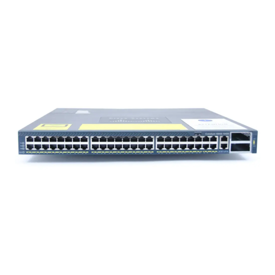
Catalyst 4900 Series Switch Applications Catalyst 4900 Series Switch Applications The Catalyst 4900 series switches (see designed for high-performance, high-density edge switching applications. They are fixed configuration switching solutions delivering 10/100/1000 connectivity on all ports, supporting hot swappable, redundant power supplies in a compact one rack-unit size for applications where space is limited. -
Page 25: Catalyst 4948 Switch Software Features
All three switches have a removable automatic variable speed fan tray for low noise operation at room temperature and removable and redundant 300 W AC or 300 W DC power supply provides fault-tolerance protection for the switch. See “Connecting AC Power to the Switch” section on page... -
Page 26: Catalyst 4948-10Ge And Catalyst 4928-10Ge Switch Software Features
• Support for 4,096 VLANs and 4,096 VLAN IDs • – Catalyst 4900 Series Switch Installation Guide Command-line interface (CLI) and Simple Network Management Protocol (SNMP) interfaces consistent with the Catalyst 4500 series switches Compatible development of new features with the Catalyst 4500 series... - Page 27 – Events, and History) on a per-port basis without the need for an optional RMON processing module Performance management information – Embedded CiscoView support – 78-18039-02 Catalyst 4948-10GE and Catalyst 4928-10GE Switch Software Features Catalyst 4900 Series Switch Installation Guide...
-
Page 28: Hardware System Features
The Catalyst 4900 series switches are high-performance dedicated Ethernet switches that fully integrate into the Catalyst family of switches using Catalyst 4500 series system software. The following is an overview of the Catalyst 4900 series hardware features: (Catalyst 4948 and 4948-10GE) 48 10BASE-T/100BASE-TX/1000BASE-T •... -
Page 29: Switch Components
(See Appendix A, “Specifications,” The Management port on the front panel is only operational when the switch is in rommon mode. When in use, it offers the same TCP/IP based management services available using inband access (Telnet, SNMP, etc.). IP address configuration using BOOTP is supported on the Management port;... - Page 30 Ca taly st WS -C4 948 10G E MGT port LED Figure 1-6 Management Port LED Catalyst 4900 Series Switch Installation Guide (Catalyst 4948) Management Port LEDs Detailed View (Catalyst 4948-10GE) Management Port LEDs Detailed View X2-1 X2-2 (Catalyst 4928-10GE) Management Port Detailed View...
-
Page 31: Front Panel Leds
A link status LED is below the management port. • 78-18039-02 Detailed View of the STATUS LEDs PS 1 PS 2 Fan LED FA N ST AT US Port LEDs STATUS LED Catalyst 4900 Series Switch Installation Guide Switch Components Figure 1-4 Figure 1-7) provide... - Page 32 Switch Components Table 1-1 describes LED functions. Table 1-1 STATUS Port 1-48 Catalyst 4900 Series Switch Installation Guide 1-10 LED Functions Color or State Description At startup, the switch performs a series of diagnostic tests: Green All tests pass A test other than an individual port test fails...
-
Page 33: Chassis Cooling
Fault detected or the on/off switch is set to off while the power supply is plugged in Chapter 2, “Site Planning.” shows the direction of airflow going in and out of the switch. Catalyst 4900 Series Switch Installation Guide Switch Components... -
Page 34: Power Supplies
For complete power specifications for the switch, see Appendix A, Note “Specifications.” The Catalyst 4900 series switches have two redundant internal 300 W AC or 300 W DC power supplies. The internal power supplies have individual power cords and status LEDs (PS1 and PS2 on the front panel). -
Page 35: Environmental Monitoring Of The Power Supplies
On/Off Switch Locations On/Off Switch The switch will start with only one power supply plugged in, but redundant failover and load sharing will not be available in this configuration. We recommend that you always connect both power supplies to separate AC or DC circuits for optimal power reliability. -
Page 36: Power Management For The Switch
AC and DC supplies are interchangeable. Power Management Modes Catalyst 4900 series switches support the redundant power management mode. In this mode, if both power supplies are operating normally, each provides from 20/80 to 45/55 percent of the total system power requirements at all times. If one power supply fails, the other unit increases power to 100 percent of the total power requirement. -
Page 37: Site Environmental Requirements
Site Planning This chapter describes how to prepare your site for installation of the switch and contains these sections: • Site Environmental Requirements, page 2-1 Site Power Requirements, page 2-2 • Grounding Requirements, page 2-6 • Safety Overview, page 2-7 •... -
Page 38: Site Power Requirements
Site Power Requirements The switch operates as a standalone system mounted in a rack in a secure wiring closet. It requires a dry, clean, well-ventilated, and air-conditioned environment. To ensure normal operation, maintain ambient airflow. If the airflow is blocked or restricted, or if the intake air is too warm, an overtemperature condition can occur. -
Page 39: Pre-Installation Requirements
• Pre-installation Requirements Follow these requirements when preparing your site for the switch installation: Connect each switch to separate wiring on a dedicated circuit; provide each • switch with its own branch circuit connection with sufficient overcurrent protection and direct grounding to the branch circuit. -
Page 40: Emi Recommendations
• • Strong EMI, especially when caused by lightning or radio transmitters, can destroy the signal drivers and receivers in the switch and can create an electrical hazard by conducting power surges through lines and into equipment. To predict and remedy strong EMI, you might need to consult RFI experts. - Page 41 Chapter 2 Site Planning You will also need to provide power to the switch with the appropriate AC power cord for your location. power supply. Table 2-1 AC-Input Power Cord Options Locale Part Number 300 W AC Power Supply North America CAB-US515-C15-US=...
-
Page 42: Grounding Requirements
M4x 8mm bolts and then to the central office (CO) or other interior ground system with number 6 AWG wire. The grounding connectors are on the right side of the chassis, and either one may be used. (See Catalyst 4900 Series Switch Installation Guide Length Plug Rating 8.2 ft (2.5 m) 250 VAC, 16 A... -
Page 43: Safety Overview
The plug-socket combination must be accessible at all times, because it serves as the main disconnecting device. Statement 1019 78-18039-02 Grounding Pad Locations (Catalyst 4849-10GE shown) Catalyst 4900 Series Switch Installation Guide Safety Overview Grounding pads Cataly st WS-C 4948 10GE... -
Page 44: Working Safely With Electricity
– Working Safely with Electricity Follow these basic guidelines when working with any electrical equipment: Locate the emergency power-off switch for the room in which you are • working before beginning installation. Disconnect all power and external cables before installing or removing a •... -
Page 45: Preventing Electrostatic Discharge Damage
ESD voltages on the body; ESD voltages on clothing can still cause damage. Site Planning Checklist Table 2-2 install the switch. Completing each activity helps to ensure a successful switch installation. 78-18039-02 ESD wrist strap connector... - Page 46 Cable and interface equipment evaluation: Cable type Connector type Cable distance limitations Interface equipment (transceivers) EMI evaluation: Distance limitations for signaling Site wiring RFI levels Catalyst 4900 Series Switch Installation Guide 2-10 Chapter 2 Site Planning Verified By Time Date 78-18039-02...
-
Page 47: Verifying The Contents
Installing the Switch This chapter describes how to install the Catalyst 4900 series switch. For first-time installations, perform the procedures in the following sections in the order listed. Verifying the Contents, page 3-1 • Rack-Mounting the Switch, page 3-2 •... -
Page 48: Rack-Mounting The Switch
3-2. Rack-Mounting the Switch A standard rack-mount kit is included for mounting the switch in a standard 19-inch (48.3 cm) equipment rack. A standard equipment rack has two unobstructed outer posts, a minimum depth between the front and rear mounting posts of 19.25 inches (48.9 cm), and a maximum depth of 32 inches (81.3 cm). -
Page 49: Rack-Mounting Guidelines
Mount the unit at the bottom of the rack if it is the only unit in the rack. Install heavier equipment in the lower half of the rack to maintain a low center of gravity and prevent the rack from becoming top-heavy and tipping over. Catalyst 4900 Series Switch Installation Guide Rack-Mounting the Switch Appendix A,... - Page 50 Ensure that the ambient temperature of the rack environment does not – exceed a maximum temperature of 104° F (40° C). Note that if the switch is installed in a closed or multiunit rack assembly, the ambient operating temperature of the rack environment might be higher than the ambient room temperature.
-
Page 51: Lifting The Chassis Safely
Installing the Switch Lifting the Chassis Safely The chassis is not intended to be moved frequently. Before you install the switch, ensure that your site is properly prepared so that you can avoid moving the chassis later to accommodate power sources and network connections. -
Page 52: Rack-Mounting The Switch
• Tape measure and level • Rack-Mounting the Switch The illustrations shown are of a Catalyst 4948-10GE switch. The process for the Note Catalyst 4948 and Catalyst 4928-10GE is identical. Follow these steps to install the switch in a rack. - Page 53 Table 3-1 Quantity Figure 3-2 Note can also attach the rear of the switch to the rack, depending on the configuration of your rack. Note that the L brackets connect the chassis to the rack. You can mount the Step 2 L brackets to the front or rear mounting holes of the chassis, depending on which end is in the front of the rack.
- Page 54 Figure 3-3 STATUS Attach the cable guide to the right or left side of the chassis mount. Step 4 Catalyst 4900 Series Switch Installation Guide Installing the Switch in the Rack Chapter 3 Installing the Switch Cataly st WS-C4 948 10GE...
-
Page 55: Connecting Ac Power To The Switch
Switch” section on page Connecting AC Power to the Switch Follow these steps and warnings when connecting power to a Catalyst 4900 series switch: Prior to connecting the power supply to a power source, ensure that all of the site... - Page 56 The PS1 or PS2 LED is red when the power supply is not functioning • normally. The on/off switch may be set to off while the power supply is plugged in, or the power supply may be defective and not providing DC power to the switch.
-
Page 57: Connecting Dc Power To The Switch
Hazardous voltage or energy may be present on DC power terminals. Always replace cover when terminals are not in service. Be sure uninsulated conductors are not accessible when cover is in place. Statement 1075 78-18039-02 Connecting DC Power to the Switch for troubleshooting Catalyst 4900 Series Switch Installation Guide 3-11... - Page 58 Connect the positive and negative power cables into the power supplies using a Step 4 number 2 Phillips screwdriver. The DC power cables may use AWG #10 to AWG #12 wire. Note Catalyst 4900 Series Switch Installation Guide 3-12 2-6. DC Power Supply Handle...
- Page 59 If the LEDs or show power command indicate a power or other system problem, Chapter 5, “Troubleshooting the Installation,” information. 78-18039-02 Connecting DC Power to the Switch for troubleshooting Catalyst 4900 Series Switch Installation Guide 3-13...
- Page 60 Chapter 3 Installing the Switch Connecting DC Power to the Switch Catalyst 4900 Series Switch Installation Guide 3-14 78-18039-02...
-
Page 61: Transceiver Modules
SFP modules with LC connectors, as shown in interface configuration mode command media-type sfp|rj45 can be used to configure the media type for these ports in the switch software and determines whether the SFP or the RJ-45 connector is used. The default is SFP. -
Page 62: Chapter 4 Transceiver Module
4-3. More general installation information is in the 10-Gigabit Ethernet X2 Transceiver Installation Note at the following location: http://www.cisco.com/en/US/products/hw/modules/ps5455/prod_installation_gu ide09186a00803469ed.html For compatibility information, refer to the 10-Gigabit Ethernet Transceiver Modules Compatibility Matrix at the following location: http://www.cisco.com/en/US/products/hw/modules/ps5455/products_device_sup port_table09186a00803857e7.html Catalyst 4900 Series Switch Installation Guide 78-18039-02... -
Page 63: X2 Modules
MMF cable, an effect known as Differential Mode Delay (DMD) might occur. See the Catalyst 4500 Series Module Installation Guide for more information. 78-18039-02 Connecting SC Connectors to the X2 Module Ca ta lys t W S- C4 94 8 10 GE X2-1 X2-2 Catalyst 4900 Series Switch Installation Guide X2 Modules... - Page 64 For either the top or bottom connector, forcing a module could potentially damage both the module and the switch. Catalyst 4900 Series Switch Installation Guide Installing the 10-Gigabit Ethernet X2 Module l y s...
-
Page 65: Module Maintenance Guidelines
Therefore, the connector must be precisely aligned, and the connector interface must be absolutely free of trapped foreign material. 78-18039-02 Cleaning the Fiber-Optic Connectors Catalyst 4900 Series Switch Installation Guide... -
Page 66: Cleaning The Fiber-Optic Connectors
Remove any residual dust from the faceplate with clean, dry, oil-free compressed air. Invisible laser radiation may be emitted from disconnected fibers or Warning connectors. Do not stare into beams or view directly with optical instruments. Statement 1051 Catalyst 4900 Series Switch Installation Guide Chapter 4 Transceiver Modules 78-18039-02... -
Page 67: Additional Guidelines
Cover the connectors and adapters to keep the inside of the adapters or the • surface of the connectors from getting dirty when you are not using the connectors or while you are cleaning the chassis. 78-18039-02 Cleaning the Fiber-Optic Connectors Catalyst 4900 Series Switch Installation Guide... - Page 68 Chapter 4 Transceiver Modules Cleaning the Fiber-Optic Connectors Catalyst 4900 Series Switch Installation Guide 78-18039-02...
-
Page 69: Troubleshooting The Installation
DC-line voltages. For configuration questions or problems, refer to the software configuration guide Note or the command reference publication. 78-18039-02 C H A P T E R Catalyst 4900 Series Switch Installation Guide... -
Page 70: Getting Started
There are no installation adjustments that you can make if the fan assembly does not function properly at the initial startup. Catalyst 4900 Series Switch Installation Guide “Troubleshooting the Power Supply” section on page Chapter 5 Troubleshooting the Installation 5-5.) -
Page 71: Identifying Startup Problems
Chapter 5 Troubleshooting the Installation Identifying Startup Problems When you connect the power cords to the switch, follow these steps: Flip the power switches to the on position (AC powered systems only). Step 1 Step 2 Verify that power is available to the power supplied from the site AC or DC source. - Page 72 Step 2 The STATUS LED flashes yellow during diagnostic boot tests. It is green • when the switch is operational (online). If the system software is unable to start up, this LED stays orange. Catalyst 4900 Series Switch Installation Guide...
-
Page 73: Troubleshooting The Power Supply
Troubleshooting the Power Supply Follow these steps to help isolate a power subsystem problem: Verify that the power supply is plugged in and that the on/off switch is set to ON Step 1 (if the power supply is an AC supply). -
Page 74: Contacting Customer Service
Brief description of the problem • Brief explanation of the steps you have already taken to isolate and resolve • the problem Figure 5-1 SN: AAANNNNXXXX Catalyst 4900 Series Switch Installation Guide Chapter 5 Figure 5-1) Serial Number Location Troubleshooting the Installation 78-18039-02... -
Page 75: Specifications
Console Port Pinouts Direction Description output request to send output data terminal ready output transmit data — — — — input receive data input data set ready input clear to send Catalyst 4900 Series Switch Installation Guide lists the console port pinouts. -
Page 76: Appendix A Specification
Table A-3 Table A-3 Signal TXRX0P TXRX0N TXRX1P TXRX2P TXRX2N TXRX1N TXRX3P TXRX3N Catalyst 4900 Series Switch Installation Guide Table A-2 lists the 10/100BASE-T port pinouts. 10/100BASE-T Port Pinouts Direction Description input receive data input receive data output transmit data —... -
Page 77: Catalyst 4900 Series Switch Specifications
Dimensions (H x W x D) Weight Airflow AC Power Minimum input 78-18039-02 shows Catalyst 4900 series switch specifications. Specification 32°F (0°C) to 104°F (40°C) –40 to 167°F (–40 to 75°C) 10% to 90% 5% to 95% –60 to 2000 m... -
Page 78: Catalyst 4900 Series Switch Specifications
Catalyst 4900 Series Switch Specifications Table A-4 Catalyst 4900 Series Switch Specifications (continued) Item Power supply output AC-input AC frequency Output current Peak current Inrush value Output voltage Input KVA rating DC Power Minimum input Power supply output DC-input Output current... -
Page 79: Initial Configuration For The Switch
If you are using a DC power supply, see the Note section on page 3-11 power supply. You need to provide the Category 5 straight-through cables to connect the switch Note ports to other Ethernet devices. 78-18039-02 A P P E N D I X “Connecting DC Power to the Switch”... -
Page 80: Console Port
Using the supplied RJ-45-to-DB-9 adapter cable, insert the RJ-45 connector into Step 1 the console port that is located on the front of the switch, as shown in Attach the DB-9 female DTE of the adapter cable to a PC serial port, or attach an Step 2 appropriate adapter to the terminal. -
Page 81: Starting The Terminal-Emulation Software
If you are using an AC power supply, connect one end of the supplied AC power Step 1 cord to the power connector on the switch rear panel, and then connect the other end of the power cable to a grounded AC outlet. (See... -
Page 82: Entering The Initial Configuration Information
LEDs remain green (see the more information). If the switch fails POST, the system LED turns amber. POST failures are usually fatal. Call Cisco Systems if your switch does not pass Note POST. If you started the terminal-emulation program before you powered on your switch, the PC or terminal displays the bootloader sequence. -
Page 83: Performing The Initial Configuration
Configure a host name for the switch, and press Return. Step 5 Switch (config)# hostname Switch1 Configure the system prompt for the switch, and press Return. To remove the new Step 6 prompt and return the prompt to its default, use the no prompt command. - Page 84 !--- Output suppressed. Verify the IP information by using the show ip interface brief and show ip route Step 14 commands. Switch1# show ip interface brief Catalyst 4900 Series Switch Installation Guide Appendix B Initial Configuration for the Switch 78-18039-02...
- Page 85 You have now completed the initial configuration of the switch. To use the CLI to perform additional configuration or management tasks, enter commands at the Switch> prompt through the console port by using a terminal program or through the network by using Telnet. For configuration information, refer to the switch software configuration guide or the switch command reference.
- Page 86 Appendix B Initial Configuration for the Switch Entering the Initial Configuration Information Catalyst 4900 Series Switch Installation Guide 78-18039-02...
-
Page 87: Translated Safety Warnings
SAVE THESE INSTRUCTIONS This document includes the following sections: Translated Safety Warnings, page C-2 • Regulatory Standards Compliance, page C-39 • European Directives, page C-42 • 78-18039-02 A P P E N D I X Catalyst 4900 Series Switch Installation Guide... -
Page 88: Translated Safety Warnings
Før noen av disse prosedyrene utføres, kontroller at strømmen er frakoblet likestrømkretsen. Antes de executar um dos seguintes procedimentos, certifique-se que Aviso desligou a fonte de alimentação de energia do circuito de corrente contínua. Catalyst 4900 Series Switch Installation Guide Appendix C Compliance Information and Translated Safety Warnings 78-18039-02... - Page 89 Antes de executar qualquer um dos procedimentos a seguir, verifique se a energia foi removida do circuito DC. Advarsel Før du udfører nogen af følgende procedurer, skal du sikre dig, at der ikke er strøm til jævnstrømskredsløbet. Catalyst 4900 Series Switch Installation Guide 78-18039-02...
-
Page 90: Statement 1004—Installation Instructions
Leia as instruções de instalação antes de ligar o sistema à fonte de energia. ¡Advertencia! Lea las instrucciones de instalación antes de conectar el sistema a la red de alimentación. Varning! Läs installationsanvisningarna innan du kopplar systemet till strömförsörjningsenheten. Catalyst 4900 Series Switch Installation Guide 78-18039-02... - Page 91 Appendix C Compliance Information and Translated Safety Warnings Translated Safety Warnings Catalyst 4900 Series Switch Installation Guide 78-18039-02...
-
Page 92: Statement 1006—Chassis Warning For Rack-Mounting And Servicing
• Jos telinettä varten on vakaimet, asenna ne ennen laitteen asettamista telineeseen tai sen huoltamista siinä. Catalyst 4900 Series Switch Installation Guide Appendix C Compliance Information and Translated Safety Warnings Statement 1006... - Page 93 • Se il supporto è dotato di dispositivi stabilizzanti, installare tali dispositivi prima di montare o di procedere alla manutenzione dell’unità nel supporto. 78-18039-02 Translated Safety Warnings Catalyst 4900 Series Switch Installation Guide...
- Page 94 • Si el bastidor dispone de dispositivos estabilizadores, instalar éstos antes de montar o proceder al mantenimiento del equipo instalado en el bastidor. Catalyst 4900 Series Switch Installation Guide Appendix C Compliance Information and Translated Safety Warnings 78-18039-02...
- Page 95 Ved montering af denne enhed i et delvist fyldt rack, skal enhederne installeres fra bunden og opad med den tungeste enhed nederst. • Hvis racket leveres med stabiliseringsenheder, skal disse installeres for enheden monteres eller serviceres i racket. 78-18039-02 Translated Safety Warnings Catalyst 4900 Series Switch Installation Guide...
- Page 96 Translated Safety Warnings • • • • • • Catalyst 4900 Series Switch Installation Guide C-10 Appendix C Compliance Information and Translated Safety Warnings 78-18039-02...
- Page 97 Al l ot h er t r ademarks ment i o ned i n t h i s document or Websi t e are t h e propert y of t h ei r respect i v e owners. The use of t h e word part n er does not i m pl y a part n ershi p rel a t i o nshi p bet w een Ci s co and any ot h er company. ( 0 705R) 78-18039-02 Translated Safety Warnings Catalyst 4900 Series Switch Installation Guide C-11...
- Page 98 Appendix C Compliance Information and Translated Safety Warnings Translated Safety Warnings Catalyst 4900 Series Switch Installation Guide C-12 78-18039-02...
- Page 99 Appendix C Compliance Information and Translated Safety Warnings Translated Safety Warnings Catalyst 4900 Series Switch Installation Guide C-13 78-18039-02...
-
Page 100: Statement 1008—Class 1 Laser Product
Appendix C Compliance Information and Translated Safety Warnings Translated Safety Warnings Statement 1008—Class 1 Laser Product Class 1 laser product. Statement 1008 Warning Waarschuwing Klasse-1 laser produkt. Catalyst 4900 Series Switch Installation Guide C-14 78-18039-02... - Page 101 Laserprodukt av klasse 1. Aviso Produto laser de classe 1. ¡Advertencia! Producto láser Clase I. Varning! Laserprodukt av klass 1. Aviso Produto a laser de classe 1. Advarsel Klasse 1 laserprodukt. 78-18039-02 Translated Safety Warnings Catalyst 4900 Series Switch Installation Guide C-15...
-
Page 102: Statement 1011—Staring Into Laser Beam
Älä katso säteeseen äläkä tarkastele sitä suoraan optisen laitteen avulla. Attention Ne pas fixer le faisceau des yeux, ni l'observer directement à l'aide d'instruments optiques. Warnung Nicht direkt in den Strahl blicken und ihn nicht direkt mit optischen Geräten prüfen. Catalyst 4900 Series Switch Installation Guide C-16 78-18039-02... - Page 103 Não olhe fixamente para o raio, nem olhe para ele directamente com Aviso instrumentos ópticos. ¡Advertencia! No mirar fijamente el haz ni observarlo directamente con instrumentos ópticos. Varning! Rikta inte blicken in mot strålen och titta inte direkt på den genom optiska instrument. Catalyst 4900 Series Switch Installation Guide C-17 78-18039-02...
-
Page 104: Statement 1017—Restricted Area
Esta unidade foi concebida para instalação em áreas de acesso restrito. Uma área de acesso restrito é uma área à qual apenas tem acesso o pessoal de serviço autorizado, que possua uma ferramenta, chave e fechadura especial, ou qualquer outra forma de segurança. Catalyst 4900 Series Switch Installation Guide C-18 78-18039-02... - Page 105 Denne enhed er beregnet til installation i områder med begrænset adgang. Der kan kun opnås adgang til et begrænset område ved at bruge et særligt stykke værktøj, lås og nøgle, eller en anden form for sikkerhed. Catalyst 4900 Series Switch Installation Guide C-19 78-18039-02...
- Page 106 Appendix C Compliance Information and Translated Safety Warnings Translated Safety Warnings Catalyst 4900 Series Switch Installation Guide C-20 78-18039-02...
-
Page 107: Statement 1019—Main Disconnecting Device
Warnung Der Netzkabelanschluß am Gerät muß jederzeit zugänglich sein, weil er als primäre Ausschaltvorrichtung dient. Avvertenza Il gruppo spina-presa deve essere sempre accessibile, poiché viene utilizzato come dispositivo di scollegamento principale. Catalyst 4900 Series Switch Installation Guide C-21 78-18039-02... - Page 108 El conjunto de clavija y toma ha de encontrarse siempre accesible ya que hace las veces de dispositivo de desconexión principal. Varning! Man måste alltid kunna komma åt stickproppen i uttaget, eftersom denna koppling utgör den huvudsakliga frånkopplingsanordningen. Catalyst 4900 Series Switch Installation Guide C-22 78-18039-02...
-
Page 109: Statement 1024—Ground Conductor
Se non si è certi della disponibilità di un adeguato collegamento di messa a terra, richiedere un controllo elettrico presso le autorità competenti o rivolgersi a un elettricista. Catalyst 4900 Series Switch Installation Guide C-23 78-18039-02... - Page 110 Denna utrustning måste jordas. Koppla aldrig från jordledningen och använd aldrig utrustningen utan en på lämpligt sätt installerad jordledning. Om det föreligger osäkerhet huruvida lämplig jordning finns skall elektrisk besiktningsauktoritet eller elektriker kontaktas. Catalyst 4900 Series Switch Installation Guide C-24 78-18039-02...
-
Page 111: Statement 1030—Equipment Installation
Personal gestattet werden. Avvertenza Questo apparato può essere installato, sostituito o mantenuto unicamente da un personale competente. Advarsel Bare opplært og kvalifisert personell skal foreta installasjoner, utskiftninger eller service på dette utstyret. Catalyst 4900 Series Switch Installation Guide C-25 78-18039-02... - Page 112 Somente uma equipe treinada e qualificada tem permissão para instalar, substituir ou dar manutenção a este equipamento. Advarsel Kun uddannede personer må installere, udskifte komponenter i eller servicere dette udstyr. Catalyst 4900 Series Switch Installation Guide C-26 Appendix C Compliance Information and Translated Safety Warnings 78-18039-02...
-
Page 113: Statement 1040—Product Disposal
Statement 1040 Waarschuwing Het uiteindelijke wegruimen van dit product dient te geschieden in overeenstemming met alle nationale wetten en reglementen. Varoitus Tämä tuote on hävitettävä kansallisten lakien ja määräysten mukaisesti. Catalyst 4900 Series Switch Installation Guide C-27 78-18039-02... - Page 114 O descarte definitivo deste produto deve estar de acordo com todas as leis e regulamentações nacionais. Advarsel Endelig bortskaffelse af dette produkt skal ske i henhold til gældende love og regler. Catalyst 4900 Series Switch Installation Guide C-28 Appendix C Compliance Information and Translated Safety Warnings 78-18039-02...
- Page 115 Appendix C Compliance Information and Translated Safety Warnings Translated Safety Warnings Catalyst 4900 Series Switch Installation Guide C-29 78-18039-02...
-
Page 116: Statement 1045—Short-Circuit Protection
Aviso Este produto requer proteção contra curto-circuitos (sobreintensidade de corrente), que deve estar instalada nos edifícios. Instale apenas de acordo com as normas de instalação elétrica nacionais e locais. Catalyst 4900 Series Switch Installation Guide C-30 78-18039-02... - Page 117 Advarsel Dette produkt kræver beskyttelse mod kortslutning (overstrøm). Dette skal være en del elinstallationen i bygningen. Installation skal ske i overensstemmelse med nationale og lokale ledningsregler. Catalyst 4900 Series Switch Installation Guide C-31 78-18039-02...
- Page 118 Appendix C Compliance Information and Translated Safety Warnings Translated Safety Warnings Catalyst 4900 Series Switch Installation Guide C-32 78-18039-02...
-
Page 119: Statement 1051—Laser Radiation
à l'œil. Ne regardez jamais directement les faisceaux laser à l'œil nu, ni d'ailleurs avec des instruments optiques. Warnung Unterbrochene Fasern oder Steckerverbindungenkönnen unsichtbare Laserstrahlung abgeben. Blicken Sie weder mit bloßem Auge noch mit optischen Instrumenten direkt in Laserstrahlen. Catalyst 4900 Series Switch Installation Guide C-33 78-18039-02... - Page 120 Não fixe o olhar nos feixes e nem olhe diretamente com instrumentos ópticos. Advarsel Usynlig laserstråling kan forekomme fra brugte fibre eller stik. Stir ikke ind i stråler eller direkte med optiske instrumenter. Catalyst 4900 Series Switch Installation Guide C-34 Appendix C Compliance Information and Translated Safety Warnings 78-18039-02...
- Page 121 Appendix C Compliance Information and Translated Safety Warnings Translated Safety Warnings Catalyst 4900 Series Switch Installation Guide C-35 78-18039-02...
-
Page 122: Statement 1074—Comply With Local And National Electrical Codes
Die Installation der Geräte muss den Sicherheitsstandards entsprechen. Avvertenza L'installazione dell'impianto deve essere conforme ai codici elettrici locali e nazionali. Advarsel Installasjon av utstyret må samsvare med lokale og nasjonale elektrisitetsforskrifter. Catalyst 4900 Series Switch Installation Guide C-36 Appendix C Compliance Information and Translated Safety Warnings 78-18039-02... -
Page 123: Statement 1075—Hazardous Voltage Or Energy Present On Dc Power Terminals
Op DC-aansluitingspunten kunnen zich gevaarlijke voltages of energieën Waarschuwing voordoen. Plaats altijd de afsluiting wanneer de aansluitingspunten niet worden gebruikt Zorg ervoor dat blootliggende contactpunten niet toegankelijk zijn wanneer de afsluiting is geplaatst. 78-18039-02 Translated Safety Warnings Catalyst 4900 Series Switch Installation Guide C-37... - Page 124 Varning! Farlig spänning eller skadlig energi kan finnas i likströmsterminalerna. Sätt alltid tillbaka höljet när terminalerna inte används. Försäkra att inga oisolerade ledare kan nås när höljet sitter på plats. Catalyst 4900 Series Switch Installation Guide C-38 78-18039-02...
-
Page 125: Regulatory Standards Compliance
Class A Regulatory Standards Compliance Standard Products with the CE Marking indicate compliance with the 1999/5/EC directive, which includes the safety and EMC standards listed. UL 60950-1 CAN/CSA-C22.2 No. 60950-1 Catalyst 4900 Series Switch Installation Guide Regulatory Standards Compliance C-39... - Page 126 Regulatory Standards Compliance Table C-1 Specification Table C-2 Specification NEBS Criteria Levels Verizon NEBS Compliance Catalyst 4900 Series Switch Installation Guide C-40 Appendix C Compliance Information and Translated Safety Warnings Class A Regulatory Standards Compliance (continued) Standard EN 60950-1 IEC 60950-1...
- Page 127 Shielded cable grounded at both ends specified for copper telecom ports. Caution The Catalyst 4900 Series Switches have AC power ports that are intended for deployments where an external Surge Protective Device (SPD) is utilized at the AC power service equipment (see definition in National Electric Code).
-
Page 128: European Directives
[Czech]: Dansk Dette udstyr er i overensstemmelse med de væsentlige krav og andre [Danish]: relevante bestemmelser i Direktiv 1999/5/EF. Catalyst 4900 Series Switch Installation Guide C-42 Appendix C Compliance Information and Translated Safety Warnings GR-1089 Installation and Caution Instructions (continued) - Page 129 Dit apparaat voldoet aan de essentiele eisen en andere van toepassing zijnde [Dutch]: bepalingen van de Richtlijn 1999/5/EC. Malti [Maltese]: Magyar [Hungarian]: Norsk Dette utstyret er i samsvar med de grunnleggende krav og andre relevante [Norwegian]: bestemmelser i EU-direktiv 1999/5/EF. 78-18039-02 European Directives Catalyst 4900 Series Switch Installation Guide C-43...
-
Page 130: As Amended By Directive 93/68/Eec
Statement 275—Declaration of Conformity with Regard to the Directives 73/23/EEC and 89/336/EEC as amended by Directive 93/68/EEC For specifics about which standards have been applied, refer to the Declaration of Conformity. Catalyst 4900 Series Switch Installation Guide C-44 Appendix C Compliance Information and Translated Safety Warnings 78-18039-02... - Page 131 Dette utstyret samsvarer med de vesentligste kravene og andre regler i direktivene 73/23/EEC og 89/336/EEC samt i tilleggsdirektiv 93/68/EEC. Português: Este equipamento satisfaz os requisitos essenciais e outras provisões das Directivas 73/23/EEC e 89/336/EEC, conforme amendados pela Directiva 93/68/EEC. Catalyst 4900 Series Switch Installation Guide C-45 78-18039-02...
-
Page 132: Emc Class A Notices And Warnings
In that event, your right to use the equipment may be limited by FCC regulations, and you may be required to correct any interference to radio or television communications at your own expense. Catalyst 4900 Series Switch Installation Guide C-46 Appendix C... -
Page 133: Class A Notice For Canada
Il s'agit d'un produit de classe A. Dans un environnement local, ce produit peut entraîner des perturbations radioélectriques, auquel cas l'utilisateur devra éventuellement prendre des mesures adéquates. 78-18039-02 EMC Class A Notices and Warnings Catalyst 4900 Series Switch Installation Guide C-47... - Page 134 Varning! Detta är en klass A-produkt. Denna produkt kan orsaka radiostörningar inomhus. Det kan då vara ett krav att användaren vidtar lämpliga åtgärder. Catalyst 4900 Series Switch Installation Guide C-48 78-18039-02...
- Page 135 Appendix C Compliance Information and Translated Safety Warnings EMC Class A Notices and Warnings Catalyst 4900 Series Switch Installation Guide C-49 78-18039-02...
-
Page 136: Statement 191—Vcci Class A Warning For Japan
Council for Interference by Information Technology Equipment (VCCI). If this equipment is used in a domestic environment, radio disturbance may arise. When such trouble occurs, the user may be required to take corrective actions. Catalyst 4900 Series Switch Installation Guide C-50 78-18039-02... -
Page 137: Statement 256—Class A Warning For Hungary
The seller or buyer should be aware of this. If this type was sold or purchased by mistake, it should be replaced with a residential-use type. 78-18039-02 EMC Class A Notices and Warnings Catalyst 4900 Series Switch Installation Guide C-51... -
Page 138: Statement 257—Class A Notice For Taiwan And Other Traditional Chinese Markets
Statement 257 Statement 371—Power Cable and AC Adapter Catalyst 4900 Series Switch Installation Guide C-52 Appendix C Compliance Information and Translated Safety Warnings... - Page 139 I N D E X cable guide chassis dimensions weight checklist, site planning cleaning guidelines console port connecting to location pinouts customer service dimensions, chassis documentation audience i-ix conventions i-xi organization i-ix related Catalyst 4900 Series Switch Installation Guide IN-1...
-
Page 140: Management Port
DC systems hardware description power supply 1-12 heat dissipation determining installation connecting to a power source Catalyst 4900 Series Switch Installation Guide IN-2 starting the terminal-emulation software installing the switch guidelines lifting procedure safety overview tools required... - Page 141 EMI recommendations environmental requirements general requirements overview 1-13 warnings and cautions software documentation specifications AC Power DC Power environmental switching components startup sequence status LED system specifications temperature thresholds terminal-emulation software Catalyst 4900 Series Switch Installation Guide 1-10 Index IN-3...
- Page 142 Index traffic ports troubleshooting contacting customer service initial boot methodology power supply 5-4, 5-5 startup typographical conventions i-xi warnings translated safety weight chassis Catalyst 4900 Series Switch Installation Guide IN-4 78-18039-02...