
Related Manuals for IBM G8316


Summary of Contents for IBM G8316
- Page 1 IBM System Networking RackSwitch G8316, Type 8036 and Type 1611-16E Installation Guide...
- Page 3 IBM System Networking RackSwitch G8316, Type 8036 and Type 1611-16E Installation Guide...
- Page 4 Note: Before using this information and the product it supports, read the Warranty Information document, Appendix B, “Notices,” on page 57 and the Important Notices document. Read the IBM System Safety Notices document and the License Agreement for Machine Code (LAMC) document on the IBM Documentation CD. Read the IBM Systems Environmental Notices and Users Guide document on the Environmental Notices CD.
- Page 5 Prima di installare questo prodotto, leggere le Informazioni sulla Sicurezza. Les sikkerhetsinformasjonen (Safety Information) før du installerer dette produktet. Antes de instalar este produto, leia as Informações sobre Segurança. Antes de instalar este producto, lea la información de seguridad. © Copyright IBM Corp. 2014...
- Page 6 Do not open any cover or barrier that contains this label. (L001) DANGER Rack-mounted devices are not to be used as shelves or work spaces. (L002) IBM System Networking RackSwitch G8316, Type 8036 and Type 1611-16E: Installation Guide...
- Page 7 DANGER Multiple power cords. The product might be equipped with multiple power cords. To remove all hazardous voltages, disconnect all power cords. (L003) Safety...
- Page 8 It is the responsibility of the customer to ensure that the outlet is correctly wired and grounded to prevent an electrical shock. (D004) IBM System Networking RackSwitch G8316, Type 8036 and Type 1611-16E: Installation Guide...
- Page 9 Connect power to this unit only with the IBM provided power cord. Do not use the IBM provided power cord for any other product. v Do not open or service any power supply assembly. v Do not connect or disconnect any cables or perform installation, maintenance, or reconfiguration of this product during an electrical storm.
- Page 10 Incorporate a readily available approved and rated disconnect device in the field wiring. (C033) Table 1. Electrical connections Circuit breaker rating Minimum: 20 amps Maximum: 20 amps viii IBM System Networking RackSwitch G8316, Type 8036 and Type 1611-16E: Installation Guide...
- Page 11 Table 1. Electrical connections (continued) Wire size 16 AWG, 1.31 mm2 Wiring terminal screw torque v inch-pounds newton-meters (Nm) Safety...
- Page 12 It is the responsibility of the customer to ensure that the outlet is correctly wired and grounded to prevent an electrical shock. (R001 part 1 of 2) IBM System Networking RackSwitch G8316, Type 8036 and Type 1611-16E: Installation Guide...
- Page 13 CAUTION: v Do not install a unit in a rack where the internal rack ambient temperatures will exceed the manufacturer’s recommended ambient temperature for all your rack-mounted devices. v Do not install a unit in a rack where the air flow is compromised. Ensure that air flow is not blocked or reduced on any side, front, or back of a unit used for air flow through the unit.
- Page 14 IBM System Networking RackSwitch G8316, Type 8036 and Type 1611-16E: Installation Guide...
-
Page 15: Table Of Contents
Chapter 1. Introduction ..... . 1 The IBM Documentation CD ....1 Hardware and software requirements . - Page 16 ....55 How to send Dynamic System Analysis data to IBM ... 56 Using the documentation .
-
Page 17: Chapter 1. Introduction
Command Reference and the product release notes. The RackSwitch G8316 is a rackable aggregation switch with unmatched line-rate Layer 2/3 performance. The RackSwitch uses a wire-speed, non-blocking switching fabric that provides simultaneous wire-speed transport of multiple packets at low latency on all ports. -
Page 18: Hardware And Software Requirements
This section provides an overview of RackSwitch G8316 features. Performance v 12800 Gbps throughput (full duplex), non-blocking switching architecture v 100% line rate Management Features v Clients – Industry standard command-line interface (ISCLI) IBM System Networking RackSwitch G8316, Type 8036 and Type 1611-16E: Installation Guide... - Page 19 – Browser-based Interface (BBI) – System Networking Element Manager v Protocols – SNMP v1, v2, v3 – Remote Monitoring (RMON) – Network Time Protocol (NTP) support – DHCP v Software upgrades – Dual software images – Upgrade via serial, browser, or TFTP Software Features v Security –...
-
Page 20: Switch Components
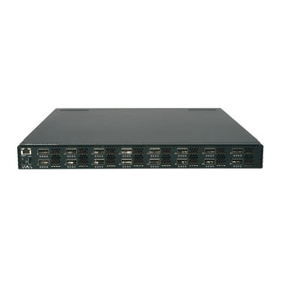
– Heavy duty 2-post rack mounting brackets and screws ® – IBM iDataPlex rack mounting brackets and screws – IBM System Networking Adjustable 19" 4-post rail kit (for Power and System x racks) includes mounting brackets and screws v Hot-swap power supply v Hot-swap fans Switch unit The RackSwitch G8316 switch unit is a 1U rack-mountable gigabit Ethernet switch. - Page 21 RJ-45 Port Mgmt Reset Button USB Port RS-232 Port System Status LEDs Figure 2. IBM RackSwitch G8316 front panel detail IEC320 IEC320 Power Connector Power Connector Power Supply Power Supply Fan Modules Module Module Figure 3. IBM RackSwitch G8316 rear panel Reset button The Reset button is recessed within a hole on the front panel.
-
Page 22: Switch Ports
DACs are labelled A, B, C, and D, which correspond to the first, second, third, and fourth ports in the port range. For the available QSFP+ transceivers and DACs for the switch, see https://www-01.ibm.com/products/hardware/configurator/americas/bhui/launchNI.wss. IBM System Networking RackSwitch G8316, Type 8036 and Type 1611-16E: Installation Guide... - Page 23 RJ-45 management port The 10/100/1000BASE-T management port (RJ-45) is located on the front panel. These management ports support in-line management and Control Plane Stacking. The following table describes the RJ-45 connector pin assignments. Table 2. RJ-45 Port pin assignments Pin number Signal Description BI DA+...
-
Page 24: Switch Leds
The system LEDs are described in the following table. Table 5. System LEDs Symbol Description Service indicator Power supplies and power input status Fans status Stacking indicator The following table describes the system LEDs. IBM System Networking RackSwitch G8316, Type 8036 and Type 1611-16E: Installation Guide... - Page 25 Table 6. System LED descriptions Function Service Power supply Fans Stacking Total Power Failure Service Required Flash blue Flash green (Note 1) Flash green (Note 2) Flash green or steady green (Note 3 Power Supplies OK Not applicable Steady green Not applicable Not applicable Power Supply Failure...
-
Page 26: Technical Specifications
The power specifications for the RackSwitch are listed in the following table. Table 11. AC power specifications Specification Measurement Number of power supplies 2 (1+1 load sharing/redundant) AC-input frequency (universal) 50 - 60 Hz AC-input voltage (universal) 100-240 VAC IBM System Networking RackSwitch G8316, Type 8036 and Type 1611-16E: Installation Guide... - Page 27 Table 11. AC power specifications (continued) Specification Measurement AC inrush current 15 A AC-input current (typical) 2.35 A (RMS) @ 120 V 1.22 A (RMS) @ 230 V AC-input current (maximum) 3.125 A (RMS) @ 120 V 1.630 A (RMS) @ 230 V Power supply rated output power 450 W each System power dissipation (typical)
- Page 28 IBM System Networking RackSwitch G8316, Type 8036 and Type 1611-16E: Installation Guide...
-
Page 29: Chapter 2. Installing The Rackswitch And Options
This chapter describes the how to install the RackSwitch chassis and the associated RackSwitch components. v “Installing the RackSwitch in the standard equipment rack” on page 17 v “Installing the RackSwitch in the IBM iDataPlex rack” on page 20 ® v “Installing the RackSwitch in the IBM System x or Power rack”... -
Page 30: Required Tools
The basic RackSwitch G8316 package contains the following items: v G8316 switch unit (one of the following): – G8316 (front-to-rear) provides front-to-rear air flow – G8316 (rear-to-front) provides rear-to-front airflow IBM System Networking RackSwitch G8316, Type 8036 and Type 1611-16E: Installation Guide... -
Page 31: Environmental Requirements
This product does not contain any user-serviceable parts. Do not remove the cover of this device. The G8316 AC power model is designed to work with single-phase power systems that have a grounded neutral conductor. To reduce the risk of electric shock, always plug the power cord into a grounded power outlet. - Page 32 2. Attach all cables to the devices. 3. Attach the signal cables to the connectors. 4. Attach the power cords to the outlets. 5. Turn on the devices. (D005) IBM System Networking RackSwitch G8316, Type 8036 and Type 1611-16E: Installation Guide...
-
Page 33: Handling Static-Sensitive Devices
This section describes how to install the RackSwitch in the standard 19-inch equipment rack. For information about mounting the RackSwitch in other rack types, see the following sections: v “Installing the RackSwitch in the IBM iDataPlex rack” on page 20 ® v “Installing the RackSwitch in the IBM System x or Power rack”... - Page 34 4. Use the M6 screws, washers, and clip nuts (or cage nuts) to secure the switch unit to the rack. Torque the screws to approximately 5.7 Nm +/- 0.1 Nm (50 inch-pounds). IBM System Networking RackSwitch G8316, Type 8036 and Type 1611-16E: Installation Guide...
- Page 35 5. Connect all cables. 6. Initialize the switch, see Chapter 4, “Initializing the RackSwitch,” on page 43. Attention: If this is a switch replacement, make sure the VPD is updated to avoid losing the licensed electronic entitlement data of the RackSwitch. For more information, see “Configuring Vital Product Data after a switch replacement”...
-
Page 36: Installing The Rackswitch In The Ibm Idataplex Rack
Installing the RackSwitch in the IBM iDataPlex rack This section describes how to install the RackSwitch in an IBM iDataPlex rack. The iDataPlex mounting kit allows the switch to be mounted either vertically or horizontally. For information about mounting the RackSwitch in other rack types, see the following sections: v “Installing the RackSwitch in the standard equipment rack”... - Page 37 3. Slide the RackSwitch into the rack. 4. Use the M6 washers and screws are used to mount the switch unit into the rack. Torque the screws to approximately 5.7 Nm +/- 0.1 Nm (50 inch-pounds). 5. Use the M6 washers, screws, and clip nuts are used to attach the alignment plate.
-
Page 38: Installing The Rackswitch In The Ibm System X Or Power Rack
Installing the RackSwitch in the IBM System x or Power rack This section provides how to install the RackSwitch in an IBM System Networking Adjustable 19” 4-post rail kit (for Power and System x racks). For information about mounting the RackSwitch in other rack types, see the following sections: v “Installing the RackSwitch in the standard equipment rack”... - Page 39 To install the RackSwitch in the IBM System Networking adjustable 19” 4-post rack (for Power and System x racks), complete the following steps: 1. Locate and record the product switch information to configure and register your product and set aside. See “Before installing the RackSwitch” on page 13.
- Page 40 5. Use the M6 washers, screws, and clip nuts to attach the filler plate to the rear mounting brackets. Torque the screws to approximately 5.7 Nm +/- 0.1 Nm (50 inch-pounds). IBM System Networking RackSwitch G8316, Type 8036 and Type 1611-16E: Installation Guide...
-
Page 41: Installing The 1U Air Duct Option In A Rack
6. Use the M3.5 screws to secure the rear brackets to the front brackets. Torque the screws to approximately 1.1 Nm +/- 0.1 Nm (10 inch-pounds). 10 11 7. Connect all the cables. 8. Initialize the switch, see Chapter 4, “Initializing the RackSwitch,” on page 43. Attention: If this is a switch replacement, make sure the VPD is updated to avoid losing the licensed electronic entitlement data of the RackSwitch. - Page 42 Screw, slotted, M3.5, 7 mm, flanged hex head DANGER Rack-mounted devices are not to be used as shelves or work spaces. (L002) IBM System Networking RackSwitch G8316, Type 8036 and Type 1611-16E: Installation Guide...
- Page 43 To install the 1U air duct option in a 19" rack, complete the following steps. 1. Loosen and remove the mounting screws from the both sides of the mounting rail and set aside to reuse to secure the foam carrier. Foam carrier snug against rear of unit Reuse mounting screws Half shear...
-
Page 44: Installing A Qsfp+ Transceiver
The QSFP+ ports accept approved QSFP+ transceivers. The QSFP+ optical transceiver provides an MTP cable connector for connecting to external ports. IBM System Networking RackSwitch G8316, Type 8036 and Type 1611-16E: Installation Guide... - Page 45 CAUTION: This product might contain one or more of the following devices: CD-ROM drive, DVD-ROM drive, DVD-RAM drive, or laser module, which are Class 1 laser products. Note the following information: v Do not remove the covers. Removing the covers of the laser product could result in exposure to hazardous laser radiation.
- Page 46 IBM System Networking RackSwitch G8316, Type 8036 and Type 1611-16E: Installation Guide...
-
Page 47: Chapter 3. Removing And Replacing The Rackswitch And Components
To remove the RackSwitch from a standard equipment rack, complete the following steps: 1. Disconnect all cables. 2. Loosen and remove M6 screws, washers, and clip nuts (or cage nuts) to remove the switch unit from the rack. © Copyright IBM Corp. 2014... -
Page 48: Removing The Rackswitch From An Idataplex Rack
To remove the RackSwitch from an iDataPlex rack, complete the following steps: 1. Disconnect all cables. 2. Loosen and remove the M6 washers, screws, and clip nuts that attach the alignment plate. IBM System Networking RackSwitch G8316, Type 8036 and Type 1611-16E: Installation Guide... - Page 49 3. Loosen and remove the M6 washers and screws that mount the switch unit into the rack. 4. Slide the RackSwitch out of the rack. 5. Loosen and remove the M4 screws that attach front and rear mounting brackets to each side of the switch unit. Chapter 3.
-
Page 50: Removing The Rackswitch From A System X Or Power Rack
3. Loosen and remove M6 washers, screws, and clip nuts that attach the filler plate to the rear mounting brackets. 4. Slide the rear mounting brackets out of the slots available on the front mounting brackets. IBM System Networking RackSwitch G8316, Type 8036 and Type 1611-16E: Installation Guide... - Page 51 SEE STEP 5 5. Loosen and remove the M6 screws, washers, and clip nuts are used to connect the front mounting brackets to the front and rear posts in the rack. 6. Slide the RackSwitch out of the rack. 7. Loosen and remove the M4 screws that attach the front mounting brackets to each side of the switch.
-
Page 52: Removing And Replacing The Ac Power Supply Module
1. Remove the power cord from the power connector. 2. Press the release latch on the left side of the power supply module, and slide the module out of the slot. IBM System Networking RackSwitch G8316, Type 8036 and Type 1611-16E: Installation Guide... -
Page 53: Replacing The Ac Power Supply Module
Attention: Do not leave the power-supply slot empty for more than 90 seconds while the switch is operating. Replacing the AC power supply module DANGER Multiple power cords. The product might be equipped with multiple power cords. To remove all hazardous voltages, disconnect all power cords. (L003) To replace the AC power supply module, complete the following steps: 1. -
Page 54: Removing The Fan Module
(see the illustration). Each fan module has a mechanical guide key to prevent you from inserting the module incorrectly. IBM System Networking RackSwitch G8316, Type 8036 and Type 1611-16E: Installation Guide... -
Page 55: Removing The 1U Air Duct Option
4. Tighten the retaining screw on the fan module. Torque the screw to approximately 0.5 Nm (4 inch-pounds). Removing the 1U air duct option To remove the 1U air duct option from a 19" rack, complete the following steps. 1. Loosen the two M4 thumbscrews securing the air duct unit to the air duct brackets. -
Page 56: Configuring Vital Product Data After A Switch Replacement
4. Enter the serial number for the replacement switch. For example: /boot/esn 1000001 where 1000001 is the serial number of the unit that is being replaced. 5. Reset the switch using the following command: /boot/reset IBM System Networking RackSwitch G8316, Type 8036 and Type 1611-16E: Installation Guide... - Page 57 System Information at 0:16:42 Wed Jan 3, 2012 Time zone: America/US/Pacific Daylight Savings Time Status: Disabled IBM System Networking RackSwitch G8316 Switch has been up for 0 days, 17 hours, 10 minutes and 45 seconds. Last boot: 20:41:01 Thu Jan 19, 2011 (power cycle) MAC address: fc:cf:62:9d:2b:00 IP (If 1) address: 0.0.0.0...
- Page 58 Power Consumption: 42.570 W (12.000 V, 3.543 A) Switch is in I/O Module Bay 1 For more information about using the switch interface, see the Configuration guide for your interface. IBM System Networking RackSwitch G8316, Type 8036 and Type 1611-16E: Installation Guide...
-
Page 59: Chapter 4. Initializing The Rackswitch
You can access the command-line interface to perform initial configuration tasks. To access the switch CLI and perform initial configuration tasks, use one of the following methods: © Copyright IBM Corp. 2014... -
Page 60: Default Configuration
DHCP/BOOTP is enabled and there is no static address configured for DHCP/BOOTP requests will continue to be sent. This feature does not change existing DHCP/BOOTP functionality. See the following initial configuration example: IBM System Networking RackSwitch G8316, Type 8036 and Type 1611-16E: Installation Guide... -
Page 61: Configuring The Ip Interface
RS G8316 (config-ip-if)# exit 4. Configure the default gateway. Enable the gateway. RS G8316 (config)# ip gateway 1 address 10.10.10.1 (example gateway address) RS G8316 (config)# ip gateway 1 enable After you configure the IP address for your switch and you have an existing network connection, you can use the Telnet program from an external management station to access and control the switch. -
Page 62: Using The Boot Management Menu
To check for firmware updates, go to http://www.ibm.com/supportportal/and click Downloads. Note: Changes are made periodically to the IBM website. Procedures for locating firmware might vary slightly from what is described in this document. IBM System Networking RackSwitch G8316, Type 8036 and Type 1611-16E: Installation Guide... -
Page 63: Chapter 5. Troubleshooting
If you have problems accessing the switch or working with the software, see the RackSwitch G8316 Command Reference. For information about calling IBM for service, see Appendix A, “Getting help and technical assistance,” on page 55. System LED is not lit Symptom: The power supply LED is not lit. - Page 64 IBM System Networking RackSwitch G8316, Type 8036 and Type 1611-16E: Installation Guide...
-
Page 65: Chapter 6. Replaceable Switch Parts
Chapter 6. Replaceable switch parts The replaceable switch parts are Tier 1 customer replaceable units (CRUs). Replacement of Tier 1 CRUs is your responsibility. If IBM installs a Tier 1 CRU at your request, you will be charged for the installation. - Page 66 Tier 1 CRU part number Switch, rack G8316 (rear-to-front) 00D9801 Power supplies 110/220 V, rear to front airflow 00D6271 Fans Rear to front airflow 00FE289 Transceivers IBM QSFP+ 40GBASE-SR 49Y7928 Cables IBM System Networking RackSwitch G8316, Type 8036 and Type 1611-16E: Installation Guide...
- Page 67 Table 19. IBM RackSwitch G8316, Model 1611-16E replaceable parts (continued) Description Tier 1 CRU part number 1 m QSFP+ (breakout) 49Y7930 3 m QSFP+ (breakout) 49Y7931 5 m QSFP+ (breakout) 49Y7932 1 m IBM QSFP+ to QSFP+ DAC 49Y7934 3 m IBM QSFP+ to QSFP+ DAC...
- Page 68 IEC320/C14 Line cord, 1.83 m (6 ft), to wall, 100-127V, 41V1960 12A, IEC320/C13, PT#4 Line cord, 2.8 m (9 ft) to wall/OEM PDU, 39M5240 100-127V, 10A, IEC320/C13, PT#70 IBM System Networking RackSwitch G8316, Type 8036 and Type 1611-16E: Installation Guide...
- Page 69 Table 21. Power and line cords (1611-16E) (continued) Description Option and CRU part number Line cord, 2.8 m (9 ft) to wall/OEM PDU, 39M5068 200-240V/10A, IEC320/C13, PT#2 Line cord, 2.8 m (9 ft) to wall/OEM PDU, 39M5123 200-240V/10A, IEC320/C13, PT#18 Line cord, 2.8 m (9 ft) to wall/OEM PDU, 39M5130 200-240V/10A, IEC320/C13, PT#19...
- Page 70 IBM System Networking RackSwitch G8316, Type 8036 and Type 1611-16E: Installation Guide...
-
Page 71: Appendix A. Getting Help And Technical Assistance
If you need help, service, or technical assistance or just want more information about IBM products, you will find a wide variety of sources available from IBM to assist you. Use this information to obtain additional information about IBM and IBM products, determine what to do if you experience a problem with your IBM system or optional device, and determine whom to call for service, if it is necessary. -
Page 72: How To Send Dynamic System Analysis Data To Ibm
Creating a personalized support web page At http://www.ibm.com/support/mynotifications/, you can create a personalized support web page by identifying IBM products that are of interest to you. From this personalized page, you can subscribe to weekly email notifications about new technical documents, search for information and downloads, and access various administrative services. -
Page 73: Appendix B. Notices
The materials at those websites are not part of the materials for this IBM product, and use of those websites is at your own risk. IBM may use or distribute any of the information you supply in any way it believes appropriate without incurring any obligation to you. -
Page 74: Important Notes
IBM makes no representations or warranties with respect to non-IBM products. Support (if any) for the non-IBM products is provided by the third party, not IBM. Some software might differ from its retail version (if available) and might not include user manuals or all program functionality. -
Page 75: Particulate Contamination
If IBM determines that the levels of particulates or gases in your environment have caused damage to the device, IBM may condition provision of repair or replacement of devices or parts on implementation of appropriate remedial measures to mitigate such environmental contamination. -
Page 76: Telecommunication Regulatory Statement
In the request, be sure to include the publication part number and title. When you send information to IBM, you grant IBM a nonexclusive right to use or distribute the information in any way it believes appropriate without incurring any obligation to you. -
Page 77: Australia And New Zealand Class A Statement
EU-Mitgliedsstaaten und hält die Grenzwerte der EN 55022 Klasse A ein. Um dieses sicherzustellen, sind die Geräte wie in den Handbüchern beschrieben zu installieren und zu betreiben. Des Weiteren dürfen auch nur von der IBM empfohlene Kabel angeschlossen werden. IBM übernimmt keine Verantwortung für die Einhaltung der Schutzanforderungen, wenn das Produkt ohne Zustimmung der IBM verändert bzw. -
Page 78: Vcci Class A Statement
Japan Electronics and Information Technology Industries Association (JEITA) statement Japanese Electronics and Information Technology Industries Association (JEITA) Confirmed Harmonics Guideline (products less than or equal to 20 A per phase). IBM System Networking RackSwitch G8316, Type 8036 and Type 1611-16E: Installation Guide... -
Page 79: Korea Communications Commission (Kcc) Statement
Korea Communications Commission (KCC) statement This is electromagnetic wave compatibility equipment for business (Type A). Sellers and users need to pay attention to it. This is for any areas other than home. Russia Electromagnetic Interference (EMI) Class A statement People's Republic of China Class A electronic emission statement Taiwan Class A compliance statement Appendix B. - Page 80 IBM System Networking RackSwitch G8316, Type 8036 and Type 1611-16E: Installation Guide...
-
Page 81: Index
Class A notice 60 environmental requirements 15 environmental specifications 10 notes, important 58 notices 57 electronic emission 60 FCC, Class A 60 fan description 5 fan module installing 38 LED descriptions 38 particulate contamination 59 removing 38 © Copyright IBM Corp. 2014... - Page 82 13 environmental requirements 15 identification labels 13 installing in standard rack 17, 20 LEDs 8 remove and replace main chassis unit 39 removing from Power rack 34 IBM System Networking RackSwitch G8316, Type 8036 and Type 1611-16E: Installation Guide...
- Page 84 Part Number: 00AY386 Printed in USA (1P) P/N: 00AY386...