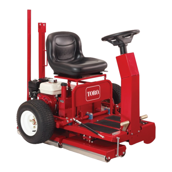
Toro GreensPro 1200 Installation Instructions
Roller mount kit
Hide thumbs
Also See for GreensPro 1200:
- Service manual (88 pages) ,
- Operator's manual (28 pages) ,
- Installation instructions (4 pages)
Advertisement
Quick Links
Roller Mount Kit
GreensPro
Model No. 131-1619
This product contains a chemical or chemicals known to the State of California to
Loose Parts
Use the chart below to verify that all parts have been shipped.
Description
No parts required
Roller support
Bolt (M10 x 35 mm)
Grommet
Bolt (M10 x 40 mm)
Locknut (M10)
Washer (M10)
Preparing the Machine
1. Remove the roller cylinders from the steering heads.
Note: Retain all of the hardware for later installation.
1. Bolt (spring)
2. Nut
3. Washer (spring)
4. Locknut
© 2014—The Toro® Company
8111 Lyndale Avenue South
Bloomington, MN 55420
™
1200 Greens Roller
Proposition 65 Warning
cause cancer, birth defects, or reproductive harm.
Figure 1
5. Roller cylinder
6. Washer (roller)
7. Split washer
8. Bolt (roller)
Register at www.Toro.com.
WARNING
CALIFORNIA
Qty.
–
Prepare the machine.
2
8
2
Install the kit.
8
16
16
2. Remove the bolts, the nuts, and the washers securing
the springs to each steering head.
3. Remove the steering heads from the machine as shown
in Figure 2.
Note: Retain the washers and the steering roller
assemblies. Discard the nuts and the bolts.
1. Washer (16)—retain
2. Nut (8)—discard
Form No. 3386-959 Rev A
Installation Instructions
Use
Figure 2
3. Steering heads
4. Bolt (8)—discard
Original Instructions (EN)
All Rights Reserved *3386-959* A
Printed in the UK
Advertisement

Related Manuals for Toro GreensPro 1200

Summary of Contents for Toro GreensPro 1200
- Page 1 3. Washer (spring) 7. Split washer 4. Locknut 8. Bolt (roller) 2. Nut (8)—discard 4. Bolt (8)—discard © 2014—The Toro® Company Register at www.Toro.com. Original Instructions (EN) All Rights Reserved *3386-959* A 8111 Lyndale Avenue South Printed in the UK...
- Page 2 4. Cut off the existing roller supports 2.5 to 5.7 cm (1 to 2-1/4 inches) from the frame (Figure 3). Important: Ensure that the existing supports do not obstruct the installation of the new supports. Figure 4 1. 20.4 cm (8.04 inches) 3.
- Page 3 7. Using the 8 bolts (M10 x 40 mm), 8 locknuts (M10), and the 8 previously removed washers, secure a new roller support to each of the previously removed roller bearings and smoothing rollers (Figure 6). Figure 8 Some parts not shown 1.
- Page 4 G025386 Figure 10 1. Joints 2. Short roller tube Figure 12 11. Connect each of the 2 springs to the appropriate 1. Straightedge 3. Rear roller assembly steering head, using the hardware previously removed; 2. Front roller assembly refer to Figure 11. Note: Keep part of the shank on each bolt exposed.