Table of Contents
Advertisement
Quick Links
This publication contains the installation, operation and
maintenance instructions for standard units of the CA, CF,
and CP Centrifugal Blowers.
• CA / CF SWSI
• CA-4 SWSI
• CPFD
• CAF-DW
• CPA / CPA-A / CPS / CPS-A / CPV
Carefully read this publication and any
supplemental documents prior to any
installation or maintenance procedure.
Loren Cook Company's catalogs CA/CF & CP provide
additional information describing the equipment, fan
performance, available accessories, and specification data.
For additional safety information, refer to AMCA
publication 410-96, Safety Practices for Users and Installers
of Industrial and Commercial Fans.
All of the publications listed above can be obtained from
Loren Cook Company by phoning (417)869-6474, extension
166; by FAX at (417)832-9431; or by e-mail at
info@lorencook.com.
For information on special equipment, contact Loren Cook
Company Customer Service Department at (417)869-6474.
Rotating Parts & Electrical Shock Hazard:
Disconnect electric power before working on unit.
Follow proper lockout / tagout procedures to ensure
the unit cannot be energized while being installed or
serviced.
A disconnect switch should be placed near the fan in
order that the power can be swiftly cut off, in case of
an emergency and in order that maintenance
personnel are provided complete control of the power
source.
Grounding is required. All field-installed wiring must
be completed by qualified personnel. All field-
installed wiring must comply with National Electric
Code (NFPA 70) and all applicable local codes.
Failure to follow these instructions could result in
death or serious injury.
Receiving and Inspection
Carefully inspect the fan and accessories for any damage
and shortage immediately upon receipt of the fan.
• Turn the wheel by hand to ensure it turns freely and
does not bind.
• Inspect dampers (if supplied) for free operation of all
moving parts.
• Record on the delivery receipt any visible sign of
damage.
INSTALLATION, OPERATION, AND MAINTENANCE MANUAL
• CA DWDI
• CA-4 DWDI
• CPFB
CA/CF/CP
Handling
Lift the fan by the base or lifting eyes. NOTICE! Never lift
by the shaft, motor, or housing.
Storage
If the fan is stored for any length of time prior to
installation, completely fill the bearings with grease or
moisture-inhibiting oil (refer to Lubricants on page 6).
Rotate the wheel several revolutions every three to five
days to keep a coating of grease on all internal bearing
parts.
Store the fan in its original crate and protect it from dust,
debris and the weather.
To maintain good working condition of the fan when it is
stored outdoors, follow the additional instructions below.
• Coat the shaft with grease or a rust preventative
compound.
• Wrap bearings for weather protection.
• Cover the inlet and outlet to prevent the accumulation of
dirt and moisture in the housing.
• Periodically rotate the wheel and operate dampers (if
supplied).
• Periodically inspect the unit to prevent damaging
conditions.
Installation
Motor Installation
Most motors are shipped mounted on the fans with belts
and drives installed. However, extremely heavy motors and
drives are shipped separately. These motors and drives will
require field installation.
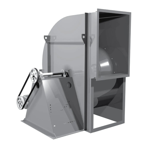
CA SWSI shown
Centrifugal Blowers
Advertisement
Table of Contents

Related Manuals for COOK CA SWSI

Summary of Contents for COOK CA SWSI
- Page 1 Store the fan in its original crate and protect it from dust, Loren Cook Company’s catalogs CA/CF & CP provide debris and the weather. additional information describing the equipment, fan performance, available accessories, and specification data.
- Page 2 7. place adjusting nut and locking nut on threaded rod near fan mounting bracket 8. alternately rotate adjusting nut at each mounting The attachment of roof mounted fans to the roof curb location until the fan weight is uniformly transferred to as well as the attachment of roof curbs to the building the isolators.
-
Page 3: Duct Installation
Duct Installation sealed with UL recognized fire caulk to both the curb cap duct adapter and the bottom of the fan. A minimum of two Efficient fan performance relies on the proper installation of inlet and discharge ducts. Be sure your fan conforms to separate outlines of caulk is recommended at the outer portion of the curb cap duct adapter. - Page 4 Wiring Installation rim of the pulley. 2. Slide the motor back until proper tension is reached. NOTICE! All wiring should be in accordance with For proper tension a deflection of approximately 1/4” local ordinances and the National Electrical per foot of center distance should be obtained by firmly Code, NFPA 70.
-
Page 5: Operation
Operation Start Up Turn the fan on. In variable speed units, set the fan to its Pre-Start Checks lowest speed and inspect for the following: 1. Lock out all the primary and secondary power • Direction of rotation. sources. • Excessive vibration. 2. -
Page 6: Maintenance
Class F insulation. Motors that are not supplied by Loren wheel. Cook Company should have the recommendation of the • Inspect springs and rubber isolators for deterioration motor manufacturer for use with a VFD. -
Page 7: Maximum Rpm
1257 1639 2065 1142 1490 1877 Should the motor prove defective within a one-year 1023 1334 1681 period, contact your local Loren Cook representative or 1225 1543 1108 1396 your nearest authorized electric motor service 1006 1268 representative. 1150 1035... -
Page 8: Bearing Replacement
Pulley and Belt Replacement After 24 hours of operation, retighten the setscrews to the appropriate torque. This assures full locking of the inner 1. Remove pulleys from their respective shafts. race to the shaft. Make sure the socket key or driver is in 2. -
Page 9: Troubleshooting
Overheated Motor: Troubleshooting • Motor improperly wired. Problem and Potential Cause • Incorrect direction of rotation. Make sure the fan rotates Low Capacity or Pressure: in same direction as the arrows on the motor or belt • Incorrect direction of rotation. Make sure the fan rotates drive assembly. - Page 10 Parts List CA,CF SWSI Arrangement 1 Drive Side View Discharge Side View Inlet Side View CA, CF SWSI Arrangement 3 Drive Side View Discharge Side View Inlet Side View CA, CF SWSI Arrangement 9 Drive Side View Discharge Side View Inlet Side View Part No.
- Page 11 CA, CF SWSI Arrangement 10 Drive Side View Discharge Side View Inlet Side View CA-4 SWSI, CF-4 SWSI Drive Side View Discharge Side View Inlet Side View CA,CF SWSI Arrangement 4 Drive Side View Discharge Side View Inlet Side View CA-4 S WSI, Part No.
- Page 12 CA DWDI Drive Side View Free Side View Discharge Side View CAF-DW Drive Side View Free Side View Discharge Side View CA-4 DWDI Drive Side View Free Side View Discharge Side View Part CA DWDI CAF-DW CA-4 DWDI Motor Slide Base Motor Motor Sheave Belt Set...
- Page 13 CPFB 10 15 Drive Side View Discharge Side View Inlet Side View CPA, CPA-A, CPS, CPS-A, CPV 10 15 16 17 Drive Side View Discharge Side View Inlet Side View CPA, CPA-A, CPS, CPS-A, CPV w/Optional Curb Cap and Inlet Box Accessory CPA, CPA-A, CPS, CPS-A, CPV Side View Inlet Side View...
- Page 14 CPFD Discharge Side View Inlet Side View CPA, CPA-A, CPS, CPS-A, CPV Arrangement 4 Inlet Side View Discharge Side View Drive Side View CPV-EC Inlet Side View Discharge Side View Drive Side View CPA, CPA-A, CPS, CPS-A, Part No. CPFD CPV Arr 4 &...
- Page 16 To make a warranty claim, notify Loren Cook Company, General Offices, 2015 East Dale Street, Springfield, Missouri 65803-4637, explaining in writing, in detail, your complaint and referring to the specific model and serial numbers of your fan. Upon receipt by Loren Cook Company of your written complaint, you will be notified, within thirty (30) days of our receipt of your complaint, in writing, as to the manner in which your claim will be handled.