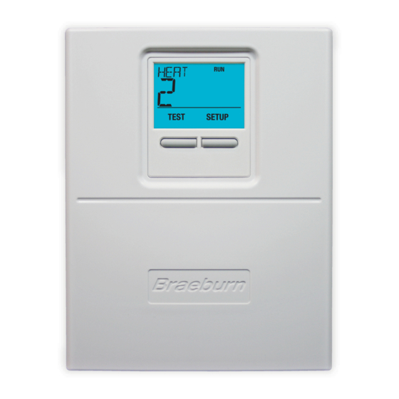
Braeburn Premier Series User Manual
Universal 7 day or 5-2 day programmable 2-heat/2-cool heat/cool digital thermostat
Hide thumbs
Also See for Premier Series:
- Installer's manual (20 pages) ,
- Installer manual (17 pages) ,
- Detailed installer manual (17 pages)
Table of Contents
Advertisement
Quick Links
MODEL
5100
USER MANUAL
Compatible with low voltage multi-stage
heat/cool systems with up to two stages of
heating and two stages of cooling.
READ ALL INSTRUCTIONS BEFORE PROCEEDING
Store this
booklet for
future reference
For more information on energy
savings, go to www.energystar.gov
© 2005 Braeburn Systems LLC All Rights Reserved.
YEAR
LIMITED
WARRANTY
Braeburn Systems LLC, as an Energy Star partner
has determined that this product meets the Energy
Star Guidelines developed by the U.S. Environmental
Protection Agency & the U.S. Department of Energy
for maximum energy efficiency.
Premier Series
Universal 7 Day or 5-2
Day Programmable
2-Heat/2-Cool Heat/Cool
Digital Thermostat
Pub. No. 5100-100-004
Advertisement
Table of Contents

Related Manuals for Braeburn Premier Series


Summary of Contents for Braeburn Premier Series
- Page 1 WARRANTY Store this booklet for future reference Braeburn Systems LLC, as an Energy Star partner has determined that this product meets the Energy Star Guidelines developed by the U.S. Environmental Protection Agency & the U.S. Department of Energy For more information on energy for maximum energy efficiency.
-
Page 2: Table Of Contents
CONTENTS FEATURES SPECIFICATIONS INSTALLATION Replacing Existing Thermostat Installing Your New Thermostat TESTING YOUR NEW THERMOSTAT PROGRAMMING Default Thermostat Settings Setting Current Time of Day and Day of Week Setting Thermostat User Options Setting Temperature Differentials 5.3.1 Setting Residual Cooling Fan Delay 5.3.2 Setting Extended Hold Time 5.3.3... -
Page 3: Features
FEATURES • Contemporary Styling with large display • 7 Day Programming Flexibility • AC Powered with Battery Back-up (2 AA Alkaline batteries included) • Preprogrammed for quick installation • Meets Title 24 and Energy Star (Energy Saving Guidelines) ® • Extended "HOLD" Mode •... -
Page 4: Installing Your New Thermostat
INSTALLATION cont. Illustration of round and rectangular mechanical thermostat exploded views. Installing Your New Thermostat NOTE: If you are installing this thermostat in a new installation be sure to locate the thermostat 4 to 5 feet above the floor in accordance with applicable building codes. Make sure to install the thermostat in a location that provides good airflow characteristics and avoid areas behind doors, near corners, air vents, direct sunlight or near any heat generating device. -
Page 5: Testing Your New Thermostat
INSTALLATION cont. Installing Your New Thermostat cont. 13. Turn the front thermostat body over exposing the rear view of the circuit board. 14. Locate the internal fan option switch, HG (Gas) / HE (Elec) on the circuit board. This switch controls the heating system fan delay. Select gas for gas or oil fired systems. This will allow the furnace to run for a few seconds before initiating the fan. -
Page 6: Programming
TESTING YOUR NEW THERMOSTAT cont. 5. Press the button on the keypad until the setpoint temperature is a minimum of 3 degrees lower than the current room temperature. 6. The cooling system should start within several seconds. Place the system switch in the OFF position. -
Page 7: Setting Thermostat User Options
PROGRAMMING cont. Setting Thermostat User Options The default user options are compatible with most systems and applications. They are normally set at the time of installation and usually do not require any modification under normal operating conditions. If you desire to change these settings, simply follow the instructions below. -
Page 8: Setting Filter Check Monitor
PROGRAMMING cont. Setting Residual Cooling Fan Feature cont. 5.3.2 5. Press the RETURN button again and the LCD display will show "FAN xx", where "xx" equals the fan delay time in seconds during the cooling mode of operation. 6. Press the button to set the residual cooling fan delay to your desired setting of 0 (disabled), 30, 60, or 90 seconds. -
Page 9: Setting Your Energy Saving Programs Tips Before Starting
PROGRAMMING cont. Setting Your Energy Saving Programs Tips Before Starting 5.4.1 • It is important for you to set the current time of day (note the AM/PM indicator in the display), and the current day of week correctly to avoid problems with program execution. This must be done prior to entering any programs. - Page 10 PROGRAMMING cont. Setting Your Energy Saving Programs cont. IMPORTANT NOTE! When in group selection, the thermostat will check if all of the days of that group have the same program setpoint times and temperatures. If so, the time and temperature of the individual setpoint (MORN, DAY, EVE, NIGHT) will be displayed.
-
Page 11: Entering Your 7 Day Program
PROGRAMMING cont. Setting Your Energy Saving Programs cont. Program Overview For Weekday/Weekend Programming Mode 5.4.4 (Programming switch set to 5-2 day—see installation section) Your thermostat contains separate Weekday and Weekend Program Groups that allow you to change the daily setpoint times and temperatures to meet your individual schedule needs. -
Page 12: Additional Operation Features
ADDITIONAL OPERATION FEATURES Review Set Temperature 1. Press and hold button. The current setpoint temperature will be displayed in the place of the current room temperature, and the indicator SET TEMP will be displayed. 2. The display will return to normal operating mode when the button are released. -
Page 13: Filter Check Monitor
ADDITIONAL OPERATION FEATURES cont. Filter Check Monitor The Filter Check Monitor displays a reminder for required filter replacement or cleaning, by flashing the FILT segment in the display. See instructions on your filter or heating/cooling unit for recommendations for interval setting. FILT When the selected interval has been reached, and required cleaning or replacement has been performed press the RETURN button in any normal mode to reset the timer and turn off the... -
Page 14: High Temperature Safety Switch
ADDITIONAL OPERATION FEATURES cont. High Temperature Safety Switch While the thermostat is in the HEAT mode of operation (selector switch in the HEAT position), the thermostat will mechanically turn-off if the room temperature raises higher than 99˚F (37˚ C). There is also a software feature that will automatically turn-off the thermostat in HEAT mode if the temperature raises higher than 93˚... -
Page 15: Low Battery Detection And Replacement
ADDITIONAL OPERATION FEATURES cont. Low Battery Detection and Replacement 6.11 This thermostat requires two (2) properly installed "AA" alkaline batteries to provide power for the thermostat to properly control the system operation. This thermostat is equipped with a low battery detection feature that constantly monitors the batteries during normal operating mode to determine whether they have sufficient power to provide proper operation. -
Page 16: Troubleshooting
TROUBLESHOOTING SYMPTOM POTENTIAL SOLUTION Thermostat does not Check to see if OFF is shown in display. This indicates that the system is turned off at the thermostat. Move the system selector turn on heating or switch to the HEAT or COOL position. After the compressor short cooling system. - Page 17 TROUBLESHOOTING cont. SYMPTOM POTENTIAL SOLUTION Low battery indicator Replace batteries immediately to maintain proper system operation. See Low Battery Detection and Replacement section is shown in of this manual. thermostat display. OFF is shown in This indicates that the system is turned off at the thermostat. Move the system selector switch to the HEAT or COOL position.
- Page 18 TROUBLESHOOTING cont. SYMPTOM POTENTIAL SOLUTION LO is shown in the The temperature sensed by the thermostat is lower than the 40˚ F (5˚ C) lower limit of the thermostats display range. The display thermostat display will return to normal after the sensed temperature rises within where the room the 40˚...
- Page 19 WIRING DIAGRAM Auxiliary Heat 1st Stage Fan Relay Relay Compressor (stage 2) Contact 2nd Stage 1st Stage Compressor Heat Relay Contactor Neutral 120 VAC 24 VAC Wiring Diagram for 2 Stage Heat, 2 Stage Cool Note: Eliminate connection to Y2 for units with single stage cooling.
- Page 20 Braeburn installation and operating instructions. Braeburn Systems LLC agrees to repair or replace at its option any Braeburn thermostat under warranty provided it is returned postage prepaid to our warranty facility in a padded carton within the warranty period, with proof of the original date of purchase and a brief description of the malfunction.