
Related Manuals for Samsung C109STR


Summary of Contents for Samsung C109STR
-
Page 1: Table Of Contents
MICROWAVE OVEN C109STR SERVICE Manual MICROWAVE OVEN CONTENTS 1. Precaution 2. Specifications 3. Operating Instructions 4. Disassembly and Reassembly 5. Alignment and Adjustments 6. Troubleshooting 7. Exploded Views and Parts List 8. PCB Diagrams 9. Schematic Diagrams... -
Page 2: Precaution
1-2 Special Servicing Precautions (Continued) 17. When checking the continuity of the witches or transformer, always make sure that the power is OFF, and one of the lead wires is disconnected. 18. Components that are critical for safety are indicated in the circuit diagram by shading, or . -
Page 3: Specifications
2. Specifications 2-1 Table of Specifications TIMER 99 MINUTES POWER SOURCE 230V 50Hz, AC POWER CONSUMPTION MICROWAVE : 1,400W GRILL : 1,300W CONVECTION : 1,700W OUTPUT POWER FROM 100 TO 900W(6 LEVEL POWER) (IEC-705 TEST PROCEDURE) OPERATING FREQUENCY 2,450MHz MAGNETRON OM75PH(31) COOLING METHOD COOLING FAN MOTOR... -
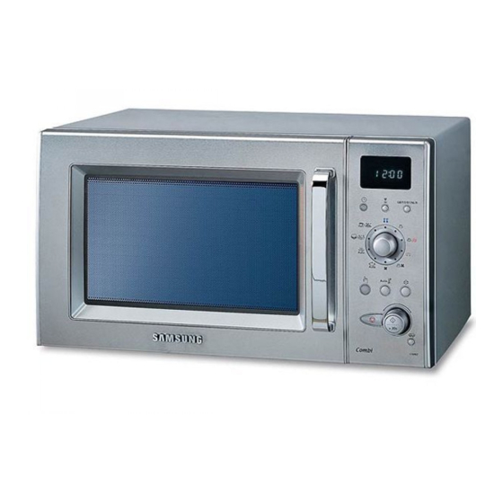
Page 4: Operating Instructions
3. Operating Instructions 3-1 Control Panel 3-2 Features & External Views Door Light Ventilation Holes Safety Interlock Holes Control Panel Guide Roller Glass Door Latches Coupler Grill Rack 216mm 369mm 517mm 511mm... -
Page 5: Disassembly And Reassembly
4. Disassembly and Reassembly 4-1 Replacement of Magnetron, Motor Assembly and Lamp Thermo S/W Cover Ai Remove the magnetron including the shield case, permanent magnet, choke coils and capacitors (all of which are contained in one assembly). 1. Disconnect all lead wires from the magnetron and lamp. - Page 6 4-3 Replacement of Door Assembly 4-3-4 Removal of Key Door &Spring 4-3-1 Removal of Door Assembly Remove pin hinge from Door "E" securing the upper hinge and lower hinge. Datach spring from Door "E" and key door. The remove door assembly. Upper Hinge Door "E"...
- Page 7 4-3-6 Reassembly Test After replacement of defective component parts of the door, reassemble it and follow the instructions below for proper installation and adjustment so as to prevent an excessive microwave leakage. 1. When mounting the door to the oven, be sure to adjust the door parallel to the bottom line of the oven face plate by moving the upper hinge and lower hinge in the direction necessary for proper alignment.
- Page 8 4-6 Replacement of Control Circuit Board 1. Be sure to disclyarge any static electricity from your body, and avoid touching the "touch control" circuitry. 2. Disconnect the connectors from the control circuit board. 3. Remove screws securing the control box assembly.
-
Page 9: Alignment And Adjustments
5. Alignment and Adjustments PRECAUTION 1. High voltage is present at the high voltage terminals during any cook cycle. 2. It is neither necessary nor advisable to attempt measurement of the high voltage. 3. Before touching any oven components or wiring, always unplug the oven from its power source and discharge the high voltage capacitor. - Page 10 5-4 High Voltage Capacitor 1. Check continuity of the capacitor with the meter set at the highest resistance scale. 2. Once the capacitor is charged, a normal capacitor shows continuity for a short time, and then indicates 9M . 3. A shorted capacitor will show continuous continuity. 4.
- Page 11 5-8 Output Power of Magnetron CAUTION MICROWAVE RADIATION PERSONNEL SHOULD NOT ALLOW EXPOSURE TO MICROWAVE RADIATION FROM MICROWAVE GENERATOR OR OTHER PARTS CONDUCTING MICROWAVE ENERGY. The output power of the magnetron can be measured by performing a water temperature rise test. Equipment needed : * Two 1-liter cylindrical borosilicate glass vessel (Outside diameter 190 mm) * One glass thermometer with mercury column...
- Page 12 5-9 Procedure for Measurement of Microwave Energy Leakage 1) Pour 275±15cc of 20±5° C(68±9° F) water in a beaker which is graduated to 600cc, and place the beaker in the center of the oven. 2) Start to operate the oven and measure the leakage by using a microwave energy survey meter.
-
Page 13: Troubleshooting
6. Troubleshooting PRECAUTION 1. CHECK GROUNDING BEFORE CHECKING FOR TROUBLE. 2. BE CAREFUL OF THE HIGH VOLTAGE CIRCUIT. 3. DISCHARGE THE HIGH VOLTAGE CAPACITOR. 4. WHEN CHECKING THE CONTINUITY OF THE SWITCHES OR TRANSFORMER, DISCONNECT ONE LEAD WIRE FROM THESE PARTS AND THEN CHECK CONTINUITY WITHOUT THE POWER SOURCE ON. - Page 14 6-1 Electrical Malfunction(continued) SYMPTOM CAUSE CORRECTIONS Oven lamp and fan motor turn on 1. Misadjustment or loose wiring Adjust door and latch switches. of primary latch switch 2. Defective primary latch switch Oven can program but timer 1. Open or loose wiring of does not start.
-
Page 15: Exploded Views And Parts List
7. Exploded Views and Parts List 7-1 Exploded Views MM42 MM73 MM52 MM21 MM67 MM01 MM62 MM66 MM61 MM63 MM60 MM69 MM58 MM72 MM07 MM59 MM65 MM87 MM68 MM17 MM71 MM55 MM05 MM57 MM03 MM35 MM06 MM18 MM17 MM56 MM10 MM19 MM16 MM20... - Page 16 7-2 Main Parts List - S.N.A : SERVICE NOT AVAILABLE Code No. Description Specification Q’ty Remark MB01 DE93-20020D ASSY BODY LATCH M959/XSA,-,-,-,- MB02 3405-000175 SWITCH-MICRO 250V,15A,200gf,SPST-NO MB03 3405-000178 SWITCH-MICRO 250V,15A,200gf,SPST-NO MB04 DE66-90054B LEVER-SWITCH NYLON#66(2021SW),40G,M959/X MB05 DE66-40021B LATCH-BODY -,-,-,M959/XSA,-,-,- MM01 DE64-00643A PANEL-OUTER C109ST,STS430#4,T0.5,W380.3, MM03...
- Page 17 7-3 Door Parts List MD08 MD06 MD04 MD09 MD12 MD24 MD07 MD10 MD01 Code No. Description Specification Q’ty Remark MD01 DE94-00743A ASSY DOOR C109ST,-,STS MD04 DE94-00075H ASSY DOOR-E(SEALANT) C100,SEALANT,3RD-1. MD06 DE64-40012C DOOR-C CK95,PBT,-,-,-,-,BLK,- MD07 DE61-00199A SPRING-KEY M1977,HSWR,D6,-,-,25 1/4,25 1 MD08 DE61-80002A HINGE-UPPER WHT,SHV-745CC1,SSEC,T2.3,26,...
- Page 18 MC01 ASSY CONTROL-BOX S.N.A MC07 RC-C139ST-01 ASSY PCB PARTS C109ST,230V50HZ MC09 DE64-00455A KNOB CK3D79ST,PC,-,-,-,-,-,-,- MC10 DE64-00456A KNOB-COVER CK3D79ST,PC,-,-,-,-,-,-,- MC13 DE94-00741G ASSY CONTROL-PANEL -,C109STR,-,STS,RUSSIA MC141 DE64-00450A BUTTON-SELECT(A) CK3D79ST,PC,-,-,SILVER, MC142 DE64-00451A BUTTON-SELECT(B) CK3D79ST,PC,-,-,SILVER, MC143 DE64-00452A BUTTON-SELECT(C) CK3D79ST,PC,-,-,SILVER, MC15 DE64-00453A BUTTON-START CK3D79ST,PC,-,-,SILVER,1.3 MC27...
- Page 19 7-5 Casing Parts List MA01 MA03 MA02 MA09 MA07 MA02 MA05 MA06 MA04 MA08 Code No. Description Specification Q’ty Remark MA01 DE31-10171A MOTOR-CONVECTION SMC-105EA,230V/50HZ,280 MA02 DE31-90019A BLADE-FAN SECC,T0.6,-,-,-,-,- MA02 DE31-90020A BLADE-FAN ALSTAR,T0.6,W250,L250,-,-,- MA03 DE47-70077A HEATER-CONVECTION SHC-118E1,-,-,1680W,-, MA04 DE60-40026B WASHER-PLAIN ID5.5,OD12,T1.0,SBC1,ZNC3,- MA05 DE62-90098B ADIABATIC-CASING...
- Page 20 7-6 Standard Parts List Code No. Description Specification Q’ty Remark DE60-10012A SCREW-TAP TITE -,SWR10,M4,L10,TH,+,-,3,ZPC2,- A-N-FILTER DE60-10012A SCREW-TAP TITE -,SWR10,M4,L10,TH,+,-,3,ZPC2,- A-P-CORD DE60-10012A SCREW-TAP TITE -,SWR10,M4,L10,TH,+,-,3,ZPC2,- B-PLATE DE60-10012A SCREW-TAP TITE -,SWR10,M4,L10,TH,+,-,3,ZPC2,- C-B-EARTH DE60-10018A SCREW-ASSY MACHINE -,WS,MSWR10,SN1,PH,M4X0.7P,-,8,-,- B-EARTH DE60-10034A SCREW-TH -,-,L10,STS304,TH,+,-,M4,-,- SENSOR DE60-10045A SCREW-TAP PH -,-,FEFZY,-,PH,M3,-,L6,-,- DE60-10052A...
- Page 21 8. P.C.B Diagrams 8-1 P.C.B Diagrams...
- Page 22 8-2 P.C.B Parts List Code No. Description Specification Q’ty Remark 3501-001062 RELAY-POWER 24VDC,523.2mW,16A,1FormA,15mS, 3501-001068 RELAY-POWER 24Vdc,523mW,16A,1FormA,15mS,10 RY6,RY7 3501-001155 RELAY-MINIATURE 24VDC,200MW,3000MA,1FORMA,10MS,10MS RY1,RY3,RY4,RY5,RY8 3601-001126 FUSE-CARTRIDGE 250V,1.6A,FAST-ACTING,CERAMIC,5x20mm FUSE1 DE07-10096A VF DISPLAY SVM-07MM09,GRN/ORG,7DIG,112seg, DSP1 DE09-00108A IC MICOM TMP87PM14F,OTP-32K,QFP,8BIT-64PIN,-,-,-,- DE34-00041A SWITCH-ENCODER 28VDC,10mA,ENDLESS,-,JES1424G ECD1 DE34-00063A SWITCH-PRESSURE DAIL,28VDC,10mA,24,-,JES1424GS ECD2 DE47-40024A...
-
Page 23: Schematic Diagrams
9. Schematic Diagrams 9-1 Schematic Diagrams MAGNETRON HIGH VOLTAGE DIODE TO CHASSIS HIGH VOLTAGE CAPACITOR H.V.FUSE SYMBOL COLOR BROWN BLACK BLUE HIGH VOLTAGE TRANSFORMER...