Cisco CRS-1 System Description
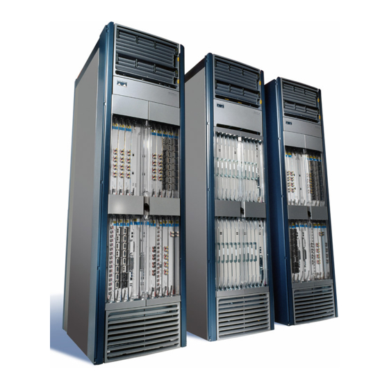
Carrier routing system 4-slot line card chassis
Hide thumbs
Also See for CRS-1:
- Administration manual (436 pages) ,
- Getting started manual (289 pages) ,
- Troubleshooting manual (264 pages)
Table of Contents
Advertisement
Quick Links
Advertisement
Table of Contents

Related Manuals for Cisco CRS-1


Summary of Contents for Cisco CRS-1
-
Page 1: System Description
Cisco CRS Carrier Routing System 4-Slot Line Card Chassis System Description April 2012 Americas Headquarters Cisco Systems, Inc. 170 West Tasman Drive San Jose, CA 95134-1706 http://www.cisco.com Tel: 408 526-4000 800 553-NETS (6387) Fax: 408 527-0883 Text Part Number: OL-10805-10... - Page 2 Modifications to this product not authorized by Cisco Systems, Inc. could void the FCC approval and negate your authority to operate the product. The Cisco implementation of TCP header compression is an adaptation of a program developed by the University of California, Berkeley (UCB) as part of UCB’s public domain version of the UNIX operating system.
-
Page 3: Table Of Contents
Obtaining Documentation, Obtaining Support, and Security Guidelines Cisco CRS 4-Slot Line Card Chassis Overview C H A P T E R System Overview Main Features of the Cisco CRS-1 Series 4-Slot Line Card Chassis Chassis Components Chassis Slot Numbers Chassis Cable Management... - Page 4 Contents Chassis Cooling System C H A P T E R Cooling System Overview Chassis Airflow Cooling System Operation Cooling System Redundancy Fan Tray Switch Fabric C H A P T E R Switch Fabric Overview Switch Fabric Operation Switch Fabric Cards Switch Fabric Card Description Switch Fabric Card Components Switch Fabric Card Physical Characteristics...
- Page 5 Initiate OIR Pushbutton Control and Management Ports Console and Aux Ports Service Ethernet Port USB Port Alarm Port Cisco CRS 4-Slot Line Card Chassis System Specifications A P P E N D I X Cisco CRS 4-Slot Line Card Chassis Specifications Environmental Specifications Compliance and Safety Reference N D E X...
- Page 6 Contents Cisco CRS Carrier Routing System 4-Slot Line Card Chassis System Description OL-10805-10...
-
Page 7: Preface
Preface This preface explains the objectives, intended audience, and organization of this Cisco CRS Carrier Routing System 4-Slot Line Card Chassis System Description, commonly referred to as the system description in this document, and presents the conventions that convey additional information. This preface includes the following sections: Objective, page v •... -
Page 8: Document Organization
Document Organization Document Organization This system description contains the following chapters and appendixes: Chapter 1, “Cisco CRS 4-Slot Line Card Chassis Overview,” • chassis. Chapter 2, “Chassis Power System,” • power system. Chapter 3, “Chassis Cooling System,” • Chapter 4, “Switch Fabric,” •... -
Page 9: Related Cisco Crs Documentation
Preface See Cisco CRS Carrier Routing System Regulatory Compliance and Safety Information for translations of warnings and information about the compliance and safety standards with which the Cisco CRS routing system conforms. Related Cisco CRS Documentation For a complete listing of Cisco CRS planning, installation, and configuration documents, see the following publications: •... -
Page 10: Obtaining Documentation, Obtaining Support, And Security Guidelines
Obtaining Documentation, Obtaining Support, and Security Guidelines Table 1 Changes to This Document Revision OL-10805-05 OL-10805-04 OL-10805-03 OL-10805-02 OL-10805-01 Obtaining Documentation, Obtaining Support, and Security Guidelines For information on obtaining documentation, obtaining support, providing documentation feedback, security guidelines, and also recommended aliases and general Cisco documents, see the monthly What’s New in Cisco Product Documentation, which also lists all new and revised Cisco technical documentation, at: http://www.cisco.com/en/US/docs/general/whatsnew/whatsnew.html... -
Page 11: Chapter 1 Cisco Crs 4-Slot Line Card Chassis Overview
This chapter describes the Cisco CRS Carrier Routing System 4-Slot Line Card Chassis and its main components. The following sections are included: System Overview, page 1-2 • Main Features of the Cisco CRS-1 Series 4-Slot Line Card Chassis, page 1-2 • Chassis Components, page 1-2 •... -
Page 12: Chapter 1 Cisco Cr 4-Slot Line Card Chassi Overview
Main Features of the Cisco CRS-1 Series 4-Slot Line Card Chassis The main features of the Cisco CRS-1 Series 4-slot line card chassis include: • A highly scalable router that provides a total routing capacity of 320 Gbps of bandwidth. - Page 13 Chapter 1 Cisco CRS 4-Slot Line Card Chassis Overview Up to four MSC, FP, or LSP line cards and four PLIMs. A line card and a PLIM are an associated • pair of cards that mate through the chassis midplane. The line card provides the forwarding engine for Layer 3 routing of user data, and the PLIM provides the physical interface and connectors for the user data.
- Page 14 Chassis Components Fan tray. The fan tray contains fans that push and pull air through the chassis. A removable air filter • is located above the power shelf in the front of the chassis. The front of the chassis contains the RPs, MSCs, FPs, LSPs, and PLIMs. This is where user data cables attach to the PLIMs and where cool air enters the chassis.
- Page 15 Chapter 1 Cisco CRS 4-Slot Line Card Chassis Overview Chassis Components Figure 1-2 Cisco CRS 4-Slot Line Card Chassis (Rear View) 1 Fan tray 2 Switch fabric card (half-height) slots Cisco CRS Carrier Routing System 4-Slot Line Card Chassis System Description OL-10805-10...
-
Page 16: Chassis Slot Numbers
Chassis Slot Numbers Chassis Slot Numbers This section describes the location and slot numbers for cards and modules that plug into the chassis. Figure 1-3 shows the slot numbers on the front side of the Cisco CRS 4-slot line card chassis. Figure 1-3 1 MSC slot 0 2 MSC slot 1... -
Page 17: Chassis Slot Numbers
Chapter 1 Cisco CRS 4-Slot Line Card Chassis Overview Figure 1-4 shows the slot numbers on the rear side of the Cisco CRS 4-slot line card chassis. Figure 1-4 1 Fan tray (FT0) 2 Switch fabric card slot (SM3) 3 Switch fabric card slot (SM2) OL-10805-10 4-Slot Line Card Chassis Rear View Slot Numbers (Switch Fabric Side) 4 Switch fabric card slot (SM1) -
Page 18: Chassis Cable Management
A router with a mix of 40G and 140G fabric cards is not a supported mode of operation. Such a mode is temporarily allowed only during the upgrade process. See Cisco CRS-1 Carrier Routing System to Cisco CRS-3 Carrier Routing System Upgrade Guide for a detailed procedure for upgrading a 40 Gbps CRS to a 140 Gbps CRS. - Page 19 Chapter 1 Cisco CRS 4-Slot Line Card Chassis Overview Table 1-1 CRS Compatibility Matrix Switch Fabric RP/DRP CRS-4-FC/S RP-A (CRS-4-RP), (40G) DRP-B (CRS-DRP-B) RP-A (CRS-4-RP), DRP-B (CRS-DRP-B) CRS-4-FC140/S RP-A (CRS-4-RP), (140G) DRP-B (CRS-DRP-B) RP-A (CRS-4-RP), DRP-B (CRS-DRP-B) (CRS-4-PRP-6G, CRS-4-PRP-12G) (CRS-4-PRP-6G, CRS-4-PRP-12G) PRP (CRS-4-PRP-6G, CRS-4-PRP-12G)
- Page 20 Chapter 1 Cisco CRS 4-Slot Line Card Chassis Overview CRS Hardware Compatibility Cisco CRS Carrier Routing System 4-Slot Line Card Chassis System Description 1-10 OL-10805-10...
-
Page 21: Chapter 2 Chassis Power System
Chassis Power System This chapter describes the Cisco CRS Carrier Routing System 4-Slot Line Card Chassis power system. The following sections are included: Power System Overview, page 2-1 • AC Power System, page 2-2 • DC Power System, page 2-7 •... -
Page 22: Ac Power Architecture
AC Power System AC Power Architecture The AC power system uses a single power shelf to provide reliable, 1:1 redundant power to all chassis components. AC power enters the rectifiers via the power shelf and is converted to DC. DC outputs from the supplies form 2 separate distribution buses. -
Page 23: Chapter 2 Chassi Power System
Chapter 2 Chassis Power System Figure 2-1 The AC power shelf physical dimensions are: Height—1.7 in. (4.3 cm) • Width—16.8 in. (42.6 cm) • Depth—16.2 in. (41.2 cm) • Weight—25 lb. (11.3 kg) with all AC rectifiers installed • Input AC power enters into each of the four AC rectifiers in the shelf. The AC rectifiers convert AC power into DC power, provide filtering, and then pass the DC power to either the A or B bus in the chassis midplane. -
Page 24: Ac Rectifier
AC Power System AC Rectifier The AC rectifier is an AC power supply that converts input AC power into the DC power necessary to power chassis components. The rectifier takes input AC power, rectifies the AC into DC, provides filtering and control circuitry, provides status signaling, and passes the DC power to either the A or B bus in the chassis midplane. -
Page 25: Ac Rectifier Indicators
Chapter 2 Chassis Power System AC Rectifier Indicators Each AC rectifier has power and status indicators. The AC rectifier shares auxiliary power with one another; therefore, the indicators are operational even when the AC rectifier is not powered from its input voltage. - Page 26 AC Power System Table 2-2 AC Rectifier LED Conditions Condition Thermal Alarm (5C before shutdown) Thermal Shutdown Defective Fan Blown AC Fuse in Unit No AC >15ms (single unit) AC present but not within limits AC not present Boost Stage Failure Over Voltage Latched Shutdown Over Current Noncatastrophic Internal Failure...
-
Page 27: Dc Power System
Chapter 2 Chassis Power System DC Power System This section provides an overview of the DC power system on the Cisco CRS 4-slot line card chassis. For a complete description of DC power on this routing system, see the Cisco CRS Carrier Routing System 4-Slot Line Card Chassis Installation Guide. -
Page 28: Dc Power Shelf Guidelines
The length of the wires depends on the router’s location. These wires are not available from Cisco Systems; they are available from any commercial vendor. DC power cables must be terminated by cable lugs at the power-shelf end. The lugs should be dual •... -
Page 29: Color Coding Of The Source Dc Power Cable
Chapter 2 Chassis Power System Color Coding of the Source DC Power Cable The color coding of the source DC power cable leads depends on the color coding of the site DC power source. Typically, green or green and yellow indicates that the cable is a ground cable. Because no color code standard exists for the source DC wiring, you must ensure that the power cables are connected to the DC-input power shelf terminal studs in the proper positive (+) polarity and negative (–) polarity. -
Page 30: Input-Power-Present Leds
DC Power System Figure 2-6 – (R TN ) (-4 8V /-6 0V ) 1 Power supply B1 wiring block 2 Power supply B0 wiring block 3 Coupling screw Input-Power-Present LEDs The DC power Input-Power-Present LEDs provide a visual indication to service personnel that there is voltage present across the input terminal’s connection (see the service person that there is power present. -
Page 31: Dc Power Wire Characteristics
Chapter 2 Chassis Power System DC Power Wire Characteristics For signal degradation to be averted, a conductor must be large enough to prevent its impedance from creating a voltage drop equal to 2 percent of the reference voltage. Also, the protective earth conductor must be large enough to carry all the current if the –48 VDC return fails. - Page 32 DC Power System Table 2-5 Resistance for Each Gauge of Copper Wire Wire Gauge 0000 Cisco CRS Carrier Routing System 4-Slot Line Card Chassis System Description 2-12 Ohms for each 1000 Feet of Wire 0.0489 0.0617 0.0778 0.098 0.1237 0.156 0.1967 0.248 0.3128...
-
Page 33: Chassis Cooling System
Chassis Cooling System This chapter describes the components that make up the cooling system of the line card chassis. The following sections are included: Cooling System Overview, page 3-1 • Chassis Airflow, page 3-2 – Cooling System Operation, page 3-3 –... -
Page 34: Chapter 3 Chassis Cooling System
Cooling System Overview Chassis Airflow Figure 3-1 shows how air moves through the line card chassis. The air inlet at the bottom front of the chassis pulls in ambient air and passes it through the card cage. Warm air is exhausted out the top rear of the chassis through the fans. -
Page 35: Cooling System Operation
Chapter 3 Chassis Cooling System The chassis has a replaceable air filter mounted in the front of the chassis in a slide-out tray above the power shelf. The chassis air filter is shown in You should change the air filter as often as necessary. In a dirty environment, or when you start getting frequent temperature alarms, check the intake grills for debris and check the air filter to see if it needs to be replaced. -
Page 36: Cooling System Redundancy
Cooling System Overview When there are no active alarms or failures, the fan control software checks temperature sensors every Note two to three minutes. Thermal Alarms Local thermal sensors (on individual cards) monitor temperatures and generate a thermal alarm when the cooling system is not cooling properly. -
Page 37: Fan Tray
Chapter 3 Chassis Cooling System Fan Tray Fan Tray Figure 3-3 shows a fan tray, which plugs into the rear of the chassis. Figure 3-3 Fan Tray H A N D L E T O B E U S E D O N LY F O R L IF T IN... -
Page 38: Fan Tray
Fan Tray The fan tray contains the following components: Four fans—Each fan uses –36 to –72 VDC as its input power. The fans operate in the range of 3500 • to 7500 RPM. The fan speed range limits listed in this document are nominal. These numbers have a tolerance Note of plus or minus 10 percent. - Page 39 Switch Fabric This chapter describes the Cisco CRS 4-slot line card chassis switch fabric and switch fabric card (SFC). The following sections are included: Switch Fabric Overview, page 4-1 • Switch Fabric Operation, page 4-2 • Switch Fabric Cards, page 4-3 •...
-
Page 40: Chapter 4 Switch Fabric
Switch Fabric Operation Ingress data packets are received at a physical interface on a PLIM and transferred to the associated MSC, where the packets are segmented into cells for efficient switching by the switch fabric hardware. Each MSC has multiple connections to each switch fabric plane, which it uses to distribute cells to each fabric plane. On egress, cells are reassembled into data packets before being transmitted by the egress MSC. -
Page 41: Switch Fabric Cards
Chapter 4 Switch Fabric At least two planes of the switch fabric (an even plane and an odd plane) must be active at all times for Note the Cisco CRS 4-slot line card chassis to operate. Otherwise, the switch fabric fails, causing a system failure. - Page 42 Chapter 4 Switch Fabric Switch Fabric Cards Figure 4-2 QQ123 Switch Fabric Card Cisco CRS Carrier Routing System 4-Slot Line Card Chassis System Description OL-10805-10...
- Page 43 Chapter 4 Switch Fabric Switch Fabric Cards Figure 4-3 QQ123-140G Switch Fabric Card Cisco CRS Carrier Routing System 4-Slot Line Card Chassis System Description OL-10805-10...
-
Page 44: Switch Fabric Card Components
Switch Fabric Cards Switch Fabric Card Components The switch fabric cards contain the following major components: S1 switch element—Implements Stage 1 of the switch fabric. Receives cells from the MSC (or RP) • and distributes them to Stage 2. • S2 switch element—Implements Stage 2 of the switch fabric. - Page 45 Chapter 4 Switch Fabric The physical characteristics of both the QQ123 and QQ123-140G switch fabric cards are: Height—2 in. (5.0 cm) • Depth—7.1 in. (18.0 cm) • Width— 12.1 in. (30.7 cm) • Weight—6 lb (2.7 kg) • Power consumption—up to 130 W •...
- Page 46 Chapter 4 Switch Fabric Switch Fabric Cards Cisco CRS Carrier Routing System 4-Slot Line Card Chassis System Description OL-10805-10...
-
Page 47: Chapter 5 Line Cards, Physical Layer Interface Modules, And Shared Port Adapters Overview
Line Cards, Physical Layer Interface Modules, and Shared Port Adapters Overview This chapter describes the modular services cards (MSCs), forwarding processor (FP), label switch processor (LSP), and associated physical layer interface modules (PLIMs). This chapter also describes the optional use of shared port adapters (SPAs). The cable-management system is also described. This chapter includes the following sections: •... - Page 48 Chapter 5 Line Cards, Physical Layer Interface Modules, and Shared Port Adapters Overview Line Cards and PLIMs Overview Line cards support several forwarding protocols, including IPV4, IPV6, and MPLS. Note that the route processor (RP) performs routing protocol functions and routing table distributions, while the line cards actually forwards the data packets.
-
Page 49: Plim Physical Interface Module On Ingress
Chapter 5 Line Cards, Physical Layer Interface Modules, and Shared Port Adapters Overview Figure 5-2 is a simple block diagram of the major components of an MSC/PLIM pair. These components are described in the sections that follow. This diagram also applies to the FP and LSP line cards. Figure 5-2 From fabric... -
Page 50: Msc To Fabric Section And Queuing
Line Cards and PLIMs Overview Maintains per-interface and per-protocol byte-and-packet statistics • Maintains Netflow accounting • Implements a flexible dual-bucket policing mechanism • MSC To Fabric Section and Queuing The “to fabric” section of the board takes packets from the ingress packet engine, segments them into fabric cells, and distributes (sprays) the cells into the four planes of the switch fabric. -
Page 51: Msc Cpu And Cpu Interface
Chapter 5 Line Cards, Physical Layer Interface Modules, and Shared Port Adapters Overview Back-pressure signalling for the queues • Dynamically shared buffer memory for each queue • A loopback function where transmitted data can be looped back to the receive side •... -
Page 52: Line Card Descriptions
Line Card Descriptions Line Card Descriptions Figure 5-3 shows a Cisco CRS routing system MSC. An MSC, FP, or LSP fits into any available MSC slot and connects directly to the midplane. All three versions of the MSC (CRS-MSC, CRS-MSC-B, and CRS-MSC-140G) are similar in appearance. - Page 53 Chapter 5 Line Cards, Physical Layer Interface Modules, and Shared Port Adapters Overview CRS_MSC-140G = 446 W – CRS- FP140 = 446 W – – CRS- LSP = 446 W Figure 5-4 shows the CRS-MSC front panel. Figure 5-4 CRS-MSC Front Panel 1 Status LED Figure 5-5 shows the CRS-MSC-B front panel.
- Page 54 Line Card Descriptions Figure 5-7 shows the CRS-FP40 front panel. Figure 5-7 CRS-FP40 Front Panel CRS-MSC-B 1 Status LED Figure 5-8 shows the CRS-FP140 front panel. Figure 5-8 CRS-FP140 Front Panel 1 Status LED Figure 5-9 shows the CRS-LSP front panel. Figure 5-9 CRS-LSP Front Panel 1 Status LED...
-
Page 55: Physical Layer Interface Modules
Chapter 5 Line Cards, Physical Layer Interface Modules, and Shared Port Adapters Overview Physical Layer Interface Modules A physical layer interface module (PLIM) provides the packet interfaces for the routing system. Optic modules on the PLIM contain ports to which fiber-optic cables are connected. User data is received and transmitted through the PLIM ports, and converted between the optical signals (used in the network) and the electrical signals (used by line card chassis components). - Page 56 Chapter 5 Line Cards, Physical Layer Interface Modules, and Shared Port Adapters Overview Physical Layer Interface Modules Figure 5-10 shows an example of a typical PLIM (in this case, a 14-port 10-GE XFP PLIM. Other PLIMs are similar. Figure 5-10 Typical PLIM —14-Port 10-GE XFP PLIM Cisco CRS Carrier Routing System 4-Slot Line Card Chassis System Description 5-10...
-
Page 57: Chassis Cable Management
Chapter 5 Line Cards, Physical Layer Interface Modules, and Shared Port Adapters Overview Chassis Cable Management The line card chassis has cable-management features for the front of the chassis. These cable-management features consist of horizontal cable-management trays above the card cage. These trays have a special telescoping feature that allows them to be extended when the chassis is upgraded with higher-density cards. - Page 58 Chapter 5 Line Cards, Physical Layer Interface Modules, and Shared Port Adapters Overview SPA Interface Processors and Shared Port Adapters Cisco CRS Carrier Routing System 4-Slot Line Card Chassis System Description 5-12 OL-10805-10...
-
Page 59: Chapter 6 Route Processor
Route Processor This chapter describes the route processor (RP) card. The following sections are included: Route Processor Overview, page 6-1 • Primary and Standby Arbitration, page 6-4 • • RP Card to Fabric Module Queuing, page 6-4 Route Processor Overview The route processor (RP) card is the system controller for the Cisco CRS 4-slot line card chassis. - Page 60 Chapter 6 Route Processor Route Processor Overview Figure 6-1 Route Processor Card Cisco CRS Carrier Routing System 4-Slot Line Card Chassis System Description OL-10805-10...
- Page 61 Chapter 6 Route Processor Details on the faceplate of the RP card are shown in Figure 6-2 1 Console port 2 AUX port 3 Alarm port 4 Error LED array 5 Management Ethernet port Table 6-1 RP Card Component Hard drive Memory PCMCIA Subsystems...
-
Page 62: Primary And Standby Arbitration
Primary and Standby Arbitration Primary and Standby Arbitration The two RP cards in a Cisco CRS 4-slot line card chassis operate in a primary-standby relationship. The routing system performs the following tasks to determine which RP is primary and which is standby: At chassis power-up, each RP boots its board components and runs self-tests. -
Page 63: Performance Route Processor
Chapter 6 Route Processor Figure 6-3 links connection Midplane Performance Route Processor The Performance Route Processor (PRP) is also available for the Cisco CRS 4-slot line card chassis. The PRP provides enhanced performance for both route processing and system controller functionality. Two PRP cards are required per chassis for a redundant system. - Page 64 Performance Route Processor Figure 6-4 The PRP has the following physical characteristics: • Height—20.6 in. (52.3 cm) • Depth—11.2 in. (28.5 cm) • Width—1.8 in. (4.6 cm) Weight—9.60 lb (4.35 kg) • Power consumption—175 W (with two SFP or SFP+ optics modules) •...
-
Page 65: Performance Route Processor Front Panel
Chapter 6 Route Processor Performance Route Processor Front Panel The PRP front panel includes: Two 1GE (SFP) or 10G (SFP+) ports for 1-GE or 10-GE uplinks • Service Ethernet RJ45 port • Console port • Auxiliary port • Push button switch to Initiate OIR process •... -
Page 66: Performance Route Processor Memory Options
Performance Route Processor A CPU interface and system control ASIC provides resources and communication paths between the CPU and the rest of the system to provide line card management, configuration, monitoring, protocol control, and exception packet handling. The fabric queuing portion of this ASIC acts as the fabric interface to handle the traffic to the fabric. -
Page 67: Initiate Oir Pushbutton
Chapter 6 Route Processor Initiate OIR Pushbutton The PRP front panel includes an OIR pushbutton (see item 1 in initiates the OIR process and avoids the loss of card information caused by a surprise extraction. If a card is extracted without initiating the OIR process (surprise extraction), the saving of logs or other important information is not possible. -
Page 68: Service Ethernet Port
Performance Route Processor Service Ethernet Port PRP functions include a Service Ethernet feature that enhances serviceability and troubleshooting of the system. The Service Ethernet RJ45 port provides a backdoor mechanism into the PRP if the main CPU subsystem is stuck and cannot be recovered. Through the Service Ethernet connection, you can perform the follow functions: Reset any cards in the chassis, including the local PRP •... -
Page 69: Appendix
Cisco CRS 4-Slot Line Card Chassis System Specifications This appendix provides the specifications for the Cisco CRS Carrier Routing System 4-Slot Line Card Chassis. It contains the following sections: • Cisco CRS 4-Slot Line Card Chassis Specifications, page A-1 Environmental Specifications, page A-3 •... -
Page 70: Cisco Crs 4-Slot Line Card Chassis Specifications
Cisco CRS 4-Slot Line Card Chassis Specifications Table A-1 Cisco CRS 4-Slot Line Card Chassis Specifications (continued) Cards and Modules Supported Power Shelves AC power shelf DC power shelf Maximum Power Consumption Maximum AC input power Maximum DC input power Power Redundancy AC Input Power Nominal input voltage... -
Page 71: Environmental Specifications
Appendix A Cisco CRS 4-Slot Line Card Chassis System Specifications Environmental Specifications Table A-2 lists the environmental specifications for the Cisco CRS 4-slot line card chassis. Table A-2 Cisco CRS 4-Slot Line Card Chassis Environmental Specifications Description Temperature Humidity Altitude Heat dissipation Power density Average air exhaust... - Page 72 Appendix A Cisco CRS 4-Slot Line Card Chassis System Specifications Compliance and Safety Reference Cisco CRS Carrier Routing System 4-Slot Line Card Chassis System Description OL-10805-10...
-
Page 73: I N D E X
acoustic noise specification, system AC power 2-2, 2-3 AC rectifiers components dimensions distribution power redundancy power shelf (figure) power shelves, AC 2-2, 2-4 AC rectifier description dimensions figure LEDs (table) 2-5, 2-6 power and status indicators status monitoring weight air filter airflow, chassis airflow, chassis (figure) alarm module... - Page 74 Index switch fabric card 4-3 to 4-7 temperature sensors Cisco CRS routing system switch fabric system specifications components of line card chassis cooling system architecture description inlet temperature sensors operation thermal sensors when cooling component fails See also fans and fan trays functions data egress (transmit), processing...
- Page 75 chassis slot numbers (front view) chassis slot numbers (MSC side) data flow through Cisco CRS DC power cable lug DC power shelf fan tray MSC block diagram PLIM block diagram Power Input Module (DC power) Route Processor card Route processor card front panel details switch fabric switch fabric card 4-4, 4-5...
- Page 76 Index description egress (transmit) data 5-2, 5-4 figure ingress (receive) data ingress (received) data operation overview SP (service processor) traffic shaping and queuing MSCs power consumption note, description of i-vi packet engine 5-3, 5-4 PCMCIA flash slots performance route processor (PRP) card figure wiring block PLIMs (physical layer interface modules)
- Page 77 overview PCMCIA flash slots primary and standby arbitration RP to fabric module queuing RP, See route processor (RP) card shared port adapters (SPAs) shock and vibration specifications, system slot numbers chassis front (PLIM side) chassis rear (MSC side) slot numbers, MSC side slot numbers, PLIM side SP (service processor) SPA interface processors (SIPs)
- Page 78 Index Cisco CRS Carrier Routing System 4-Slot Line Card Chassis System Description IN-6 OL-10805-10...