Table of Contents
Advertisement
Quick Links
Quick Start
Thank you for purchasing the MSI
MAG B365M MORTAR
motherboard. This Quick
®
Start section provides demonstration diagrams about how to install your computer.
Some of the installations also provide video demonstrations. Please link to the URL to
watch it with the web browser on your phone or tablet. You may have even link to the
URL by scanning the QR code.
Preparing Tools and Components
Intel
LGA 1151 CPU
®
CPU Fan
Chassis
DDR4 Memory
Power Supply Unit
Graphics Card
Thermal Paste
SATA Hard Disk Drive
SATA DVD Drive
A Package of Screws
Phillips Screwdriver
1
Quick Start
Downloaded from
ManualsNet.com
search engine
Advertisement
Table of Contents

Related Manuals for MSI MAG B365M MORTAR


Summary of Contents for MSI MAG B365M MORTAR
-
Page 1: Quick Start
Quick Start Thank you for purchasing the MSI MAG B365M MORTAR motherboard. This Quick ® Start section provides demonstration diagrams about how to install your computer. Some of the installations also provide video demonstrations. Please link to the URL to watch it with the web browser on your phone or tablet. -
Page 2: Safety Information
Safety Information y The components included in this package are prone to damage from electrostatic discharge (ESD). Please adhere to the following instructions to ensure successful computer assembly. y Ensure that all components are securely connected. Loose connections may cause the computer to not recognize a component or fail to start. -
Page 3: Installing A Processor
Installing a Processor https://youtu.be/4ce91YC3Oww Quick Start Downloaded from ManualsNet.com search engine... -
Page 4: Installing Ddr4 Memory
Installing DDR4 memory http://youtu.be/T03aDrJPyQs DIMMA1 DIMMA2 DIMMA2 DIMMA2 DIMMB2 DIMMB1 DIMMB2 Quick Start Downloaded from ManualsNet.com search engine... -
Page 5: Connecting The Front Panel Header
Connecting the Front Panel Header http://youtu.be/DPELIdVNZUI Power LED Power Switch JFP1 Reserved HDD LED Reset Switch HDD LED + Power LED + HDD LED - Power LED - Reset Switch Power Switch JFP1 Reset Switch Power Switch Reserved No Pin HDD LED - HDD LED HDD LED +... -
Page 6: Installing The Motherboard
Installing the Motherboard Quick Start Downloaded from ManualsNet.com search engine... -
Page 7: Connecting The Power Connectors
Connecting the Power Connectors http://youtu.be/gkDYyR_83I4 ATX_PWR1 CPU_PWR1 Quick Start Downloaded from ManualsNet.com search engine... -
Page 8: Installing Sata Drives
Installing SATA Drives http://youtu.be/RZsMpqxythc Quick Start Downloaded from ManualsNet.com search engine... -
Page 9: Installing A Graphics Card
Installing a Graphics Card http://youtu.be/mG0GZpr9w_A Quick Start Downloaded from ManualsNet.com search engine... -
Page 10: Connecting Peripheral Devices
Connecting Peripheral Devices Quick Start Downloaded from ManualsNet.com search engine... -
Page 11: Power On
Power On Quick Start Downloaded from ManualsNet.com search engine... -
Page 12: Table Of Contents
Contents Quick Start ......................1 Preparing Tools and Components ................1 Safety Information ....................2 Installing a Processor ..................... 3 Installing DDR4 memory ..................4 Connecting the Front Panel Header ............... 5 Installing the Motherboard ..................6 Connecting the Power Connectors ................. 7 Installing SATA Drives..................... - Page 13 JRAINBOW1: Addressable RGB LED connectors ..........35 Installing OS, Drivers & Utilities ................. 36 Installing Windows 10 ..................36 ® Installing Drivers ....................36 Installing Utilities ....................36 BIOS Setup ......................37 Entering BIOS Setup ..................... 37 Resetting BIOS ...................... 38 Updating BIOS .......................
-
Page 14: Specifications
* SATA1 port will be unavailable when installing SATA M.2 SSD in M.2 slot. ** Before using Intel Optane™ memory modules, please ensure that you have ® updated the drivers and BIOS to the latest version from MSI website. Intel B365 Chipset ®... - Page 15 Continued from previous page y 1x PS/2 mouse port y 1x PS/2 keyboard port y 2x USB 2.0 ports y 1x HDMI port Back Panel Connectors y 1x LAN (RJ45) port y 3x USB 3.1 Gen1 Type-A ports y 1x USB 3.1 Gen1 Type-C port y 3x audio jacks y 1x 24-pin ATX main power connector y 1x 8-pin ATX 12V power connector...
- Page 16 ACPI 6.1, SMBIOS 2.8 y Multi-language y Drivers y DRAGON CENTER y CPU-Z MSI GAMING Software y MSI App Player (BlueStacks) y Google Chrome™ ,Google Toolbar, Google Drive y Norton™ Internet Security Solution y GRAGON OPTIMIZATION y Hardware Monitor y Eyerest...
- Page 17 Continued from previous page y Protection ƒ PCIe Steel Armor ƒ Pre-install IO y Performance ƒ DDR4 Boost ƒ Core Boost ƒ USB with type A+C y Stability ƒ 7000+ Quality Test Special Features y VR ƒ VR Ready y Gamer Experience ƒ...
-
Page 18: Package Contents
Package contents Please check the contents of your motherboard package. It should contain: Motherboard MAG B365M MORTAR SATA 6Gb/s Cables Cable RGB LED Extension Cable 80cm 8.5H M.2 screws Case Badge Product Registration Card Application DVD Driver DVD User Manual... -
Page 19: Block Diagram
Block Diagram HDMI 2 Channel DDR4 Memory PCI Express Bus PCIe x1 slot PCIe x1 slot 1 x M.2 Switch 6 x SATA 6Gb/s B365 6 x USB 3.1 Gen1 6 x USB 2.0 LPC Bus NV6797 Realtek Super I/O ALC892 P/S2 Mouse / Keyboard Audio Jacks... -
Page 20: Rear I/O Panel
Rear I/O Panel PS/2 Mouse Line-In Line-Out Mic-In PS/2 Keyboard USB 3.1 Gen 1 Type-A USB 2.0 USB 3.1 Gen 1 Type-C LAN Port LED Status Table Link/ Activity LED Speed LED Status Description Status Description No link 10 Mbps connection Yellow Linked Green... -
Page 21: Realtek Audio Console
Realtek Audio Console After Realtek Audio Console is installed. You can use it to change sound settings to get better sound experience. Application Enhancement Device Selection Main Volume Connector Settings Jack Status y Device Selection - allows you to select a audio output source to change the related options. -
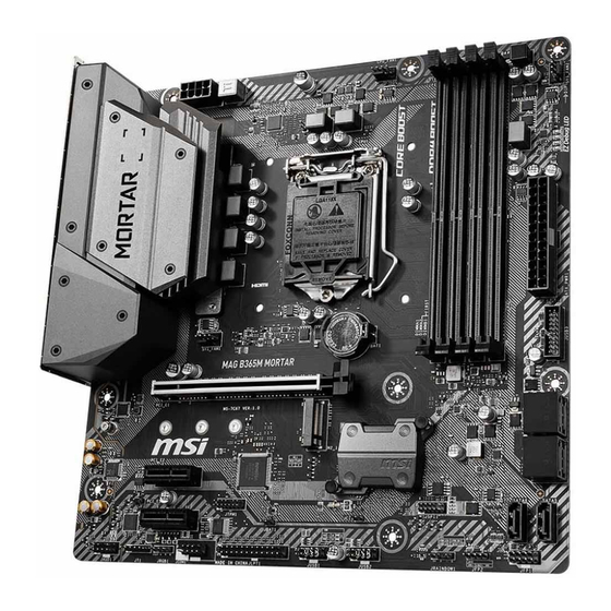
Page 22: Overview Of Components
Overview of Components CPU Socket CPU_FAN1 DIMMA1 DIMMA2 CPU_PWR1 DIMMB1 DIMMB2 SYS_FAN2 EZ Debug LEDs ATX_PWR1 SYS_FAN1 JUSB3 PCI_E1 M2_1 SATA▼1▲2 JTPM1 SATA▼3▲4 PCI_E2 SATA6 PCI_E3 SATA5 JFP1 JAUD1 JRGB1 JFP2 JCOM1 JRAINBOW1 JCI1 JBAT1 JUSB2 JLPT1 JUSB1 Overview of Components Downloaded from ManualsNet.com search engine... - Page 23 Component Contents Port Name Port Type Page CPU_FAN1, SYS_FAN1~2 Fan Connectors CPU_PWR1, ATX_PWR1 Power Connectors CPU Socket LGA 1151 socket DIMMA1/A2/B1/B2 DIMM Slots JAUD1 Front Audio Connector JBAT1 Clear CMOS Jumper JCI1 Chassis Intrusion Connector JCOM1 Serial Port Connector JFP1, JFP2 Front Panel Connectors JLPT1 Parallel Port Connector...
-
Page 24: Cpu Socket
Always unplug the power cord from the power outlet before installing or removing the CPU. Please retain the CPU protective cap after installing the processor. MSI will deal with Return Merchandise Authorization (RMA) requests if only the motherboard comes with the protective cap on the CPU socket. -
Page 25: Dimm Slots
DIMM Slots DIMMA1 DIMMB1 Channel A Channel B DIMMA2 DIMMB2 Memory module installation recommendation DIMMA1 DIMMA2 DIMMA2 DIMMA2 DIMMB1 DIMMB2 DIMMB2 Important Always insert memory modules in the DIMMA2 slot first. Due to chipset resource usage, the available capacity of memory will be a little less than the amount of installed. -
Page 26: Pci_E1~3: Pcie Expansion Slots
PCI_E3: PCIe 3.0 x1 (PCH lanes) Important If you install a large and heavy graphics card, you need to use a tool such as MSI Gaming Series Graphics Card Bolster to support its weight to prevent deformation of the slot. -
Page 27: Sata1~6: Sata 6Gb/S Connectors
SATA1~6: SATA 6Gb/s Connectors These connectors are SATA 6Gb/s interface ports. Each connector can connect to one SATA device. SATA2 SATA1 SATA4 SATA3 SATA6 SATA5 Important Please do not fold the SATA cable at a 90-degree angle. Data loss may result during transmission otherwise. -
Page 28: Cpu_Pwr1, Atx_Pwr1: Power Connectors
CPU_PWR1, ATX_PWR1: Power Connectors These connectors allow you to connect an ATX power supply. CPU_PWR1 Ground +12V Ground +12V Ground +12V Ground +12V +3.3V +3.3V +3.3V -12V Ground Ground PS-ON# Ground Ground Ground ATX_PWR1 Ground Ground PWR OK 5VSB +12V +12V +3.3V Ground... -
Page 29: Cpu_Fan1, Sys_Fan1~2: Fan Connectors
CPU_FAN1, SYS_FAN1~2: Fan Connectors Fan connectors can be classified as PWM (Pulse Width Modulation) Mode or DC Mode. PWM Mode fan connectors provide constant 12V output and adjust fan speed with speed control signal. DC Mode fan connectors control fan speed by changing voltage. You can follow the instruction below to adjust the fan connector to PWM or DC Mode. -
Page 30: Jusb3: Usb 3.1 Gen1 Connector
JUSB3: USB 3.1 Gen1 Connector This connector allows you to connect USB 3.1 Gen1 ports on the front panel. Power USB2.0+ USB3_RX_DN USB2.0- USB3_RX_DP Ground Ground USB3_TX_C_DP USB3_TX_C_DN USB3_TX_C_DN USB3_TX_C_DP Ground Ground USB3_RX_DP USB2.0- USB3_RX_DN USB2.0+ Power No Pin Important Note that the Power and Ground pins must be connected correctly to avoid possible damage. -
Page 31: Jaud1: Front Audio Connector
JAUD1: Front Audio Connector This connector allows you to connect audio jacks on the front panel. MIC L Ground MIC R Head Phone R MIC Detection SENSE_SEND No Pin Head Phone L Head Phone Detection JCOM1: Serial Port Connector This connector allows you to connect the optional serial port with bracket. SOUT Ground No Pin... -
Page 32: Jci1: Chassis Intrusion Connector
JCI1: Chassis Intrusion Connector This connector allows you to connect the chassis intrusion switch cable. Normal Trigger the chassis intrusion event (default) Using chassis intrusion detector 1. Connect the JCI1 connector to the chassis intrusion switch/ sensor on the chassis. 2. -
Page 33: Jbat1: Clear Cmos (Reset Bios) Jumper
JBAT1: Clear CMOS (Reset BIOS) Jumper There is CMOS memory onboard that is external powered from a battery located on the motherboard to save system configuration data. If you want to clear the system configuration, set the jumper to clear the CMOS memory. Keep Data Clear CMOS/ (default) -
Page 34: Jrgb1: Rgb Led Connector
(12V/G/R/B) with the maximum power rating of 3A (12V). Always turn off the power supply and unplug the power cord from the power outlet before installing or removing the RGB LED strip. Please use MSI’ s software to control the extended LED strip. Overview of Components Downloaded from ManualsNet.com... -
Page 35: Jrainbow1: Addressable Rgb Led Connectors
20% brightness, the connector supports up to 200 LEDs. Always turn off the power supply and unplug the power cord from the power outlet before installing or removing the LED strip. Please use MSI’ s software to control the extended LED strip. Overview of Components Downloaded from ManualsNet.com... -
Page 36: Installing Os, Drivers & Utilities
Installing OS, Drivers & Utilities Please download and update the latest utilities and drivers at www.msi.com ® Installing Windows 1. Power on the computer. ® 2. Insert the Windows 10 installation disc/USB into your computer. 3. Press the Restart button on the computer case. -
Page 37: Bios Setup
BIOS Setup The default settings offer the optimal performance for system stability in normal conditions. You should always keep the default settings to avoid possible system damage or failure booting unless you are familiar with BIOS. Important BIOS items are continuously update for better system performance. Therefore, the description may be slightly different from the latest BIOS and should be for reference only. -
Page 38: Resetting Bios
Updating BIOS Updating BIOS with M-FLASH Before updating: Please download the latest BIOS file that matches your motherboard model from MSI website. And then save the BIOS file into the USB flash drive. Updating BIOS: 1. Insert the USB flash drive that contains the update file into the USB port. -
Page 39: Ez Mode
EZ Mode At EZ mode, it provides the basic system information and allows you to configure the basic setting. To configure the advanced BIOS settings, please enter the Advanced Mode by pressing the Setup Mode switch or F7 function key. XMP switch Setup Mode switch Screenshot... - Page 40 y Information display - click on the CPU, Memory, Storage, Fan Info and Help buttons on left side to display related information. y Function buttons - enable or disable the LAN Option ROM, M.2/ Optane Genie, HD audio controller, AHCI, RAID, CPU Fan Fail Warning Control and BIOS Log Review by clicking on their respective button.
-
Page 41: Advanced Mode
Advanced Mode Press Setup Mode switch or F7 function key can switch between EZ Mode and Advanced Mode in BIOS setup. XMP switch Setup Mode switch Screenshot Search Language System information Boot device priority bar BIOS menu BIOS menu selection selection Menu display y BIOS menu selection - the following options are available:... -
Page 42: Settings
SETTINGS System Status f System Date Sets the system date. Use tab key to switch between date elements. The format is <day> <month> <date> <year>. <day> Day of the week, from Sun to Sat, determined by BIOS. Read-only. <month> The month from Jan. through Dec. <date>... - Page 43 fPEG X - Max Link Speed [Auto] Sets PCI Express protocol of PCIe x16 slots for matching different installed devices. [Auto] This item will be configured automatically by BIOS. [Gen1] Enables PCIe Gen1 support only. [Gen2] Enables PCIe Gen2 support only. [Gen3] Enables PCIe Gen3 support only.
- Page 44 fIpv4 PXE Support [Enabled] When Enabled, the system UEFI network stack will support Ipv4 protocol. This item will appear when Network Stack is enabled. [Enabled] Enables the Ipv4 PXE boot support. [Disabled] Disables the Ipv4 PXE boot support. fIpv6 PXE Support [Enabled] When Enabled, the system UEFI network stack will support Ipv6 protocol.
- Page 45 fIGD Multi-Monitor [Disabled] Enables or disables the multi-screen output from integrated graphics and external graphics card. This item appears when Initiate Graphic Adapter set to PEG. [Enabled] Enables multi-screen function for both integrated and external graphics cards. [Disabled] Disables this function. f USB Configuration Sets the onboard USB controller and device function.
- Page 46 Fast Boot [Disabled] MSI Fast Boot is the fastest way to boot the system. It will disable more devices to speed up system boot time which is faster than the boot time of Fast Boot.
- Page 47 fSecure Boot Support [Disabled] Enables or disables secure boot support. [Enabled] Enables the secure boot function and allow you to set the secure boot settings. [Disabled] Disables this function. fSecure Boot Mode [Standard] Selects the secure boot mode. This item is to select how the secure boot keys be loaded.
-
Page 48: Boot
fResume by USB Device [Disabled] Enables or disables the system wake up by USB devices. [Enabled] Enables the system to be awakened from sleep state when activity of USB device is detected. [Disabled] Disables this function. fResume From S3/S4/S5 by PS/2 Mouse [Disabled] Enables or disables the system wake up by PS/2 mouse. -
Page 49: Security
f Info Block effect [Unlock] Sets the state of Help information block. [Unlock] Sliding effect. [Lock] Fix the Help information block on the screen. f POST Beep [Disabled] Enables or disables the beep sound during system POST. f AUTO CLR_CMOS [Disabled] Enables or disables to resume the BIOS automatically when the system fail to boot up. -
Page 50: Save & Exit
Important When selecting the Administrator / User Password items, a password box will appear on the screen. Type the password then press <Enter>. The password typed now will replace any previous set password from CMOS memory. You will be prompted to confirm the password. - Page 51 Important Overclocking your PC manually is only recommended for advanced users. Overclocking is not guaranteed, and if done improperly, it could void your warranty or severely damage your hardware. f OC Explore Mode [Normal] Enables or disables to show the normal or expert version of OC settings. [Normal] Provides the regular OC settings in BIOS setup.
- Page 52 f CPU Ratio Offset When Running AVX [Auto] Sets a offset value to lower the CPU core ratio. It could be helpful for heat dissipation when running AVX instruction set. If set to Auto, BIOS will configure this setting automatically. This item appears when the installed CPU supports this function. f Ring Ratio [Auto] Sets the ring ratio.
- Page 53 f Memory Try It ! [Disabled] It improve memory compatibility or performance by choosing optimized memory preset. f DRAM Timing Mode [Link] Selects the memory timing mode. [Link] Allows user to configure the DRAM timing for all memory channel. [UnLink] Allows user to configure the DRAM timing for respective memory channel.
- Page 54 f MEMORY-Z Press Enter to enter the sub-menu. This sub-menu displays all the settings and timings of installed memory. You can also access this information menu at any time by pressing [F5]. fDIMMA1/A2/B1/B2 Memory SPD Press Enter to enter the sub-menu. The sub-menu displays the information of installed memory.
- Page 55 fAdjacent Cache Line Prefetch [Enabled] Enables or disables the CPU hardware prefetcher (MLC Spatial prefetcher). [Enabled] Enables adjacent cache line prefetching for reducing the cache latency time and tuning the performance to the specific application. [Disabled] Enables the requested cache line only. fCPU AES Instructions [Enabled] Enables or disables the CPU AES (Advanced Encryption Standard-New Instructions) support.
- Page 56 fCPU Current Limit (A) [Auto] Sets maximum current limit of CPU package in Turbo Boost mode. When the current is over the specified value, the CPU will automatically reduce the core frequency for reducing the current. fFCLK Frequency [Auto] Sets FCLK frequency. Lower FCLK frequency may help you to set higher base clock frequency.
-
Page 57: M-Flash
M-FLASH provides the way to update BIOS with a USB flash drive. Please down-load the latest BIOS file that matches your motherboard model from MSI website, save the BIOS file into your USB flash drive. And then follow the steps below to update BIOS. -
Page 58: Oc Profile
OC PROFILE f Overclocking Profile 1/ 2/ 3/ 4/ 5/ 6 Overclocking Profile 1/ 2/ 3/ 4/ 5/ 6 management. Press <Enter> to enter the sub- menu. fSet Name for Overclocking Profile 1/ 2/ 3/ 4/ 5/ 6 Name the current overclocking profile. fSave Overclocking Profile 1/ 2/ 3/ 4/ 5/ 6 Save the current overclocking profile. -
Page 59: Hardware Monitor
HARDWARE MONITOR Temperature & Speed Fan Manage Setting Buttons Temperature/ Voltage display f Temperature & Speed Shows the current CPU temperature, system temperature and fans' speeds. f Fan Manage ƒ PWM - allows you to select the PWM mode for fan operation. ƒ... -
Page 60: Intel ® Optane™ Memory Configuration
® ˜ Reboot to operating system. ˜ Insert the MSI Driver Disc into the optical drive. ˜ Click the Select to choose what happens with this disc pop-up notification, then select Run DVDSetup.exe to open the installer. If you turn off the AutoPlay feature from the Windows Control Panel, you can still manually execute the DVDSetup.exe from the root path of the MSI Driver Disc. - Page 61 5. Enable Intel Optane™ Memory. ® ˜ Run the Intel Rapid Storage Technology software. ® ˜ Click Intel Optane™ Memory tab and click Enable. ® ˜ Click Yes in the dialog. 6. Reboot System. WARNING Once you enable Intel Optane™ memory, in order to prevent seriously damage your ®...
-
Page 62: Removing The Intel ® Optane™ Memory
Removing the Intel Optane™ memory ® If you no longer want to use Intel Optane™ memory, you have to disable the Intel ® ® Optane™ memory before removing the Intel Optane™ memory module to avoid ® operating system damage. Please follow the steps below to remove the Intel Optane™... -
Page 63: Troubleshooting
Troubleshooting Before sending the motherboard for RMA Lost BIOS password repair, try to go over troubleshooting y Clear the CMOS, but that will cause guide first to see if your got similar you to lose all customized settings in the symptoms as mentioned below. -
Page 64: Regulatory Notices
이 기기는 가정용(B급) 전자파적합기기로서 주 y Visit the MSI website and locate a nearby distributor 로 가정에서 사용하는 것을 목적으로 하며, 모 for further recycling information. 든 지역에서 사용할 수 있습니다. - Page 65 Unión Europea al final de su periodo de vida. Usted their useful life. MSI will comply with the product take debe depositar estos productos en el punto limpio...
- Page 66 MSI si adeguerà a tale Direttiva ritirando tutti i prodotti marchiati MSI che sono stati venduti all’interno dell’Unione Europea alla fine del loro ciclo di vita.
- Page 67 Micro-Star Int’ l Co., Ltd. All other marks and names mentioned may be trademarks of their respective owners. No warranty as to accuracy or completeness is expressed or implied. MSI reserves the right to make changes to this document without prior notice. Technical Support...