
Related Manuals for Samsung CE2827NR


Summary of Contents for Samsung CE2827NR
-
Page 1: Table Of Contents
MICROWAVE OVEN CE2827NR SERVICE Manual MICROWAVE OVEN CONTENTS 1. Precaution 2. Specifications 3. Operating Instructions 4. Disassembly and Reassembly 5. Alignment and Adjustments 6. Troubleshooting 7. Exploded Views and Parts List 8. PCB Diagrams 9. Schematic Diagrams SRSC... - Page 2 PRECAUTIONS TO BE OBSERVED BEFORE AND DURING SERVICING TO AVOID POSSIBLE EXPOSURE TO EXCESSIVE MICROWAVE ENERGY (a) Do not operate or allow the oven to be (c) Before turning on microwave power operated with the door open. for any service test or inspection within (b) Make the following safety checks on the microwave generating all ovens to be serviced before activating...
-
Page 3: Precaution
1. Precaution Follow these special safety precautions. Although the microwave oven is completely safe during ordinary use, repair work can be extremely hazardous due to possible exposure to microwave radiation, as well as potentially lethal high voltages and currents. 1-1 Safety precautions ( 11. - Page 4 1-2 Special Servicing Precautions (Continued) 17. When checking the continuity of the witches or transformer, always make sure that the power is OFF, and one of the lead wires is disconnected. 18. Components that are critical for safety are indicated in the circuit diagram by shading, or .
-
Page 5: Specifications
2. Specifications 2-1 Table of Specifications TIMER 60 MINUTES POWER SOURCE 230V 50Hz, AC POWER CONSUMPTION MICROWAVE : 1,300W GRILL : 1100W COMBI : 2400W OUTPUT POWER FROM 100 TO 850W (IEC-705 TEST PROCEDURE) OPERATING FREQUENCY 2,450MHz MAGNETRON OM75P(31)ESS COOLING METHOD COOLING FAN MOTOR OUTSIDE DIMENSIONS 489(W) x 275(H) x 415(D) -
Page 6: Operating Instructions
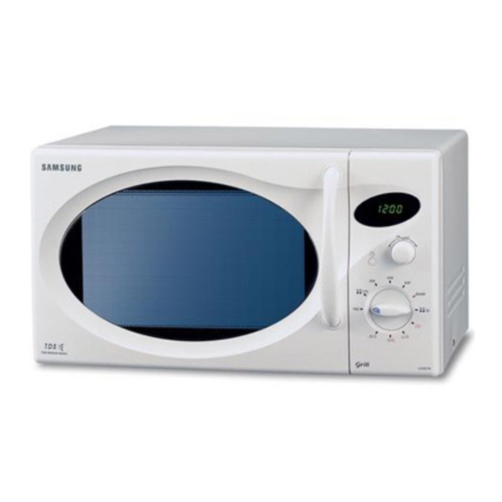
3. Operating Instructions 3-1 Control Panel 3-2 Features & External Views DOOR LATCHES VENTILATION HOLES GRILL LIGHT HANDLE METAL RACK TURNTABLE ROLLER RING SAFETY INTERLOCK HOLES DOOR COUPLER 342mm 206mm 489mm 397mm - 4 -... -
Page 7: Disassembly And Reassembly
4. Disassembly and Reassembly 4-1 Replacement of Magnetron, Motor Assembly and Lamp Remove the magnetron including the shield case, permanent magnet, choke coils and capacitors (all of which are contained in one assembly). 1. Disconnect all lead wires from the magnetron and lamp. 2. - Page 8 4-3 Replacement of Door Assembly 4-3-1 Removal of Door Assembly Remove hex bolts securing the upper hinge and lower hinge. Then remove the door assembly. Upper Hinge SCREWS SCREW Lower Hinge 4-3-2 Removal of Door "C" Insert flat screwdriver into the gap between Door "A"...
- Page 9 4-3-5 Reassembly Test After replacement of the defective component parts of the door, reassemble it and follow the instructions below for proper installation and adjustment so as to prevent an excessive microwave leakage. 1. When mounting the door to the oven, be sure to adjust the door parallel to the bottom line of the oven face plate by moving the upper hinge and lower hinge in the direction necessary for proper alignment.
- Page 10 4-6 Replacement of Control Circuit Board 4-6-1 Removal of Control Box Assembly 1. Be sure to ground any static electric charge in your body and never touch the control circuit. 2. Disconnect the connectors from the control circuit board. 3. Remove screws securing the control box assembly.
-
Page 11: Alignment And Adjustments
5. Alignment and Adjustments PRECAUTION 1. High voltage is present at the high voltage terminals during any cook cycle. 2. It is neither necessary nor advisable to attempt measurement of the high voltage. 3. Before touching any oven components or wiring, always unplug the oven from its power source and discharge the high voltage capacitor. - Page 12 5-4 High Voltage Capacitor 1. Check continuity of the capacitor with the meter set at the highest resistance scale. 2. Once the capacitor is charged, a normal capacitor shows continuity for a short time, and then indicates 9M. 3. A shorted capacitor will show continuous continuity. 4.
- Page 13 5-8 Output Power of Magnetron CAUTION MICROWAVE RADIATION PERSONNEL SHOULD NOT ALLOW EXPOSURE TO MICROWAVE RADIATION FROM MICROWAVE GENERATOR OR OTHER PARTS CONDUCTING MICROWAVE ENERGY. The output power of the magnetron can be measured by performing a water temperature rise test. Equipment needed : * Two 1-liter cylindrical borosilicate glass vessel (Outside diameter 190 mm) * One glass thermometer with mercury column...
- Page 14 5-10 Procedure for Measurement of Microwave Energy Leakage 1) Pour 275±15cc of 20±5° C(68±9° F) water in a beaker which is graduated to 600cc, and place the beaker in the center of the oven. 2) Start to operate the oven and measure the leakage by using a microwave energy survey meter.
-
Page 15: Troubleshooting
6. Troubleshooting PRECAUTION 1. CHECK GROUNDING BEFORE CHECKING FOR TROUBLE. 2. BE CAREFUL OF THE HIGH VOLTAGE CIRCUIT. 3. DISCHARGE THE HIGH VOLTAGE CAPACITOR. 4. WHEN CHECKING THE CONTINUITY OF THE SWITCHES OR TRANSFORMER, DISCONNECT ONE LEAD WIRE FROM THESE PARTS AND THEN CHECK CONTINUITY WITHOUT THE POWER SOURCE ON. - Page 16 6-1 Electrical Maltunction(continved) SYMPTOM CAUSE CORRECTIONS Oven lamp and fan motor turn on 1. Misadjustment or loose wiring Adjust door and latch switches. of primary latch switch 2. Defective primary latch switch Oven can program but timer 1. Open or loose wiring of Adjust door and interlock does not start.
-
Page 17: Exploded Views And Parts List
7. Exploded Views and Parts List 7-1 Exploded Views MM03 MD06 MD05 MD04 MM01 MD08 MM67 MM59 MD03 MM07 MD09 MD02 MM25 MM21 MM61 MM68 MM109 MM60 MD10 MM57 MM62 MD19 MM171 MM63 MD07 MM55 MD01 MD24 MM05 MM17 MD191 MM26 MD14 MC07... - Page 18 7-2 Main Parts List Code No. Description Specification Q'ty Remark MB01 DE96-00120B ASSY BODY LATCH M1717N,NC2000(HANDLE) MB02 3405-000175 SWITCH-MICRO 250V,15A,200gf,SPST-NO MB03 3405-000178 SWITCH-MICRO 250V,15A,200gf,SPST-NO MB041 DE66-00093A LEVER-SWITCH(A) NC2000,PP-TH53,-,-,-,-,NTR,HANDLE MB042 DE66-00094A LEVER-SWITCH(B) NC2000,PP-TH53,-,-,-,-,NTR,HANDLE MB05 DE72-00137A BODY-LATCH NC2000(0.6/0.8/1.2),PP,-,-,-,-,WHT,- MM01 DE70-00184P PANEL-OUTER MW850WA,C/STEEL,T0.5,-,P/WHT,NC2-0.8CU.FT MM03 DE39-00162B WIRE HARNESS-A...
- Page 19 7-3 Control & Door Parts List Code No. Description Specification Q'ty Remark MC01 ASSY CONTROL-BOX -,CE2827NR/BWT,P/WHT,-,CIS S.N.A MC03 DE72-00322A CONTROL-PANEL CE2827NR/BWT,ABS,-,-,-,-,P/WHT,- MC06 DE64-00095A WINDOW-DISPLAY SAN,-,M1727/M1927,- MC07 RC-EASY3R-05 ASSY PCB PARTS CE2727N,230V50Hz MC09 DE64-00097B KNOB-POWER CE2727/CE2927,ABS,-,-,-,-,-,-,POWER MC11 DE64-00096A KNOB-TIMER M1727/M1927,ABS,-,-,-,-,-,-,- MC13...
- Page 20 7-4 Standard Parts List Code No. Description Specification Q'ty Remark DE60-10012A SCREW-TAP TITE -,SWR10,M4,L10,TH,+,-,3,ZPC2,- N/FILTER DE60-10012A SCREW-TAP TITE -,SWR10,M4,L10,TH,+,-,3,ZPC2,- P-CORD DE60-10018A SCREW-ASSY MACHINE -,WS,MSWR10,SN1,PH,M4X0.7P,-,8,-,- BKT-HEATER DE60-10063A SCREW-TAP TH -,-,FEFN,-,TH,M4,-,L12,-,- P/OUTER DE60-10080B SCREW-WASHER -,2S,SWRCH18A,ZP2,PH,PI5,-,L10,-,- DE60-10080B SCREW-WASHER -,2S,SWRCH18A,ZP2,PH,PI5,-,L10,-,- DE60-10082H SCREW-A -,-,-,-,2S-4X12,TOOTHED,-,-,-,- B-LATCH DE60-10082H SCREW-A -,-,-,-,2S-4X12,TOOTHED,-,-,-,-...
- Page 21 8. P.C.B Diagrams 8-1 P.C.B Diagrams - 19 -...
- Page 22 8-2 P.C.B Parts List Code No. Description Specification Q'ty Remark 3501-001062 RELAY-POWER 24VDC,523.2mW,16A,1FormA,15mS, RY03 3501-001068 RELAY-POWER 24Vdc,523mW,16A,1FormA,15mS,10 RY04 3501-001155 RELAY-MINIATURE 24VDC,200MW,3000MA,1FORMA,10MS,10MS RY01,02 3601-001126 FUSE-CARTRIDGE 250V,1.6A,FAST-ACTING,CERAMIC,5x20mm FUSE1 DE07-00020A LED DISPLAY CSQ-4244G-21(L),30seg,5digit,45.2*22.3*27.9,- LED1 DE09-00208A IC MICOM S3C7054DG6-SOT4,SM-200111-AA,CE2727N,- IC01 DE26-00034A TRANS-L.V SLV-1933EN,230V,50Hz,7.0V/17V,-,35*11,PIN,- LVT1 DE30-20016A BUZZER CBE2220BA,STICK,-,-,-,-,-,-,-...
-
Page 23: Schematic Diagrams
9. Schematic Diagrams 9-1 Schematic Diagrams CONDITION OF OVEN DOOR IS OPENED 1.INPUT : 230V COOK OFF 2.DOOR : OPEN 3.LAMP : ON WIRING COLOR : P.C.B PATTERN : P.C.B IN/OUT POINT BRN : BROWN BLU : BLUE ORG : ORANGE WHT : WHITE YEL : YELLOW RED : RED...