GE Corometrics 250cx Series Service Manual
Hide thumbs
Also See for Corometrics 250cx Series:
- Service manual (202 pages) ,
- Operator's manual (250 pages)

Related Manuals for GE Corometrics 250cx Series


Summary of Contents for GE Corometrics 250cx Series
- Page 1 GE Healthcare Corometrics 250cx Series Monitor ™ Service Manual Corometrics 250cx Series Monitor English 2036947-001 Rev. C (paper) © 2007 General Electric Company. All Rights Reserved.
- Page 3 GE Healthcare ™ Corometrics 250cx Series Monitor Service Manual Corometrics 250cx Series Monitor English 2036947-001 Rev. C (paper) © 2007 General Electric Company. All Rights Reserved.
- Page 4 GE Medical Systems Information Technologies as repairable. Refer to the 250cx Series Service Manual for further information.
- Page 5 0086 Compliance A GE brand Corometrics 250cx Series Monitor bears CE mark CE-0086 indicating its conformity with the provisions of the Council Directive 93/42/EEC concerning medical devices and fulfills the essential requirements of Annex I of this directive. The device is manufactured in India; the CE mark is applied under the authority of Notified Body BSI (0086).
- Page 6 0086 CE- ii...
-
Page 7: Table Of Contents
Contents Introduction ........1-1 Revision History ........... . . 1-1 Safety Information . - Page 8 GE Healthcare Protocols ........
- Page 9 Communications Setup Screen ........3-21 Baudrate .
- Page 10 Front Panel Button Test ..........4-19 Connecting the Simulator .
- Page 11 Verification ............4-46 RS-232C Connector Loopback Test .
- Page 12 System Troubleshooting ..........5-37 General Troubleshooting .
- Page 13 Technical Specifications ......A-1 General Monitor ........... . . A-3 Operating Modes .
- Page 14 viii 250cx Series Maternal/Fetal Monitor Revision C 2036947-001...
-
Page 15: Introduction
Introduction Revision History Each page of this manual has a revision letter located at the bottom of the page. This letter identifies the revision level of the entire manual. This may be important if you have different manuals and you do not know which is the most current. For the initial release, all pages have the revision letter A. - Page 16 For your notes 250cx Series Maternal/Fetal Monitor Revision C 2036947-001...
-
Page 17: Safety Information
Caution, Important, and Note are used throughout the manual. In addition, standard equipment symbols are defined. Responsibility of the Manufacturer GE is responsible for the effects on safety, reliability, and performance if: assembly operations, extensions, readjustments, modifications, or repairs are carried out by persons authorized by GE;... -
Page 18: Hazard Definitions
Introduction: Safety Information Hazard Definitions Six types of special notices are used throughout this manual. They are: Danger, Warning, Caution, Contraindication, Important, and Note. The warnings and cautions in this Safety section relate to the equipment in general and apply to all aspects of the monitor. -
Page 19: Product Specific Hazards
In addition, proper placement of the paddles in relation to the electrodes is required to minimize harm to the patient. DEFIBRILLATION PROTECTION—When used with the GE Medical Systems Information Technologies-recommended accessories, the monitor is protected against the effects of defibrillator discharge. - Page 20 Introduction: Safety Information WARNINGS ELECTROSURGERY—The monitor is not designed for use with high-frequency surgical devices. In addition, measurements may be affected in the presence of strong electromagnetic sources such as electrosurgery equipment. EXPLOSION HAZARD—Do not use this equipment in the presence of flammable anesthetics or inside an oxygen tent.
- Page 21 ONLY remove cover plate if external display is used. TELEMETRY CONNECTIONS—Connect only to GE recommended telemetry system. Contact your GE service representative for more information. COLOR DISPLAY—Certain colors may have limited visibility at a distance. Color-blind individuals may experience this more often.
-
Page 22: Cautions
CAUTIONS ANNUAL SERVICING—For continued safety and performance of the monitor, verify the calibration, accuracy, and electrical safety of the monitor annually. Contact your GE Medical Systems Information Technologies Service Representative. DAILY TESTING—It is essential that the monitor and accessories be inspected every day. -
Page 23: Electromagnetic Interference
Turn equipment in the vicinity off and on to isolate the offending equipment. Reorient or relocate the other receiving device. Increase the separation between the interfering equipment and this equipment. If assistance is required, contact your GE Medical Systems Information Technologies Service Representative. Revision C... -
Page 24: Equipment Symbols
Introduction: Equipment Symbols Equipment Symbols The following is a list of symbols used on products manufactured by GE. Some symbols may not appear on your unit. Equipment Symbols ATTENTION: Consult accompanying documents. This symbol indicates that the waste of electrical... -
Page 25: Service Requirements
Technologies authorized service personnel only. Any unauthorized attempt to repair equipment under warranty voids that warranty. It is the user’s responsibility to report the need for service to GE Medical Systems Information Technologies or to one of GE’s authorized agents. -
Page 26: Intended Audience
Fetal Monitoring A Corometrics 250cx Series Monitor can be used for routine non-invasive and invasive fetal monitoring throughout labor and delivery (i.e., fetal heart rate and uterine activity monitoring). Fetal movement detection and Spectra Alerts are options that may be purchased. -
Page 27: Related Manuals
Introduction: Service Requirements Heart/Pulse Rate This parameter is intended for use in the non-invasive monitoring of the maternal heart/pulse rate (MHR/P). Related Manuals Manual Title 2020550-001 250cx Series Operator’s Manual 15457 Maternal/Fetal Monitoring, Clinical Application 2004435-001 Information For Prescribers Revision C 250cx Series Maternal/Fetal Monitor 1-13 2036947-001... - Page 28 Introduction: Service Requirements 1-14 250cx Series Maternal/Fetal Monitor Revision C 2036947-001...
-
Page 29: Equipment Overview
Equipment Overview Revision C 250cx Series Maternal/Fetal Monitor 2036947-001... - Page 30 For your notes 250cx Series Maternal/Fetal Monitor Revision C 2036947-001...
-
Page 31: Equipment Description
Equipment Overview: Equipment Description Equipment Description The 250cx Series Fetal Model monitors two Fetal Heart Rate channels plus Uterine Activity (TOCO or IUP). The 250cx Series Maternal/Fetal Model monitors maternal NIBP, SpO and MECG, in addition to the features found in the Fetal Model. A feature summary follows: Fetal Only Monitor Maternal/Fetal Monitor... -
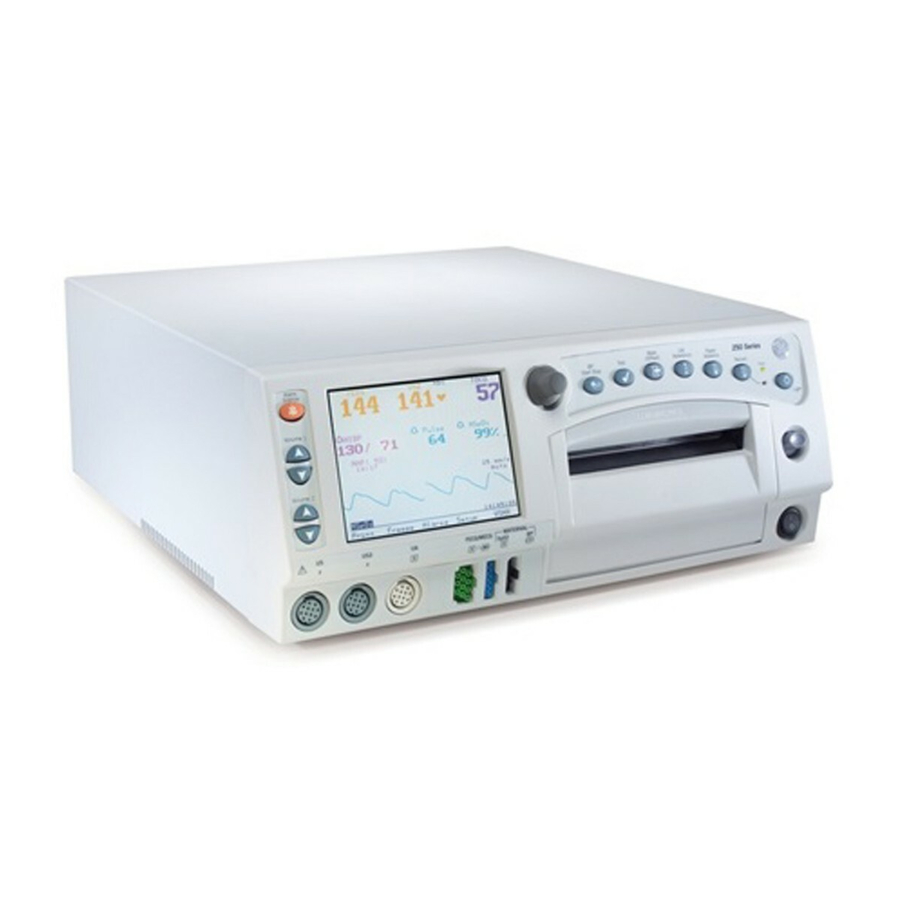
Page 32: Front Panel Description
Equipment Overview: Front Panel Description Front Panel Description FECG TOCO 165 172 NIBP MECG MSpO2 15:00 130/ 85 MAP (107) 03:15 25 mm/s II 2x FECG 03:22:45 Print Freeze Alarms Setup VSHX Monitor Front Table 1. Front Panel Name Description Display The monitor’s display is divided into several sections. - Page 33 Equipment Overview: Front Panel Description Table 1. Front Panel Name Description Mark [Offset] Button The Mark [Offset] button is a multi-function button. Mark: Pressing this button prints an event mark on strip chart paper (on the bottom two lines of the top grid). Offset: When the Heart Rate Offset mode is enabled, pressing and holding this button shifts the secondary FHR trend +20 bpm for visibility purposes.
- Page 34 Equipment Overview: Front Panel Description Table 1. Front Panel Name Description FHR2 Volume Decrease Button The four Volume buttons raise ( ) and lower ( ) the volume of sound emitted by the rear panel speaker. The upper pair controls the volume for FHR1. The lower pair FHR2 Volume Increase Button controls the volume for FHR2.
-
Page 35: Front Panel Displays
Equipment Overview: Front Panel Displays Front Panel Displays The monitor is divided into two main sections: patient information (the left-side of the monitor) and monitor functionality (the right-side of the monitor). The keys are ordered for user efficiency.The content and layout of the display can change, depending on which functions are installed in the monitor and the modes of operation in use. -
Page 36: Display Example
All alarms are enabled as indicated by Maternal/Fetal Monitor Display Example Setup Screens Review Chapters 3 and 4 of the Corometrics 250cx Series Operator’s Manual for information on the individual parameters and setup screens. Softkeys A softkey is an area on the screen that can be selected with the Trim Knob control. -
Page 37: Waveform Softkeys
Equipment Overview: Softkeys Waveform Softkeys The waveform title is a softkey used to select the waveform for display or to disable the area. The ECG Scaling and MECG lead labels are softkeys used to configure the waveform currently displayed. Dedicated Softkey Area Softkeys are located at the bottom of each screen. - Page 38 Equipment Overview: Softkeys TOCO 165 172 NIBP MECG MSpO 02:15 130/ 85 MAP (107) 03:15 25 mm/s II Auto 09:22:06 MECG 09:21:41 Frozen Print Freeze Alarms Setup VSHX Maternal/Fetal Monitor Display Summary Table 3. Display Summary Name Description Mode Title Softkeys Selects US, US2, FECG, NIBP, MHR/P, or MSpO Setup screens.
- Page 39 Equipment Overview: Softkeys TOCO 154 135 Vital Signs History Date: 24-Mar 24-Mar 24-Mar 24-Mar 24-Mar Time: 12:00 12:10 12:20 12:30 12:40 NIBP MSpO2 MECG HX Interval: 10 min Print PrintAll View Exit l Maternal Vital Signs History Screen Softkeys Table 4. Maternal Vital Signs History Screen Softkeys Name Description Print Softkey...
-
Page 40: Rear Panel Description
J102 J103 DEVICE TO SALE BY OR ON THE ORDER OF 0086 A PHYSICIAN. J101 J104 GE Medical Systems European Representative Munzinger Straße 3-5; D-79111 Freiburg Germany 100 -120V ~ 50-60HZ 100W J110 J109 J111 U.S. PATS. 3,982,528 4,533,926 4,573,479... - Page 41 Name Description J112 External VGA Connector Connector for external VGA display. Use of recommended GE external display will allow monitor front panel display video to be replicated remotely. Speaker The rear panel speaker emits an audible tone for heart rates,...
-
Page 42: Optional Components
Adding Spectra Alerts The monitor can be upgraded to include Spectra Alerts. Refer to Appendix D of the Corometrics 250cx Series Operator’s Manual for more information. Adding Fetal Movement Detection The monitor may be upgraded to include Fetal Movement Detection. Contact your GE Service Representative for further information. -
Page 43: Nellcor Puritan Bennett Model N-400 Fetal Pulse Oximeter
Equipment Overview: Peripheral Components Using interface cable, connect one end to an available RS-232C port (J109 or J111 only) on the 250cx Series Monitor; connect the other end to the Serial port on the pulse oximeter. Communications Access the Communications Setup service mode screen and set the mode to Nellcor for the appropriate port. -
Page 44: Dinamap Models Pro Series 100-400 And Procare
Equipment Overview: DINAMAP® Models PRO Series 100-400 and ProCare DINAMAP Models PRO Series 100-400 and ProCare ® All of the above DINAMAP Monitors can be interfaced to a 250cx Series Monitor to provide a printout of NIBP values on the strip chart paper. ILC-1926 An ILC-1926 is required to interface with the DINAMAP PRO Series and ProCare Monitors. -
Page 45: Ge Healthcare Protocols
® Exergen TAT-5000™ 4800 only) GE Healthcare Protocols 250Plus Protocol The 250Plus protocol provides clinical information to a central station. The protocol includes all current clinical parameters and is provisioned for additional data or parameters as they become available. The 250Plus protocol is closely related to the 1371 Notes protocol. The 250Plus protocol operates in one of two modes: Compatibility or Extended. -
Page 46: Theory Of Operation
Equipment Overview: Theory of Operation Theory of Operation Systems Overview The 250cx Series system is made up of front-end and back-end PWAs, system power supply, and recorder module. The main PWA forms the heart of the monitor control functions. This PWA along with the Communications PWA form the back end of the monitor. - Page 47 Equipment Overview: Theory of Operation Revision C 250cx Series Maternal/Fetal Monitor 2-19 2036947-001...
- Page 48 Equipment Overview: Theory of Operation Digital System Processor (DSP) Display PWA The DSP Display PWA consists of two independent functioning modules: the DSP and the Display interface. The DSP processes analog and digital data from the front- end modules and interfaces to the main processor. The ECG and ultrasound analog information is processed and heart rates are output to the main board via a shared memory.
- Page 49 Equipment Overview: Theory of Operation Revision C 250cx Series Maternal/Fetal Monitor 2-21 2036947-001...
- Page 50 Equipment Overview: Theory of Operation Main Board PWA The Main Board makes up the central processing unit for the 250cx Series Fetal Monitor. The Main Board accepts simultaneously processed parameters directly from four separate modules. The minimum configuration monitor has only the DSP board as an input module.
- Page 51 Equipment Overview: Theory of Operation the internal SpO cable that in turn connects to the SpO Carrier PWA. The MSpO connector PWA keeps the sensitive analog SpO signals shielded on the inner layers of the board. R1 and R2 are 0 Ohm resistors that are used to provide a means of disconnecting the shorts between pins 4 and 9 and pins 8 and 11 if needed.
- Page 52 Equipment Overview: Theory of Operation digitized and sent over the barrier via an opto coupler where it is routed similarly to the FECG analog signal. The uterine pressure front-end processes the pressure signals from the external TOCO or IUP sensor (uses same inputs) by amplifying and filtering the inputs and converts the signals via serial analog to digital converter.
- Page 53 Equipment Overview: Theory of Operation FECG signals as well as the MECG mode lines. The MECG analog signals are routed separately from the front panel to the MECG daughter PWA. The MSpO input signals enter the SpO carrier PWA directly. Video Decoder PWA The decoder PWA interfaces between the DSP/Display PWA and the LCD panel.
- Page 54 Equipment Overview: Theory of Operation 2-26 250cx Series Maternal/Fetal Monitor Revision C 2036947-001...
-
Page 55: Installation
Installation 250cx Series Maternal/Fetal Monitor Revision C 2036947-001... - Page 56 For your notes 250cx Series Maternal/Fetal Monitor Revision C 2036947-001...
-
Page 57: Tools Required
Installation: Tools Required Tools Required Refer to “Preventative Maintenance Inspection Report” on page 4-55 for a list of required tools. Connections Fetal Acoustic Stimulator This connector is provided for connection to a Corometrics Model 146 Fetal Acoustic Stimulator. Remote Marks Connector This connector is provided for connection to an optional Corometrics Remote Event Marker. -
Page 58: J101 Connector (Model 340 Telemetry System Interface)
Installation: Connections J101 Connector (Model 340 Telemetry System Interface) NOTE: For additional information, This connector is for future interfacing to the receiver of a Corometrics Model 340 refer to the Model 340 Service Manual, Telemetry System. P/N 2006920-001. A telemetry indicator is displayed beneath the FHR1 mode field: you connect a telemetry receiver to the 250cx Series Monitor;... -
Page 59: J109, J110, And J111 Connectors (Rs-232C)
DINAMAP ProCare Monitors Quantitative Sentinel/Perinatal System (any RS-232C connector) When shipped from the GE factory, all three ports are configured as follows: Communications Setup = Nellcor baudrate (bps) = 2400 At the above settings, connectors J109 and J111 are ready for connection to an NPB Model N-200. -
Page 60: Power
Connect the detachable line cord to the rear panel power connector; plug the other end into a hospital grade grounded wall outlet of appropriate voltage. (If you are unsure about the voltage, contact your hospital Biomedical Engineering Department or GE Service Representative.) 250cx Series Maternal/Fetal Monitor Revision C... -
Page 61: J112 (External Display Connector)
J112 (External Display Connector) This 15-pin sub-D connector is designed for interfacing to an external video display. Only connect external displays approved by GE Medical Systems Information Technologies. Self-Test Routine The 250cx Series Monitor contains a self-test routine which checks the calibration and internal circuitry of the monitor. -
Page 62: Battery-Backed Ram Status
AC power. Information on setting the time and date is found in the General Setup screen section in Chapter 4 of the Corometrics 250cx Series Monitor Operator’s Manual. 250cx Series Maternal/Fetal Monitor... -
Page 63: Setup
(re-alarm time). The re-alarm time is adjustable from the password-protected Install Options Screen 2. For further information, refer to Chapter 11, “Alarms” in the Corometrics 250cx Series Operator’s Manual. The monitor also alerts you when paper is running low and when the recorder is completely out of paper. - Page 64 Installation: Setup Press down on the latch on the right side of the strip chart recorder door. Fan the pack of Z-fold paper on all sides to loosen any folds and to ensure proper feed of the paper through the recorder. Hold the package of paper so that: the black squares are on the bottom of the pack;...
- Page 65 Installation: Setup paper is compatible with and required for the 250cx Series. Unfold two sheets from the top of the package so that they extend toward you. Place the pack in the drawer so that the pack is laying flat in the recorder. Slowly close the strip chart recorder door, being careful not to skew the paper.
-
Page 66: Mounting A Strain Gauge
Installation: Service Mode Screens Mounting a Strain Gauge To mount a strain gauge post, refer to the manufacturer’s directions. Setup Screens The 250cx Series Monitor provides a variety of options that are all selected using setup screens shown on the display. All functions are performed easily using the front panel Trim Knob. -
Page 67: Service Lock Screen
Installation: Service Mode Screens Service Lock Screen The “Service Lock Screen” on page 3-13, is used to access the remaining service screens. It displays the following information: Keypad Version MSpO For Nellcor: Nellcor 506 or NELL-3 Version and Date For Masimo: DSP: Version, MCU: Version, PID: Version For Ohmeda Oximetry: Version NIBP Version CPU Version... -
Page 68: Install Options Screens
Installation: Service Mode Screens Install Options Screens Install Options Screen 1 Language: English Line Frequency: 60 Hz Scaling: 30-240 Recorder Font Size: Large VS Print Interval: Real Time Paper Chime: Low/Out Paper Volume: HBC: HR Offset: FM Remote Mark: Scale: Auto PrintAll COMM... - Page 69 Installation: Service Mode Screens Language This field is used to set the language shown on the display and printed on the strip chart recorder paper. Use the Trim Knob control to cycle through the available options: English, Spanish, French, German, Dutch, Swedish, Italian, Danish, Finnish, and Norwegian. (The monitor is factory set for the country in which it is being used.) Line Frequency This field is used to define the line power frequency for the country in which the...
- Page 70 Installation: Service Mode Screens Paper Volume This field sets the volume of the paper chime. As you adjust the volume, a sample tone sounds. You can choose from a range of 1 to 9 (1 = lowest, 9 = loudest). HBC (Heartbeat Coincidence) The heartbeat coincidence feature alerts you when there is the possibility that you may be monitoring a duplicate signal.
- Page 71 Installation: Service Mode Screens FM Remote Mark This field configures the marker annotation that is printed on the strip chart paper whenever a patient presses the button on the Remote Marker accessory. Use the Trim Knob control to alternate between On and Off. The factory default setting is Off. annotation is commonly used to record an “event”;...
- Page 72 Installation: Service Mode Screens FECG Artifact Elimination This field is used to enable/disable FECG Artifact Elimination which affects only the direct FECG mode. Use the Trim Knob to alternate between On and Off. (The factory default setting is Off.) When On is selected, any new heart rate value which differs by more than ±25 bpm from the previously calculated heart rate is not printed on the strip chart paper.
- Page 73 Installation: Service Mode Screens NIBP 1 min Interval This field is used to enable/disable the 1 minute interval selection on the maternal BP Setup screen. Use the Trim Knob control to alternate between On and Off. (The factory default setting is Off.) NIBP Display Setting this field to a value reduces the chance of error.
-
Page 74: Printing System Setup Information
Installation: Printing System Setup Information Store Current To Hospital Select this option if you wish to store your current monitor settings as your hospital’s preferred default settings. When you select this option, the Default Settings: softkey reflects the change (i.e., Default Settings: change to Hospital). Printing System Setup Information Use the Trim Knob to select the PrintAll softkey on the bottom of Install Options Screen 1 to see an overall summary of the monitor’s setup screens. -
Page 75: Communications Setup Screen
Installation: Communications Setup Screen Communications Setup Screen The Communications Setup screen, allows you to configure the unit’s J109, J110, and J111 RS-232C Serial Interface ports for connecting to optional peripheral equipment. Each port is configured for baudrate and mode. To use the Communications Setup screen: Select the Service softkey from the General Setup screen. -
Page 76: Configuration Switches
Installation: Configuration Switches Configuration Switches The switches configure the operational characteristics of the 250cx. Switch Name Setting Factory Test Off = Enabled J102 Levels Off = HP, On = Coro RESERVED Set to Off NIBP Option Off = Enabled 5:Off 6:Off = Nellcor 5:Off 6:On = Ohmeda MSpO Option... -
Page 77: Factory Defaults
Installation: Factory Defaults Factory Defaults Table 1. Summary of Factory Defaults Setup Field Description Factory Default Default Options Hospital Preference Screen FECG or FHR Volume US/US2 FHR Alarm Limits High Low 200-140, Off 160 120 bpm 60-140, Off Audio Alarms On, Off Volume NIBP... - Page 78 Installation: Factory Defaults Table 1. Summary of Factory Defaults Setup Field Description Factory Default Default Options Hospital Preference Screen MSpO Response Time Fast Normal, Fast (Nellcor 506) Response Time Fast Fast (Nellcor NELL-3) Averaging Time (Masimo) 8 seconds 2, 4, 8, 10, 12, 14, 16 seconds Sensitivity (Masimo) Normal Normal, Maximum...
- Page 79 Installation: Factory Defaults Table 1. Summary of Factory Defaults Setup Field Description Factory Default Default Options Hospital Preference Screen General Play Song Off, Happy Birthday, Brahms’ Setup Lullaby, Rock-a-Bye-Baby, All Song Volume Brightness 0-9 (nine = brightest) Paper Speed United States: 3 cm/min 1-3 cm/min International: 1 cm/min Date...
- Page 80 Installation: Factory Defaults Table 1. Summary of Factory Defaults Setup Field Description Factory Default Default Options Hospital Preference Screen Install Language Set according to shipping Set according to shipping Options destination destination Screen 1 Line Frequency United States: 60 Hz 50 Hz, 60 Hz (Service) International: 50 Hz...
-
Page 81: Maintenance
Maintenance Revision C 250cx Series Maternal/Fetal Monitor 2036947-001... - Page 82 For your notes 250cx Series Maternal/Fetal Monitor Revision C 2036947-001...
-
Page 83: Maintenance Schedule
Maintenance: Maintenance Schedule Maintenance Schedule Self-Test Maintenance Item Maintenance Action Maintenance Frequency Frequency TOCO as needed U/S Transducers as needed MECG Cables as needed Main Board Battery as needed Monitor Exterior as needed Monitor vacuum interior Before each monitoring session Printhead as needed Main Board power supply voltages... -
Page 84: Visual Inspection
Maintenance: Maintenance Schedule Self-Test Maintenance Item Maintenance Action Maintenance Frequency Frequency MSpO Measure voltage as needed breakdown Measure voltage as needed breakdown Measure voltage as needed breakdown Mains to Chassis using DC voltage for 1 min. hi-pot voltage tester as needed 2.121 kVdc Display Check Verify DSP board... -
Page 85: Cleaning
Maintenance: Cleaning Cleaning General care and cleaning are required for the 250cx Series Monitor and its accessories. If an accessory is not listed, consult the manufacturer’s instructions. CAUTION Unplug the monitor from the AC power source and detach all accessories from the monitor. Do not immerse accessories in any liquid. -
Page 86: Display
Maintenance: Cleaning Display To clean the display screen, use a soft, clean cloth dampened with a glass cleaner. Do not spray the glass cleaner directly onto the display. Do not use alcohol or hospital disinfectants like Cidex* or Betadine. Tocotransducer and Ultrasound Transducer CAUTIONS ABRASION—Do not use abrasive cloth, sharp objects, or abrasive cleaners. -
Page 87: Maternal Nibp Cuffs And Hoses
Maintenance: Cleaning Dampen a cloth or paper towel with one of the following products; then wring out until only slightly wet: Sodium Hypochlorite 5.25% (Bleach) diluted 10:1 Cidex* Sporicidin* Soap and water Rub soiled area until clean. Dry with a soft, dry cloth. Maternal NIBP Cuffs and Hoses General The cuff must be thoroughly cleaned with the specified detergent before reuse. -
Page 88: Periodic Thermal Printhead Cleaning
Allow 2 hours for drying. The user has the responsibility to validate any deviations from the recommended method of cleaning and disinfection. For additional information on infection control procedures, contact GE Medical Systems Information Technologies Technical Support. Sensors Adhesive sensors are sterile and for single use only. Reusable sensors should be cleaned before reuse with a 70% alcohol solution. -
Page 89: Disposal Of Product Waste
Maintenance: Disposal of Product Waste After cleaning, rinse the transducer thoroughly in distilled water and replace the dome loosely. Dry the transducer with sterile gauze. CAUTIONS AUTOCLAVE—Do not autoclave pressure transducer. IMMERSION—Do not immerse any part of the electrical connector of the transducer in the cleaning solution at any time. Examine the outer sheath of the cable for perforations. -
Page 90: Packaging Material
If you have questions concerning disposal of the product, please contact GE Medical Systems Information Technologies or its representatives. Electrical Safety Tests Refer to the “Preventative Maintenance Inspection Report” on page 4-55 for required tools to perform all electrical safety tests in this section. -
Page 91: Chassis Leakage
Maintenance: Electrical Safety Tests Connect the leakage tester’s external lead to the equipotential lug on the rear of the monitor. Verify and record the results in Electrical Safety section of the Preventative Maintenance Report. Chassis Leakage With the leakage tester connected to power, connect the monitor’s power cord to the leakage tester and turn monitor power on. -
Page 92: Patient-To-Ground Leakage For Iup
Maintenance: Electrical Safety Tests Patient-to-Ground Leakage for IUP/Toco With the leakage tester connected to power, connect the monitor’s power cord to the leakage tester. Connect the transducer to the monitor. Wrap the transducer in aluminum foil or immerse in normal saline solution. Select the leakage tester’s settings to measure Lead-to-Ground leakage current for all leads as appropriate. -
Page 93: Patient-To-Line (Iso) Leakage For Us1/Us2
Maintenance: Electrical Safety Tests Patient-to-Line (ISO) Leakage for US1/US2 With the leakage tester connected to power, connect the monitor’s power cord to the leakage tester. Connect the transducer to the monitor. Wrap the transducer in aluminum foil or immerse in normal saline solution. Select the leakage tester’s settings to measure Lead-to-Line leakage current for all leads as appropriate. -
Page 94: Dielectric (Hi-Pot) Tests
Maintenance: Electrical Safety Tests Dielectric (Hi-Pot) Tests CAUTION POWER OFF—Turn off the monitor prior to performing any of the hi-pot tests. Patient–to–AC-Line Using DC Voltage for 1 Minute Connect the monitor to the hi-pot tester as shown on in the figure below. NOTE: The hi-pot tester voltage is 5.656 kVdc. - Page 95 OR ON THE ORDER OF 0086 A PHYSICIAN. J101 J104 GE Medical Systems Information Technologies, Inc 8200 West Tower Avenue; Milwaukee, WI, USA European Representative GE Medical Systems Information Technolgies GmbH Munzinger Stra e 3-5; D-79111 Freiburg Germany 100 -120V ~ 50-60HZ 100W...
-
Page 96: Checkout
OR ON THE ORDER OF 0086 A PHYSICIAN. J101 J104 GE Medical Systems Information Technologies, Inc 8200 West Tower Avenue; Milwaukee, WI, USA European Representative GE Medical Systems Information Technolgies GmbH Munzinger Stra e 3-5; D-79111 Freiburg Germany 100 -120V ~ 50-60HZ 100W J110 U.S. -
Page 97: Equipment Required
Maintenance: Self-Test Routine affect the overall system performance. Therefore, between factory service visits it is necessary that the proper operation of each monitor be verified by performing the functional checkout procedure described in this section. This procedure should be completed prior to initially placing the monitor on a patient, when monitor performance needs to be verified, on a semi-annual basis, or more frequently as dictated by your equipment maintenance and management policies. - Page 98 Maintenance: Self-Test Routine in the FHR2 area, with both mode titles displaying Test. The monitor adds 50 mmHg to the present pressure input level and displays this value in the UA display area; the mode title displays Test. If MECG is the selected waveform, a simulated waveform appears on the display.
-
Page 99: Front Panel Button Test
Maintenance: Front Panel Button Test Front Panel Button Test This procedure ensures the functionality of the front panel buttons. Apply power to the 250cx Series Monitor. Disconnect all transducers from the front panel. Depress the monitor’s Record button and verify the following: The yellow indicator next to the button illuminates continuously. -
Page 100: Mecg Test
Maintenance: MECG Test Insert the green plug of the FECG/MECG adapter cable, cat. no. (REF) 1442AAO, into the monitor’s FECG/MECG connector. Connect the sub-cables of the other end of the simulator interconnect cable into the color-coded connectors on the monitor/adapter: ECG, US, and UA. Turn on the Model 325 Simulator. - Page 101 Maintenance: MECG Test Table 2. MECG Test Simulator Settings Section Switch Setting Rate/CMR RATE Rate MANUAL FECG/MECG Mode MECG QRS Amplitude 500 µV QRS Polarity GENERAL Pattern Memory Main Mode TOCO 10. Repeat Step 9 for each of the following rates: 30, 120, 210, and 240 bpm. 11.
- Page 102 Maintenance: MECG Test strip chart paper after approximately 30 seconds. 14. Set the simulator’s ECG Mode switch to the Off position. MECG Ramp MECG Oscillation 4-22 250cx Series Maternal/Fetal Monitor Revision C 2036947-001...
-
Page 103: Fecg Test
Maintenance: FECG Test FECG Test This portion of the functional checkout procedure ensures the integrity of the FECG circuitry and the heart rate channel of the recorder. Connect the simulator’s ECG cable to the FECG connector on the monitor’s “Y” adapter cable. - Page 104 Maintenance: FECG Test Table 3. FECG Test Simulator Settings Section Switch Setting Rate/CMR RATE Rate MANUAL FECG/MECG Mode FECG QRS Amplitude 15 µV QRS Polarity GENERAL Pattern Memory Main Mode TOCO Repeat Step 7 for each of the following rates: 30, 60, 210, and 240 bpm. Change the simulator’s QRS Polarity switch from + to –.
- Page 105 Maintenance: FECG Test The recorder prints an oscillation of 15 bpm between 110 and 125 bpm on the top grid of the strip chart paper. (Refer to figure “FECG Artifact Elimination” on page 4-26.) Δ 16. Repeat Step 15 for the rate value of 22.
-
Page 106: Ultrasound Test
Maintenance: Ultrasound Test FECG Artifact Elimination Ultrasound Test This portion of the functional checkout procedure ensures the integrity of the ultrasound circuitry and the heart rate channel of the recorder. Connect the simulator’s US cable to the US connector on the monitor. Set the switches on the Model 325 Input Simulator according to Table 4. - Page 107 Maintenance: Ultrasound Test The strip chart recorder immediately reflects this new input rate. Use the simulator’s Manual Adjustment knob to decrease the heart rate value by more than 13 bpm from the 120 bpm baseline. Verify the following on the monitor: The FHR1 value immediately reflects this new input rate.
-
Page 108: Fetal Movement Detection Test
Maintenance: Fetal Movement Detection Test Ultrasound Ramp Fetal Movement Detection Test This portion of the functional checkout procedure ensures the integrity of the fetal movement detection circuitry and the heart rate channel of the recorder. (Refer to figure “Fetal Movement Detection” on page 4-29.) Connect the simulator’s US cable to the US connector on the monitor. -
Page 109: Ultrasound Transducer Test
Maintenance: Ultrasound Transducer Test Table 5. Fetal Movement Detection Test Simulator Settings Section Switch Setting Mode US/FMD Signal Level Ultrasound/FMD Rate MANUAL Main Mode TOCO Fetal Movement Detection Ultrasound Transducer Test Inspect an ultrasound transducer as follows: Ensure there are no cracks around the transducer face. Visibly inspect the condition of the cable, strain relief, and connector pins. -
Page 110: Uterine Activity Test
Maintenance: Uterine Activity Test The recorder prints the message US on the center margin of the strip chart paper after approximately 20 seconds. Gently rub each crystal of the ultrasound transducer rhythmically. (There are nine crystals. Eight are arranged around the circumference of the transducer; one is in the center.) Verify the following: Good sensitivity is apparent. - Page 111 Maintenance: Uterine Activity Test displayed accordingly and that the recorder prints a continuous line at the corresponding value on the uterine activity channel of the strip chart paper. Place the simulator’s UA Level switch at each of the level settings: 0, 10, 50, and 100 relative units.
-
Page 112: Testing The Tocotransducers
Maintenance: Testing the Tocotransducers Uterine Activity Ramp Testing the Tocotransducers CAUTIONS LEAKAGE TEST—Perform a leakage and dielectric test on the tocotransducer per applicable standards. FUNCTIONAL TEST—Perform a functional response test on the tocotransducer. Inspect a Nautilus Tocotransducer as follows: Check for any cracks or contaminants on the tocotransducer especially on the diaphragm located on the bottom of the tocotransducer. -
Page 113: Strain Gauge Transducer Test
Maintenance: Strain Gauge Transducer Test The UA value shows the default setting. The UA mode shows TOCO. The recorder prints the messages UA REF and TOCO on the strip chart paper. Apply gentle pressure to the tocotransducer diaphragm and verify that the UA value responds to the pressure input. -
Page 114: Pattern Memory Test
Maintenance: Pattern Memory Test Apply gentle pressure on the strain gauge diaphragm and verify that the display and recorder respond to the input. Increasing force should produce an increasing value and vice versa. Disconnect the strain gauge from the front panel of the monitor. Verify the following on the monitor: The UA value and mode are both blank. -
Page 115: Dual Heart Rate Test (Non-Pattern)
Maintenance: Dual Heart Rate Test (Non-Pattern) Connect the appropriate simulator sub-cables to the corresponding connectors on the monitor. Enable the modes on the simulator. Set the simulator’s Pattern Memory switch to the ON position. If not already on, depress the monitor’s Record button. Verify the following on the monitor: Each heart rate area (FHR1, FHR2, and/or MECG) responds accordingly for value, mode, and heartbeat indicator. -
Page 116: Dual Ultrasound Modes
Maintenance: Dual Heart Rate Test (Non-Pattern) Rate, FECG and US” on page 4-36.) Table 7. Dual Heart Rate Test (Non-Pattern) Simulator Settings Section Switch Setting Rate/CMR RATE Rate 120 bpm FECG/MECG Mode FECG QRS Amplitude 50 µV QRS Polarity Mode ULTRASOUND/FMD Level Rate... -
Page 117: Alarm Test
Maintenance: Alarm Test Model 325 Simulator and one ultrasound transducer. This procedure details using two transducers since it is more practical for a test site. If not already on, depress the monitor’s Record button. Plug one ultrasound transducer into the monitor’s US input connector and the other into the monitor’s US2 connector. - Page 118 Maintenance: Alarm Test 10. Access Install Options Screen 2. 11. Select Store Current to Hospital. Exit the service mode by selecting Restart at the bottom of the screen. 12. Set the switches on the Model 325 Input Simulator according to Table 8. 13.
-
Page 119: Mspo Test
Maintenance: MSpO Test 21. Using the simulator’s Manual Adjustment knob, decrease the MECG rate to 59 bpm. Verify the following on the monitor: The alarm tone is emitted from the monitor’s rear panel speaker. The MECG value flashes. 22. Depress the monitor’s front panel Alarm Silence button and verify the following: The alarm tone is silenced. -
Page 120: Nibp Calibration And Testing
Maintenance: NIBP Calibration and Testing The MHR/P displays a value. The MHR/P trend plots in the top grid with the above value. The MSpO scale grid marks stamp on the paper. The message MSpO2% stamps in the annotation line on the strip chart paper. A diamond (with MSpO and MHR/P vital signs) stamps in the... -
Page 121: General Calibration Sequence
Maintenance: NIBP Calibration and Testing General Calibration Sequence Any calibration session consists of a sequence of individual calibration procedures. The procedures are Calibration Verification, Calibrate Transducers, Overpressure Detection, and System Leakage. All NIBP calibration procedures are accessed from the NIBP Calibration screen. To access the NIBP Calibration screen: Navigate to Install Screen Options 1. -
Page 122: Overpressure Detection
Maintenance: NIBP Calibration and Testing NOTE: Between entering the external pressure and committing the new calibration factors the Exit menu item will display as Exit – No Store to indicate current calibration factors will be lost if Service Mode is exited prior to selecting Store Calibration. -
Page 123: Display Check
Maintenance: Display Check Display Check There is no calibration or replacement procedure for either the Display Driver Board or the Power Controller Unit. Contact your GE Service Representative for information about repair/exchange of the entire display assembly. WARNING HIGH VOLTAGE—The 250cx Series Monitor display backlight generates potentially dangerous voltages capable of causing personal injury (~700 VAC). -
Page 124: External Display
DSP Board. 12. If you suspect that the interconnect cable is not working properly, refer to Chapter 6, “Parts List, Drawings, and Replacement” or contact your GE Service Representative for part ordering information. 13. If you suspect that either the Display Driver Board or the Controller Power Unit... -
Page 125: Main Board Sw1 Switch Settings
Maintenance: J102 Analog Output Connector DAC Static Test Turn off the 250cx Series Monitor and disconnect the power cord from the monitor. Remove the nine screws which secure the monitor top cover. Four screws are located on the bottom of the monitor and five screws are located in the back. Remove the cover by sliding it toward the rear of the monitor. -
Page 126: Verification
Maintenance: J102 Analog Output Connector DAC Static Test This screen displays the J102 pin numbers, the signal descriptions, the range of allowable values for measured voltages, the expected output voltages, and the settings (meaning) adjustable using the Trim Knob control. Use this screen while verifying and calibrating the digital-to-analog converters (DACs) on the Communications Board (No. - Page 127 Maintenance: J102 Analog Output Connector DAC Static Test UA Mode Use the Trim Knob control to select: – – –, INOP, Off, IUP, or TOCO. Markout*, Check Paper*, FMD1, and FMD2 Use the Trim Knob control to alternate between On and Off. NOTE: Signal names followed by an asterisk (*) or slash (/) are active low.
-
Page 128: Rs-232C Connector Loopback Test
Maintenance: RS-232C Connector Loopback Test Table 10. DAC Output Voltages and Adjustment Points for Corometrics Central Station Outputs Service Screen Analog Signal Measurement Site Expected Voltage Adjustment Site Setting – – – –1.2 V ± 10 mV J102, pin 22 240 bpm +1.2 V ±... - Page 129 Verify that, after a few seconds, the status Loopback OK displays. OK indicates that the test has passed. NOTE: If Off remains displayed, the test has failed; contact your GE Service Representative. Do not use this port to connect to any peripheral equipment until the port or Communications Board has been serviced.
-
Page 130: Calibration
This procedure is not intended to replace a complete instrument checkout and alignment as performed at the GE factory. It should be considered a performance check and troubleshooting guide to be used in conjunction with other information supplied throughout this service manual. -
Page 131: Isolated Power Supply Board Voltages
Maintenance: Power Supply Voltages—Verification Table 13. Main Board Power Supply Voltages 2023111-001 Signal Name Voltage Level Pin 1 +12EL +12 Vdc ± 0.5 Vdc Pin 2 +20I +20 Vdc ± 0.5 Vdc Pin 3 +15BP +15 Vdc ± 0.5 Vdc Pin 4 –15V –15 Vdc ±... -
Page 132: Recorder Photosensor Calibration
Maintenance: Recorder Photosensor Calibration Recorder Photosensor Calibration Adjusting the Paper-Low Photosensor Load paper in the recorder. Ensure that there are no black squares showing to indicate a paper-low condition. Press the Record button to turn on the recorder. Allow the paper to advance for a few seconds in order to tension the paper. -
Page 133: Adjusting The Paper-Loading Sensor
Maintenance: Recorder Photosensor Calibration Adjusting the Paper-Loading Sensor Load paper in the recorder. Ensure that there are no black squares showing to indicate a paper-low condition. You must load at least nine sheets of paper. Using a digital voltmeter, connect the positive lead to J9 (pin 6) on the Recorder Board;... -
Page 134: Repair Log
Maintenance: Repair Log Repair Log Unit Serial Number Institution Name Maintenance/ Date Technician Date Repair 4-54 250cx Series Maternal/Fetal Monitor Revision C 2036947-001... -
Page 135: Preventative Maintenance Inspection Report
Maintenance: Preventative Maintenance Inspection Report Preventative Maintenance Inspection Report Customer________________________ Customer Number________________ Date ____________________ FE________________________ FE ID ___________________Call Number __________________________ Equipment Serial Number __________________________ Software Revision CPU _________ DSP: ________ Configuration Model 256cx__________ Model 259cx __________ Fetal Movement Detection (FMD) __________ Tools Required •... - Page 136 Maintenance: Preventative Maintenance Inspection Report Page Description Complete Actual Pass Fail Cleaning Clean the monitor exterior. Clean the monitor interior using a hand-held vacuum. Clean the recorder printhead. Clean the UA Strain Gauge. Clean the monitor accessories (TOCO, transducers, cables) Clean the monitor accessories (cuffs, hoses) Calibration Page...
- Page 137 Maintenance: Preventative Maintenance Inspection Report Required Required Parameter Cond. 1 Cond. 2 Cond. 3 Cond. 4 Cond. 5 Cond.6 (Normal) (Single Fault) Chassis <100 µA <500 µA MECG Ld/Gnd <10 µA <50 µA MECG Ld/Line <10 µA <50 µA FECG Ld/Gnd <10 µA <50 µA FECG Ld/Line...
- Page 138 Maintenance: Preventative Maintenance Inspection Report Pattern Memory Test 4-34 Dual Heart Rate Test 4-35 Dual Ultra Sound Modes 4-47 Alarm Test 4-37 MSpO Test 4-39 Pneumatic Pressure Check (annual) 4-40 Recorder Calibration Test 4-58 250cx Series Maternal/Fetal Monitor Revision C 2036947-001...
-
Page 139: Comments
Maintenance: Preventative Maintenance Inspection Report Comments: Revision C 250cx Series Maternal/Fetal Monitor 4-59 2036947-001... - Page 140 Maintenance: Preventative Maintenance Inspection Report 4-60 250cx Series Maternal/Fetal Monitor Revision C 2036947-001...
-
Page 141: Troubleshooting
Troubleshooting Revision C 250cx Series Maternal/Fetal Monitor 2036947-001... - Page 142 For your notes 250cx Series Maternal/Fetal Monitor Revision C 2036947-001...
-
Page 143: Diagnostic Tests
The Error Log screen, as shown below, displays a service log of the 250cx Series Monitor. The service log is useful only to GE engineering and may be requested by your service representative. There are 255 error codes that can be detected by the monitor. - Page 144 Troubleshooting: Error Log Screen The Data column lists other information associated with the error code. This column is for factory use only. Error Log Error LogCountData Print Clear Page Exit Error Log Screen To use the Error Log screen: Select the Service softkey from the General Setup screen. The Service Lock screen appears.
-
Page 145: Diagnostic Control Screen
Troubleshooting: Diagnostic Control Screen Diagnostic Control Screen The Diagnostic Control screen, as shown below, is used to perform the following diagnostic self-tests: Recorder Calibration test; Status Relay softkey tests Nurse Call Interface relay; CPU software version number; DSP software version number; Monitor Run Time;... -
Page 146: Recorder Calibration Test
Troubleshooting: Diagnostic Control Screen Recorder Calibration Test This test provides a method of testing the recorder calibration alignments. Use the Trim Knob control to set the recorder calibration field on the Diagnostic Control service mode screen to On. The recorder prints four continuous horizontal lines at 0 mmHg, 30 bpm, and 240 bpm and the minimum and maximum rates on the HR scale (30 bpm and 240 bpm for domestic paper, 50 bpm and 210 bpm for international paper). -
Page 147: Run Time
Troubleshooting: Diagnostic Control Screen Run Time This field displays the amount of time the monitor has been turned on—since the field was cleared. The time is displayed in hours, minutes, and seconds. To clear this field (reset the timer), activate the Clear softkey to the right of the run time field. NOTE: The Clear softkey also resets the recorder time field. - Page 148 Servicing of any recorder parts, other than the five subassemblies outlined above, should be referred to the nearest GE Service Representative. Stepper Motor and Harness Prior to removing/replacing the stepper motor, follow all instructions in the section, “Removing the Strip Chart Recorder”...
- Page 149 Troubleshooting: Diagnostic Control Screen Replacing the Stepper Motor Slide new stepper motor into place. Replace the two screws which attach the motor to the frame. Re-connect the stepper motor harness cable to the Recorder Board at J4. Printhead Adjustments Refer to “Recorder Top View” on page 5-12 and “Recorder Right Side View” on page 5-12 for identification of the adjustment points outlined in this section, and to assist in clarifying adjustment procedures.
- Page 150 Troubleshooting: Diagnostic Control Screen Loosen the four hex-head lock screws—two on each side. The right side screws are labeled B in the figure on page 5-12. To move the printhead forward on one side, back-off the corresponding captive screw (turn counterclockwise) from its alignment block. To move the printhead backward on one side, tighten the corresponding captive screw (turn clockwise).
- Page 151 Troubleshooting: Diagnostic Control Screen Open the recorder door. Support the printhead by reaching in through the recorder door, then remove the two screws on top of the printhead. Pull the printhead down and out through the recorder door with the harness still attached.
- Page 152 Troubleshooting: Diagnostic Control Screen Recorder Top View Recorder Right Side View 5-12 250cx Series Maternal/Fetal Monitor Revision C 2036947-001...
- Page 153 Although these two reflective-sensors may be replaced in the field, tight tolerance repositioning is required to ensure that the sensors function properly. Therefore, it is recommended that the photosensors be replaced by a GE Service Representative. If the replacement is done locally, it must be done according to the following procedure.
- Page 154 Troubleshooting: Diagnostic Control Screen Using an allen wrench, remove the two socket-head screws which attach the black sensor housing to the angle bracket. Discard the sensor and housing. Replacing the Paper-Low/Paper-Out Photosensor Use the following procedure for replacing the paper-low or paper-out photosensor: Attach the sensor and housing to the printhead support bracket using the two socket-head screws.
- Page 155 Troubleshooting: Diagnostic Control Screen Install a new cable tie to hold the cable in place. NOTE: Ensure that there is enough slack in the cable so that when the recorder door is opened the cable does not become taut. Re-install the strip chart recorder. Refer to “Installing the Strip Chart Recorder”...
-
Page 156: Faqs
Troubleshooting: FAQs FAQs Question Answer NOTE: When the monitor is powered off, then on again, the settings revert back to the factory default settings or can be saved if you choose Store Current to Hospital in the password-protected Install Options Screen 2. To save your changes and exit the service mode: 1. - Page 157 Troubleshooting: FAQs Question Answer How do I change the alarm limits for Fetal 1. Rotate the Trim Knob to highlight the field for FHR1. (This field is at the top left on the Heart Rate 1? display, and it may read INOP, FECG, US, or US2. 2.
- Page 158 Troubleshooting: FAQs Question Answer How do I change the alarm limits for Non- 1. Rotate the Trim Knob to highlight the field for NIBP. (This field is slightly above Invasive Blood Pressure? center, on the left side of the display. 2.
- Page 159 Troubleshooting: FAQs Question Answer How do I enable the MHR/P, Maternal 1. Rotate the Trim Knob to highlight the field for MHR/P. (This field is located Heart Rate Pulse, trend recorder tracing? approximately in the center of the display, and may indicate MECG, Pulse or INOP, according on the settings that are currently enabled.
- Page 160 Troubleshooting: FAQs Question Answer How do I change the scale of the MSpO 1. Rotate the Trim Knob to highlight the Setup softkey at the bottom of the screen. 2. Once Setup is highlighted press the Trim Knob. Press the Trim Knob. Maternal Blood Oxygen Saturation, trend 3.
- Page 161 Troubleshooting: FAQs Question Answer How do I change the waveform parameter 1. Rotate the Trim Knob to highlight the waveform selection item. (This field is slightly being displayed? above the bottom menu bar, to the far left of the display, and should indicate one of the following: Off, MECG, MSpO , or FECG.) 2.
- Page 162 Troubleshooting: FAQs Question Answer How do I change the waveform vertical 1. To change the waveform scale, the current selected waveform must be MECG or scale on the display? FECG. The waveform scale cannot be altered when you view MSpO plethsysmograph waveforms which auto-scale.
- Page 163 Troubleshooting: FAQs Question Answer 1. Rotate the Trim Knob to highlight the field for FHR1. (This field is top left on the How do I enable and change the alarm volume settings for Fetal Heart Rate 1? display, and it may read INOP, FECG, US, or US2.) 2.
- Page 164 Troubleshooting: FAQs Question Answer How do I enable or change alarm volume 1. Rotate the Trim Knob to highlight the field for NIBP. (This field is slightly above settings for Non-Invasive Blood Pressure? center, on the left side of the display.) 2.
- Page 165 Troubleshooting: FAQs Question Answer How do I change the Volume for FHR1 Option 1 audio or heart beat tones? 1. Use the front panel Volume Up or Volume Down buttons (left) to control volume for FHR Channel 1. Option 2 1.
- Page 166 Troubleshooting: FAQs Question Answer How do I change the volume for MHR 1. Rotate the Trim Knob to highlight the field for MHR/P. (This field is located near the Pulse tones? center of the display, and may indicate MECG, Pulse or INOP, depending on the settings that are currently enabled.
- Page 167 Troubleshooting: FAQs Question Answer How do I access the service setup / install 1. Rotate the Trim Knob to highlight the Setup softkey at the bottom of the display, options screens? below the menu bar. 2. Once the Setup softkey is highlighted, press the Trim Knob. 3.
- Page 168 Troubleshooting: FAQs J109 J110 J111 115 X/R 115 X/R 115 X/R Loopback (test) Loopback (test) Loopback (test) Critikon Critikon Critikon 1371 (HP) 1371 (HP) 1371 (HP) 1371/Notes (HP) 1371/Notes (HP) 1371]Notes (HP) 250Plus 250Plus 250Plus Nellcor Factory (test only) Nellcor Exergen Exergen Question...
- Page 169 Troubleshooting: FAQs Question Answer 1. Enter Install Options Screen 1. (Refer to, “How do I access the service setup How do I enable/disable Smart BP? / install options screens?” on page 5-27). 2. In Install Options Screen 1, rotate the Trim Knob to highlight the Smart BP: setting. 3.
- Page 170 Troubleshooting: FAQs Question Answer 1. Enter Install Options Screen 2. (Refer to “How do I access the service setup How do I change the default / install options screens?” on page 5-27.) tocodynamometer reference value? 2. In Install Options Screen 2, rotate the Trim Knob to highlight the Default TOCO Reference: setting on the eighth line from the top (excluding the Title).
- Page 171 Troubleshooting: FAQs Question Answer How do I change the Recorder Paper 1. Enter the General Setup Screen. Speed? 2. Rotate the Trim Knob to highlight the Paper Speed: setting in the Recorder Setup section of the General Setup screen (center section of the display). 3.
- Page 172 Troubleshooting: FAQs Question Answer 1. Enter the Install Options Screen 2. (“How do I access the service setup / How do I enable/disable Fetal Alarms install options screens?” on page 5-27). (tachycardia, bradycardia) or Spectra Alerts? 2. In Install Options Screen 2, rotate the Trim Knob to highlight the Fetal Alert/Alarm: setting.
- Page 173 Troubleshooting: FAQs Question Answer 1. Enter Install Options Screen 1. (“How do I access the service setup / How do I perform the recorder calibration install options screens?” on page 5-27.) test? 2. In Install Options Screen 1, rotate the Trim Knob to highlight the Tests softkey at the bottom of the display, below the menu bar.
- Page 174 Troubleshooting: FAQs Question Answer How do I test the RS232 outputs? 1. The 250cx Series Monitor Serial Interface is capable of being tested by means of a loop back connector. A loop back connector simply routes the TX line from the serial port to the RX line of the same serial port.
- Page 175 Troubleshooting: FAQs Question Answer 1. Enter the Install Options Screen 1. (“How do I access the service setup / How can I see all the current settings for install options screens?” on page 5-27.) my monitor? 2. In the Install Options Screen 1, rotate the Trim Knob to highlight the PrintAll softkey at the bottom of the display, below the menu bar.
- Page 176 Troubleshooting: FAQs Question Answer 1. Enter the Install Options Screen 1. (“How do I access the service setup / How do I check the settings of the Main install options screens?” on page 5-27.) CPU Board dip switch SW1 without opening the unit? 2.
-
Page 177: System Troubleshooting
Troubleshooting: System Troubleshooting System Troubleshooting The following Section will aid in the troubleshooting and repair of your monitor. Each of the following sub-sections begins with a general fault description, followed by a list of possible causes and debugging hints. Before looking through the listed problems, attempt to verify the reported problem. - Page 178 Troubleshooting: System Troubleshooting 250cx Series Service & Troubleshooting PROBLEM SUBASSEMBLY COMMENTS SYSTEM POWER SUPPLY FRONT-END MOTHERBOARD Passes all front-end signals. Make sure boards seated and no connector damage exists. ULTRASOUND BOARD Can affect ultrasound audio only if US board is ISOLATED POWER SUPPLY By affecting ECG - does not affect ultrasound UI KEYPAD BOARD...
- Page 179 Troubleshooting: System Troubleshooting 250cx Series Service & Troubleshooting PROBLEM SUBASSEMBLY COMMENTS TRANSDUCER COMM BOARD WITH I/O Sits on same data bus as DSP/Display board CONNECTORS Secondary failure due to overheating only MECG ISOLATED POWER SUPPLY MECG BOARD DSP BOARD Processes MECG analog MECG FRONT-END CABLE &...
- Page 180 Troubleshooting: System Troubleshooting 250cx Series Service & Troubleshooting PROBLEM SUBASSEMBLY COMMENTS NIBP MAIN BOARD Contains NIBP processor and sensors PNEUMATICS BOARD (PUMP & Holds Pump, valves, hoses VALVES) HOSES To front panel, Pneumatics to main SYSTEM POWER SUPPLY DSP TO UI KEYPAD CABLE Could affect NIBP Start/Stop button UI KEYPAD BOARD Would affect all buttons on front panel...
- Page 181 Troubleshooting: System Troubleshooting 250cx Series Service & Troubleshooting PROBLEM SUBASSEMBLY COMMENTS COMM MAIN BOARD Generates all external comm COMM BOARD WITH I/O CONNECTORS SYSTEM POWER SUPPLY DSP BOARD Sits on the same data bus from main board Secondary failure due to overheating only PRINTING RECORDER BOARD Receives data from main board...
- Page 182 Troubleshooting: System Troubleshooting 250cx Series Service & Troubleshooting PROBLEM SUBASSEMBLY COMMENTS PRINTHEAD Misalignment causing drag DSP BOARD Front panel keypad routed through DSP board Secondary failure due to overheating only VOLUME CONTROLS UI KEYPAD BOARD Would affect all buttons on front panel MAIN BOARD Communicates with keypad VOLUME KEYPAD...
- Page 183 Troubleshooting: System Troubleshooting 250cx Series Service & Troubleshooting PROBLEM SUBASSEMBLY COMMENTS Secondary failure due to overheating only TOCO OR STRAIN GAUGE Try another transducer TRANSDUCER TEST FUNCTION DSP TO UI KEYPAD CABLE Affects all front panel functions UI KEYPAD BOARD Would affect all buttons on front panel PRINTHEAD Should print test pattern...
- Page 184 Troubleshooting: System Troubleshooting 250cx Series Service & Troubleshooting PROBLEM SUBASSEMBLY COMMENTS SYSTEM POWER SUPPLY MAIN BOARD Communicates with Keypad DSP BOARD Front Panel Keypad signals routed through DSP Secondary cause from overheating NIBP START/STOP HOSES To front panel, Pneumatics to main (blank) Would affect all buttons on front panel Could affect NIBP Start/Stop button...
- Page 185 Troubleshooting: System Troubleshooting 250cx Series Service & Troubleshooting PROBLEM SUBASSEMBLY COMMENTS POWER ON LINE CORD SYSTEM POWER SUPPLY POWER SWITCH CABLE Bad contacts in connector or to switch POWER SWITCH MAIN BOARD Short circuit RECORDER BOARD VHead Loading Power Supply Secondary failure due to overheating only.
-
Page 186: General Troubleshooting
Troubleshooting: General Troubleshooting General Troubleshooting Table 15. General Troubleshooting Problem Probable Cause Possible Solution No monitoring functions and green Power Monitor is not connected to an AC line Connect the power cord to an AC line indicator does not illuminate when Power connector. -
Page 187: Ultrasound Troubleshooting
Troubleshooting: General Troubleshooting Ultrasound Troubleshooting Table 16. Ultrasound Troubleshooting Problem Probable Cause Possible Solution Ultrasound not functioning properly. Transducer not properly connected to Ensure that transducer is securely monitor. attached to monitor. Transducer placement. Wait before moving transducer; FHR often returns. Reposition transducer. Too little gel applied to transducer. -
Page 188: External Uterine Activity Troubleshooting
Troubleshooting: General Troubleshooting External Uterine Activity Troubleshooting Table 18. External UA Troubleshooting Problem Probable Cause Possible Solution Tocotransducer not recording contractions. Transducer not properly connected to Ensure that transducer is securely monitor. attached to monitor. Transducer not properly placed. Reposition transducer. Transducer not secured to patient. -
Page 189: Internal Ua Troubleshooting
Troubleshooting: General Troubleshooting Internal UA Troubleshooting Table 19. Internal UA Troubleshooting Problem Probable Cause Possible Solution Internal pressure not measuring correctly. Transducer not properly connected to Ensure transducer is securely attached monitor. to monitor. Air bubble in dome; or catheter blocked. Flush dome and catheter. -
Page 190: Blood Pressure Troubleshooting
Troubleshooting: General Troubleshooting Blood Pressure Troubleshooting Table 21. Blood Pressure Troubleshooting Problem Probable Cause Possible Solution High reading. Measurement taken during uterine Annotate chart, then take a manual contraction. reading in-between contractions. If possible, cancel reading during contraction. Enable the monitor’s Smart BP feature. -
Page 191: Maternal Pulse Oximetry Troubleshooting
Troubleshooting: General Troubleshooting Maternal Pulse Oximetry Troubleshooting Table 22. Maternal Pulse Oximetry Troubleshooting Problem Probable Cause Possible Solution COMM message shown in MSpO area of Communication error between the built- Contact Biomedical Engineering in MSpO module and the remainder of Department. - Page 192 Troubleshooting: General Troubleshooting 5-52 250cx Series Maternal/Fetal Monitor Revision C 2036947-001...
-
Page 193: Parts List, Drawings, And Replacement
Parts List, Drawings, and Replacement Revision C 250cx Series Maternal/Fetal Monitor 2036947-001... - Page 194 For your notes 250cx Series Maternal/Fetal Monitor Revision C 2036947-001...
-
Page 195: Ordering Parts
This section of the manual provides parts lists for the 250cx Series Monitor. Parts lists should be used in conjunction with the other chapters of this manual. GE makes every effort possible to provide the most up-to-date reference documentation for your equipment. However, in special cases involving field- installed upgrades, the revision level of a diagram or parts list in this manual may not reflect the revision level of your unit’s subassemblies. -
Page 196: Field-Replaceable Units (Frus)
Parts List, Drawings, and Replacement: Field-Replaceable Units (FRUs) Field-Replaceable Units (FRUs) FRU List The following table offers details of each of the corresponding bubble numbers that appear on the exploded engineering-assembly drawings. Bubble Part Number Description Comments Number 2-5,7-11 2025177-034 Front/Rear Panel Labels FRU (Eng) 2-5,7-11 2025177-035... - Page 197 Parts List, Drawings, and Replacement: Field-Replaceable Units (FRUs) Bubble Part Number Description Comments Number 2025177-022 Plastic Bezel w/cables DRU Depot repair only, do not ship to FE. Customers out of warranty may purchase 2025177-023 Keypad/Volume Pad FRU 2025177-026 Trim Knob and Switch 2025177-017 Recorder Assembly w/o Mnt Brkt FRU 2025177-018...
-
Page 198: Fru Main Reference Guide Drawing
Parts List, Drawings, and Replacement: Field-Replaceable Units (FRUs) FRU Main Reference Guide Drawing For quick reference use the following FRU Main Reference Guide drawing. The numbers in the bubbles coincide with the last three digits of the part number listed in the FRU list (e.g., -020 represents FRU P/N 2025177-020). - Page 199 Parts List, Drawings, and Replacement: Field-Replaceable Units (FRUs) -009 -008 -029 SpO 2 Carrier Bd. w/Nellcor -010 SpO 2 Carrier Bd. w/Masimo -011 SpO 2 Carrier Bd. w/Datex -012 -007 Revision C 250cx Series Maternal/Fetal Monitor 2036947-001...
-
Page 200: Assembly/Disassembly Of Frus
Parts List, Drawings, and Replacement: Assembly/Disassembly of FRUs Assembly/Disassembly of FRUs 2025177-003 Speaker 1. Remove top cover. Keep screws aside. Disconnect external display cable from J9 on DSP/Display PWA. Remove nuts and flat washers fixing Speaker to mounting posts. Keep nuts and washers aside. -
Page 201: 2025177-005 Dsp Board
Parts List, Drawings, and Replacement: Assembly/Disassembly of FRUs 17. Place Main board onto chassis. Use six screws to fasten Main board to chassis. 18. Connect speaker cable to Main board connector J10. 19. Place Comm. board onto Main board. 20. Fasten Comm. board onto chassis with four screws. 21. -
Page 202: 2025177-006 Main Power Supply
Parts List, Drawings, and Replacement: Assembly/Disassembly of FRUs 2025177-006 Main Power Supply 1. Remove top cover. Keep screws aside. Cut tie-wrap holding power-switch cable to cable-tie mount on chassis. Disconnect power-switch cable from front-bezel power-switch chassis-mounted connector. Remove cable-tie mount from side of chassis. Disconnect Power Supply cable from J1 connector on Recorder board. -
Page 203: 2025177-008 Fecg/Ua Board
Parts List, Drawings, and Replacement: Assembly/Disassembly of FRUs Insert new Ultrasound board into Front-end Motherboard. 10. Reconnect Ultrasound cables to Ultrasound board connectors. The left-most Ultrasound connector US1 cable goes to the rear connector on Ultrasound board, J5. 11. Replace card cage cover. Re-insert screws. 12. -
Page 204: 2025177-009 Isolated Power Supply Board
Parts List, Drawings, and Replacement: Assembly/Disassembly of FRUs 2025177-009 Isolated Power Supply Board 1. Remove top cover. Keep screws aside. Remove two screws fastening DSP board to chassis. Remove DSP board from board. Disconnect 8-conductor Inverter cable from DSP board connector J1. Disconnect 20-conductor DSP-to-LCD Decoder ribbon cable from DSP board connector J2. - Page 205 Parts List, Drawings, and Replacement: Assembly/Disassembly of FRUs 15. Place top cover. Re-insert screws. 2025177-011 SpO Carrier Board with Masimo MSpO Module 1. Remove top cover. Keep screws aside. Remove two screws fastening DSP board to chassis. Remove DSP board from Main board. Disconnect 8-conductor Inverter cable from DSP board connector J1.
-
Page 206: 2025177-013 Front-End Motherboard
Parts List, Drawings, and Replacement: Assembly/Disassembly of FRUs 10. Reconnect MSpO cable to SpO Carrier board connector J10. 11. Replace card cage cover. Re-insert screws. 12. Reconnect 8-conductor Inverter cable to DSP board connector J1. 13. Reconnect 20-conductor DSP-to-LCD Decoder ribbon cable to DSP board connector J2. -
Page 207: 2025177-036 Chassis
Parts List, Drawings, and Replacement: Assembly/Disassembly of FRUs 26. Connect IUP cable to Front-end Motherboard. 27. Connect FECG cable to Front-end Motherboard. 28. Place FECG ground cable onto chassis post and tighten with nut. 29. Insert MECG and FECG cable beads into chassis bead clips. 30. - Page 208 Parts List, Drawings, and Replacement: Assembly/Disassembly of FRUs 13. Disconnect MECG cable from MECG board connector. 14. Remove MSpO cable beads from chassis bead clips. 15. Remove MECG and FECG cable beads from chassis bead clips. 16. Remove FECG ground cable from chassis post by removing nut. 17.
- Page 209 Parts List, Drawings, and Replacement: Assembly/Disassembly of FRUs 47. Disconnect Power Supply cable from J8 connector on Main board. 48. Remove three flat-head screws from side of Power Supply. 49. Remove four pan-head screws from back of Power Supply. 50. Remove one pan-head screw from inside bottom of Power Supply. 51.
-
Page 210: 2025177-016 Comm Board
Parts List, Drawings, and Replacement: Assembly/Disassembly of FRUs 82. Connect orange connector receptacle of new power switch cable to orange chassis-mounted plug. 83. Pull red tubes through chassis grommet towards Front-bezel. 84. Connect red tubes to Front-bezel NIBP connector. 85. Connect IUP cable to Front-end Motherboard. 86. - Page 211 Parts List, Drawings, and Replacement: Assembly/Disassembly of FRUs Disconnect 8-conductor Inverter cable from DSP board connector J1. Disconnect 20-conductor DSP-to-LCD Decoder ribbon cable from DSP board connector J2. Disconnect 10-conductor DSP-to-Keypad ribbon cable from DSP board connector J5. Remove one flat-head screw from each side of the monitor fastening the front bezel to chassis.
-
Page 212: 2025177-018 Recorder Board
Parts List, Drawings, and Replacement: Assembly/Disassembly of FRUs 14. Connect 8-conductor Inverter cable to DSP board connector J1. 15. Place DSP board onto Main board. Use two screws to fasten DSP board to chassis. 16. Slide-on top cover. Re-insert screws. 2025177-018 Recorder Board 1. -
Page 213: 2025177-019 Cables
Parts List, Drawings, and Replacement: Assembly/Disassembly of FRUs 13. Connect 20-conductor DSP-to-LCD Decoder ribbon cable to DSP board connector J2. 14. Connect 8-conductor Inverter cable to DSP board connector J1. 15. Place DSP board onto Main board. Use two screws to fasten DSP board to chassis. -
Page 214: 2025177-020 Pneumatics Assembly
Parts List, Drawings, and Replacement: Assembly/Disassembly of FRUs 21. Connect 10-conductor Keypad-to-Volume ribbon cable to Volume board connector. 22. Tilt the front bezel back onto chassis. Refasten screws to each side of chassis. 23. Connect 10-conductor DSP-to-Keypad ribbon cable to DSP board connector J5. 24. -
Page 215: 2025177-021 Display Assembly
Parts List, Drawings, and Replacement: Assembly/Disassembly of FRUs 24. Connect 20-conductor DSP-to-LCD Decoder ribbon cable to DSP board connector J2. 25. Connect 8-conductor Inverter cable to DSP board connector J1. 26. Place DSP board onto Main board. Use two screws to fasten DSP board to chassis. -
Page 216: 2025177-022 Front Bezel
Parts List, Drawings, and Replacement: Assembly/Disassembly of FRUs 2025177-022 Front Bezel 1. Remove top cover. Keep screws aside. Remove two screws fastening DSP board to chassis. Keep screws aside. Remove DSP board from Main board, but do not fully remove from chassis. Disconnect 8-conductor Inverter cable from DSP board connector J1. - Page 217 Parts List, Drawings, and Replacement: Assembly/Disassembly of FRUs 32. Remove Keypad board and main keyboard pad. 33. Disconnect four Fast-on tab connectors from power switch. 34. Remove metal retaining clip from power switch. 35. Push power switch out through front bezel. 36.
-
Page 218: 2025177-023 Keypads
Parts List, Drawings, and Replacement: Assembly/Disassembly of FRUs 65. Connect 20-conductor DSP-to-LCD Decoder ribbon cable to DSP board connector J2. 66. Connect 8-conductor Inverter cable to DSP board connector J1. 67. Place DSP board onto Main board. Use two screws to fasten DSP board to chassis. -
Page 219: 2025177-026 Trim Knob And Encoder
Parts List, Drawings, and Replacement: Assembly/Disassembly of FRUs 27. Connect 10-conductor UI Keypad-to-Volume ribbon cable to Volume board connector. 28. Tilt the front bezel back onto chassis. Refasten screws to each side of chassis. 29. Connect 10-conductor DSP-to-Keypad ribbon cable to DSP board connector J5. 30. -
Page 220: 2025177-027 Power Switch Assembly
Parts List, Drawings, and Replacement: Assembly/Disassembly of FRUs 22. Connect 20-conductor DSP-to-LCD Decoder ribbon cable to DSP board connector J2. 23. Connect 8-conductor Inverter cable to DSP board connector J1. 24. Place DSP board onto Main board. Use two screws to fasten DSP board to chassis. -
Page 221: 2025177-028 Main Power Supply
Parts List, Drawings, and Replacement: Assembly/Disassembly of FRUs 2025177-028 Main Power Supply 1. Remove top cover. Keep screws aside. Remove two screws fastening DSP board to chassis. Remove DSP board from Main board. Disconnect 8-conductor Inverter cable from DSP board connector J1. Disconnect 20-conductor DSP-to-LCD Decoder ribbon cable from DSP board connector J2. -
Page 222: 2025177-029 Mecg Board
Parts List, Drawings, and Replacement: Assembly/Disassembly of FRUs 29. Adhere new cable tie mount to side of chassis. 30. Use tie-wrap to fasten power-switch cable to cable-tie mount on chassis. 31. Replace Pneumatics assembly onto Main board. 32. Connect clear section of tubing from E1 to PT1 on Main board. 33. -
Page 223: 2025177-031 Top Cover Gasket
Parts List, Drawings, and Replacement: Assembly/Disassembly of FRUs 2025177-031 Top Cover Gasket 1. Remove top cover. Remove the gasket on the inside front edge by pulling it free of the cover. Clean the stamping area where the gasket was adhered to the cover by wiping the surface with isopropyl alcohol. - Page 224 Parts List, Drawings, and Replacement: Assembly/Disassembly of FRUs 6-32 250cx Series Maternal/Fetal Monitor Revision C 2036947-001...
-
Page 225: Technical Specifications
Technical Specifications This section contains a detailed list of the technical specifications for the 250cx Series Monitor. Revision C 250cx Series Maternal/Fetal Monitor 2036947-001... - Page 226 Technical Specifications For your notes 250cx Series Maternal/Fetal Monitor Revision C 2036947-001...
-
Page 227: General Monitor
Technical Specifications General Monitor General Monitor Table 1. General Monitor Technical Specifications Category Technical Specifications Power Requirements Nominal Line Voltage: 100VAC 120 VAC 220 VAC 230 VAC 240 VAC Line Frequency: 50/60 Hz 50/60 Hz 50/60 Hz 50/60 Hz 50/60 Hz Power Consumption (maximum): 100 W 100 W... -
Page 228: Operating Modes
Technical Specifications Operating Modes Operating Modes Table 2. Operating Mode Specifications CAUTION The monitor may produce incorrect results if operated outside the minimum specified parameter specifications in this table. FECG Mode Technique: Peak detecting, beat-to-beat cardiotachometer Heart Rate Counting Range: 30–240 bpm Heart Rate Resolution: ±... - Page 229 Technical Specifications Operating Modes Table 2. Operating Mode Specifications (Continued) MECG Mode Technique: Peak detecting, beat-to-beat cardiotachometer Maternal ECG Electrode Type: Medtronic 1700-003 or equivalent Leads Available: I, II, and III Heart Rate Counting Range: 30–240 bpm Heart Rate Resolution: ±...
- Page 230 The 250cx Series blood pressure parameter complies with the Compliance: American National Standard for Electronic or Automated Sphygmomanometers [AAMI/ANSI SP10-1992]. The GE monitor values are based on the oscillometric method of noninvasive blood pressure measurement and correspond to comparisons with intra-aortic values within ANSI/AAMI Standards for accuracy.
- Page 231 Technical Specifications Operating Modes Table 2. Operating Mode Specifications (Continued) Maternal Pulse Oximetry Mode (Masimo) Technique: Spectrophotometry and plethysmography. Sensor Accuracy Sensor Model LNOP DC-I, LNOP-Adt, LNCS PC-I, and LNCS-Adt ® Weight Range > 30 kg Saturation No Motion ± 2% Accuracy Motion ±...
- Page 232 Technical Specifications Operating Modes Table 2. Operating Mode Specifications (Continued) Maternal Pulse Oximetry Mode (Masimo continued) Accuracy specified when used with Masimo SET pulse oximetry modules using PC or LNC series patient cables. Numbers represent ± 1 standard deviation.Plus or minus one standard deviation represents 68% of the population.SpO accuracy from 70% to 100%.Pulse Rate accuracy from 25 to 240 bpm.
- Page 233 Technical Specifications Operating Modes Table 2. Operating Mode Specifications (Continued) Maternal Pulse Oximetry Mode (Ohmeda) Technique: Spectrophotometry and plethysmography Sensor Type OxiTip+ OXY-AP and OxiTip+ OXY-F Pulse Rate Accuracy: 30-250 bpm; ± 2 digits or ± 2%, whichever is greater (no motion) 30-250 bpm;...
- Page 234 Technical Specifications Operating Modes Table 2. Operating Mode Specifications (Continued) Maternal Pulse Oximetry Mode (Nellcor) Technique: Spectrophotometry and plethysmography. Sensor Type and Accuracy Range: 70%–100%: OxiMax ® Sensor Models ± 2 digits MAX-A DS-100A ± 3 digits 1–100% Saturation Range: Pulse Rate Range: 30–250 bpm Accuracy:...
-
Page 235: Strip Chart Recorder
Technical Specifications Strip Chart Recorder Strip Chart Recorder Table 3. Strip Chart Recorder Technical Specifications Heart Rate Scale Domestic International Chart Width: 7 cm 8 cm Scaling: 30 bpm/cm 20 bpm/cm Range: 30–240 bpm 50–210 bpm Resolution: 1 bpm 1 bpm Uterine Activity Scale Strain Gauge Tocotransducer... - Page 236 Technical Specifications Strip Chart Recorder A-12 250cx Series Maternal/Fetal Monitor Revision C 2036947-001...
-
Page 237: Alarms Summary
Alarms Summary Revision C 250cx Series Maternal/Fetal Monitor 2036947-001... - Page 238 Alarms Summary: For your notes 250cx Series Maternal/Fetal Monitor Revision C 2036947-001...
- Page 239 Alarms Summary: Table B-1. Summary of 250cx Series Alarms Type Condition Visible Advisory Audible Advisory An alarm setting (audio or high/low — displays to the left of the limit) is turned off. FHR mode title. Alarm Defaults Audio: on Volume: 5 Limits: High = 160 bpm, Low = 120 FHR limit (high or low) actively being FHR numeric flashes.
- Page 240 NOTE: For further information on Alarms, refer to Chapter 11 in the Corometrics 250cx Series Operator’s Manual. 250cx Series Maternal/Fetal Monitor Revision C 2036947-001...
- Page 241 Electromagnetic Compatibility Revision C 250cx Series Maternal/Fetal Monitor 2036947-001...
- Page 242 Electromagnetic Compatibility: For your notes 250cx Series Maternal/Fetal Monitor Revision C 2036947-001...
-
Page 243: Electromagnetic Compatibility
Guidance and Manufacturer’s Declaration – Electromagnetic Emissions The Corometrics 250cx Series Maternal/Fetal Monitor is intended for use in the electromagnetic environment specified below. It is the responsibility of the customer or user to assure that the 250cx Series Maternal/Fetal Monitor is used in such an environment. -
Page 244: Guidance And Manufacturer's Declaration - Electromagnetic Immunity
Electromagnetic Compatibility: Electromagnetic Compatibility (EMC) Guidance and Manufacturer’s Declaration – Electromagnetic Immunity The 250cx Series Maternal/Fetal Monitor is intended for use in the electromagnetic environment specified below. It is the responsibility of the customer or user to assure that the 250cx Series Maternal/Fetal Monitor is used in such an environment. Immunity Test EN 60601 Test Level Compliance Level... - Page 245 Electromagnetic Compatibility: Electromagnetic Compatibility (EMC) Guidance and Manufacturer’s Declaration – Electromagnetic Immunity The 250cx Series Maternal/Fetal Monitor is intended for use in the electromagnetic environment specified below. It is the responsibility of the customer or user to assure that the 250cx Series Maternal/Fetal Monitor is used in such an environment. Immunity Test EN 60601 Test Level Compliance Level...
-
Page 246: Recommended Separation Distances
Electromagnetic Compatibility: Electromagnetic Compatibility (EMC) Recommended Separation Distances The table below provides the recommended separation distances (in meters) between portable and mobile RF communications equipment and the 250cx Series Maternal/Fetal Monitor. The 250cx Series Maternal/Fetal Monitor is intended for use in the electromagnetic environment on which radiated RF disturbances are controlled. -
Page 247: Compliant Cables And Accessories
The table below lists cables, transducers, and other applicable accessories with which GE Medical Systems claims EMC compliance. NOTE: Any supplied accessories that do not affect EMC compliance are not included. - Page 248 Electromagnetic Compatibility: Electromagnetic Compatibility (EMC) Part No Description Maximum Lengths 2023597-001 MASIMO SET adult reusable finger sensor 2025350-001 Nellcor MSpO INTERMED CABLE, 120 SERIES 170053 Nellcor OXYGEN XDCRS TOCO Cables 2264HAX Nautilus Tocotransducer Cable, Loop Style 2.4 m / 8 ft 2264LAX Nautilus Tocotransducer Cable, Button Style 3 m / 10 ft...
- Page 249 Electromagnetic Compatibility: Electromagnetic Compatibility (EMC) Part No Description Maximum Lengths 2036641-001 3.6m / 12ft ® Exergen TAT-5000™ - °F 2036641-002 3.6m / 12ft ® Exergen TAT-5000™ - °C EX134203 ® Exergen TAT-5000™ Probe Covers (1000 count) EX134205 ® Exergen TAT-5000™ Probe Covers (5000 count) 2019194-081 ExtendaView Display (Replacement only.
- Page 250 This page intentionally left blank. C-10 250cx Series Maternal/Fetal Monitor Revision C 2036947-001...
- Page 252 Tel: + 86 21 5257 4650 Fax:+ 1 414 355 3790 Fax: + 49 761 45 43 - 233 Fax: + 86 21 5208 2008 GE Medical Systems Information Technologies, a General Electric Company, going to market as GE Healthcare www.gehealthcare.com 0086...