
Summary of Contents for Nedap VP1007
- Page 1 Service manual For installation, operation and service ISO Reader I/O VP1007 April 2009 / Manual version 0.4...
- Page 2 © Nedap N.V., AGRI P.O. Box 104 NL-7140 AC GROENLO The Netherlands VP1007-200PM-00 ISO Reader I/O...
-
Page 3: Table Of Contents
VP1007 ISO Reader I/O Contents Introduction Description and functioning Safety Installation Mounting Connections Adjustments Check after power up Address Antenna Software setup Advanced Testing inputs and outputs Advanced antenna adjustment Identification test options Trouble shooting Maintenance, cleaning and disposal Appendix A: Specifications... - Page 4 VP1007-200PM-00 ISO Reader I/O Manual version 0.4...
-
Page 5: Introduction
Communication RS232 or RS485 to connect e.g. a weigh computer Following antenna types can be used: V-sense antennas The VP1007 must be installed in a housing suitable for farm conditions, for example in a V-box. Power To PC (LAN ethernet) -
Page 6: Description And Functioning
There are also 5 outputs available to activate e.g. lights, motors, valves or relays. The VP1007 can read tags FDX/HDX 134.2 kHz. The VP1007 must be connected to a computer and can communicate by a CAN, RS485 or RS232 protocol. The connected computer must give controlling commands to the VP1007 to operate inputs, outputs and identification. -
Page 7: Safety
6. Check the connected equipment like lamps, motors, sensors etc. 7. Configuration in the PC Follow this manual to complete the steps. 4.1 Mounting See the relevant equipment manual relating to where the VP1007 is to be installed. VP1007-200PM-00 ISO Reader I/O Manual version 0.4 / Page... -
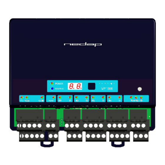
Page 8: Connections
Velos cable OUT Light (same connection as IN) Switch Velos cable Figure : I/O of the VP1007. The input and output connections are shown above as an example. Details VP1007 inputs and outputs Power Minus RS232 / 485 RxD / B- Data receive... -
Page 9: Adjustments
5.1 Check after power up Check if the VP1007 has power after power up. This means 3 green LED’s are on, see figure below. For more details about the LED indicators see Appendix D. If LED’s are green, continue with address settings 5.2 Address... -
Page 10: Antenna
Antenna switch off by the software 5.4 Software setup The software in the connected controller determines how the inputs and outputs on the VP1007 are controlled. See manual with the relevent settings to configure the software for this VP1007. When the software setup is done the VP1007 is ready for use. -
Page 11: Advanced
6. The next menu item AS is now indicated. 7. To leave the service menu and return to normal operation, press the button until the display goes blank (press about 4 seconds) VP1007-200PM-00 ISO Reader I/O Manual version 0.4 / Page... -
Page 12: Identification Test Options
Signal level indication option “SF” and “SH” There is a test available to give an indication about the signal received on the reader of the VP1007. This test is separated in a FDX (SF) and HDX (SH) noise indication test. This test is mainly used for HDX because at HDX there is a greater risk of external influence on the antenna field. -
Page 13: Trouble Shooting
Most of the time when a variable-frequency drive is causing a problem it is due to bad installation or without the mandatory main filters. VP1007-200PM-00 ISO Reader I/O Manual version 0.4 / Page... -
Page 14: Maintenance, Cleaning And Disposal
No regular maintenance required. Software update A VP1007 is equipped with software to activate inputs and outputs, display / push button and a motor safeguard. This software is called firmware. During manufacturing the firmware is programmed and ready for use. In case of an update it is possible to download new firmware thru the CAN-bus. In the Velos system the web browser interface of the VPU (VP8001) is used to handle this. -
Page 15: Appendix A: Specifications
Twisted pair min. 0.34mm shielded Total max. 500m Always use a NEDAP power supply The Nedap guarantee-regulations are only valid when is installed as indicated in this manual. Install data cables at a safe distance from (high) powered cables More information For more detailed information contact your local Nedap supplier or check the internet site. -
Page 16: Appendix B: Display And Push Button
Check a setting select the item to check, press button until blinking, first value shown is actual setting The display is normally automatically switched off after 30 minutes. VP1007-200PM-00 ISO Reader I/O Manual version 0.4 / Page... -
Page 17: Appendix C: Overview Display Menu
Shows error code TEST OUTPUT L1 … L5 TEST INPUT I1 … i5 REMARK Press button until blinking To leave menu: Short press on button Press button until display goes blank VP1007-200PM-00 ISO Reader I/O Manual version 0.4 / Page... -
Page 18: Appendix D: Led Indicator Overview
TUNING /ID Green on Antenna ok Green blinking Antenna ok and tag identified Red on Antenna not tuned correctly Red on Antenna not tuned correctly Red blinking Antenna error / not connected VP1007-200PM-00 ISO Reader I/O Manual version 0.4 / Page... -
Page 19: Appendix E: Rs485 Connection
Appendix E: RS485 connection Power supply RS 485 port of computer RS485 cable specifications (computer to first VP1007): Wires : min. 0.34 mm twisted pair shielded Max length between computer and VP1007 100m. Longer length depends on used baudrate used. -
Page 20: Appendix F: Rs232 Connections
Appendix F: RS232 connections Power supply RS 232 port of computer RS232 cable specifications : Shielded cable Wires min. 0.34 mm Max length between Computer and VP1007 3m. VP1007-200PM-00 ISO Reader I/O Manual version 0.4 / Page...