Table of Contents
Advertisement
Quick Links
Advertisement
Table of Contents
Troubleshooting

Related Manuals for HandTop HT3020UV-C-K


Summary of Contents for HandTop HT3020UV-C-K
- Page 1 HandTop Flatbed Ink Jet Printer Operation Manual HT3020UV-C-K...
-
Page 2: Table Of Contents
Table of Contents HT2512UV FG Kyocera Flatbed Inkjet Printer................错误!未定义书签。 Operation Manual..........................错误!未定义书签。 Foreword....................................1 Safety Precautions..........................错误!未定义书签。 1. Indications of symbols.......................... 4 2. Precautions of operations........................4 Brief introduction................................. 6 1. Printer Applications..........................6 2. Printer Features............................6 3. Printer Configurations...........................7 4. Structure Diagrams..........................8 4.1 Front-view of the printer........................ - Page 3 1. Periodic maintenance for printer parts............错误!未定义书签。 2. Maintenance of the mechanical parts............. 错误!未定义书签。 3. Precision part maintenance................错误!未定义书签。 4. Printhead maintenance..................错误!未定义书签。 4.1 Daily routine maintenance................错误!未定义书签。 4.2 Printhead preservation during power failure..........错误!未定义书签。 4.3 Printhead preservation during long vacation..........错误!未定义书签。 5.
-
Page 4: Foreword
Foreword The UV inkjet printer is a precision machine equipped with extremely fine mechanisms and integrated circuit. With a view to use the printer in an optimal condition, we sincerely compiled this operation manual for your reference. This manual has been prepared for end users’ easy understanding and using of this printer safely and efficiently. -
Page 5: Indications Of Symbols
1. Indications of symbols Note the specific features given with these symbols in order to avoid property damage and personal injury in the operating process. 2. Precautions of operations Caution Please supply the printer with rated voltage and frequency, improper power input may cause functional abnormality or damage to the printer. - Page 6 Never use the printer in a non-ventilated or stuffy workplace, or it may lead to toxic hazards to operators. A ventilator is always a necessity. Any disassembly or replacement of the parts and cables is strictly prohibited in the state of power-on.
-
Page 7: Brief Introduction
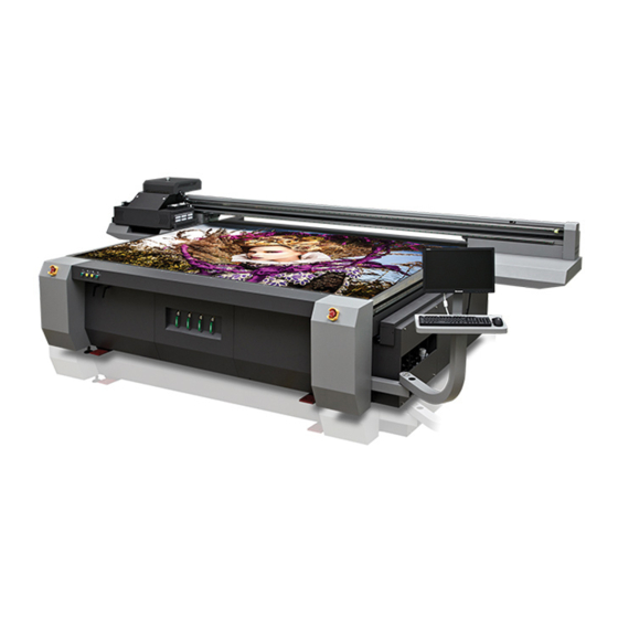
Brief introduction 1. Printer Applications The UV digital printer is able to print directly on diversified media. The model can be used in advertising production such as banner, panel led, POP stand, vinyl display, meanwhile make creative innovation to the traditional craftwork in the decoration industry, of which fine-art glass, wooden products, natural or artificial leather, ceramic tiles and wallpaper, etc, can also be printed on. -
Page 8: Printer Configurations
3. Printer Configurations Model HT2512UV-FK Kyocera Flatbed Inkjet Printer Printhead type Kyocera high-performance drop-on-demand piezo heads Printhead array 2-4 Pcs Maximum resolution 1200*1200 dpi Printing speed 4 Pass 6 Pass 8 Pass 4 head Print size 2.5m in width by 1.2m in length Media type Hard and soft materials Printed thickness... -
Page 9: Structure Diagrams
4. Structure Diagrams 4.1 Front-view of the printer 1. Carriage 2.Front-left emergency stop 3.Equipment control panel 4.Suction control panel 5.Front-right emergency stop 6.Electrical cabinet 7.PC on/off button 4.2 Rear view of printer 1.Rear-right emergency button 2. Main ink tank cabinet 3.Blower exhaust outlet1 4.Blower exhaust outlet2 5.Rear-left emergency button... - Page 10 1.Equipment power button 2.Alignment/registration pin lever 3.Table suction /blow change-over lever 4.Suction on/off button 4.4 Carriage 9 / 97...
- Page 11 1. Belt 2.Anti-crash sensor 3.Ionizer 4.Spindle 5.LED Lamp 6.Color ink purge button 7.Waste ink tray 8.Kyocera Print head 9.White ink purge button 4.5 Table suction control area Front-Left Table Suction Zone Valve Rear-Left Table Suction Zone Valve Rear-Right Table Suction Zone Valve Front-Right Table Suction Zone Valve 4.6.
- Page 12 1. White steering pump 2. Main ink tank 3. Capsule filter 4.7 Negative system 1. Color negative pressure pump 11 / 97...
- Page 13 2. Color air charge pump 3. Color air discharge pump 4. Auto negative control board 5. White air charge pump 6. White air discharge pump 7. White negative pump 4.8 Electrical system 1.24V power supply 2.DC﹢24V power supply fuse 3.DC﹢24V terminal block 4.Relay(Sub ink tank heating &...
- Page 14 7.AC220V power supply fuse 8.Surge filter(Blower1&2) 9.Wave filter 10.Isolating transformer 11.External device board 12.27V power supply 13.24V power supply 14.X axis servo driver 15.Y axis servo driver(left) 16.Y axis servo driver(right) 17.Grounding terminal block 4.9 Equipment symbol diagram 13 / 97...
- Page 15 14 / 97...
- Page 16 15 / 97...
- Page 17 1.Equipment working conditions The space of the workshop should be 7.5m in width by 5m in length at the minimum Constant humidity of 30﹪~70﹪RH Clean and dust-free Sheltered from sunlight In a good ventilating condition ...
- Page 18 1. Pre-installation Prepare the working field under previous instruction 17 / 97...
- Page 19 PCI-E plug supported ≥8G ≥500G Windows7 64 BIT Handtop control software is not available in Windows8 and Windows10 system for the time being 2. Transportation and unload 3.1 Site transport Equipment size & weight 1800 kg 5220mm(L) * 2710 mm(W) * 1380mm...
- Page 20 The loading and transport of the machine would require forklift with more than 8T capacity. The distance between the arms should be at lease 2.0m, length of the arms should also be at least 2.0m (No less than the package box width) .
-
Page 21: Installation Instructions
Disable the screws on wooden package. 4.Installation instructions 4.1 Check and acceptance Verify that all electronic units and mechanism are in normal state as soon as the printer is placed properly. Disassemble all the fixtures of the printer. ... - Page 22 When adjusting the level on the right/left side, the level should face the same direction. 水平仪放置位置示意图 1. There are 6 main supporting foot cups on the machine body. First, raise up all the foot cups, and lower down the 4 foot cups in the corner of the frame, make sure they touch the ground. Jack up the foot cups until the yellow base leave the ground (5mm height would be enough) 2.
- Page 23 4.3 PC & accessories installation Install PC monitor holder, and put the USB PC on/off cable, monitor cable, power cable then put inside the electrical cabinet. Install PCIE card into the PC main board slot,connect the movement control cable to the external device board. 4.4 UV LED lamp assembly 22 / 97...
- Page 24 4.4.1 LED assembly Unpack the LED lamp carefully, install the lamps to the LED housing, connect the power cable, shutter control cable, anti-crash sensor cable. Anti-crash system should always lower 0.5mm than the carriage plate. *How to adjust the carriage to 2mm Put a piece of acrylic on the platform ,then run a nozzle test to detect the height(default height is 2MM), loose the screws of the anti-crash plate, use 1.5mm thickness guage to adjust the height of the plate.
- Page 25 (图一) (图二) (图三) (图四) Connect the re-circulation tube to the inlet and outlet of the chiller(no particular order) then tighten the tubes. 24 / 97...
-
Page 26: Power Input
4.4.3 Chiller setting 1. Current water temperature 2. Power switch 3. Temperature setting 4. Add button 5. Setting button, long press for 3s for the temperature setting adjust (default 25℃), press again for the temperature variation range(default 5℃). The set temperature should not be 5℃... - Page 27 Steps: 1.check the parts: Guide rail stand x2 Rear bearing standx2 26 / 97...
- Page 28 Lead screw x2 Block nut(lead screw) 2 Installation of guide rail stand A. dismount the screw 27 / 97...
- Page 29 B. Put the screw on the stand 8 pcs C. Insert two bolts 28 / 97...
- Page 30 D.Mount the guide rail screw. E. Tighten all the screws 29 / 97...
- Page 31 3.Dismount the blocks from X&Y axis A. Dismount Y axis (carriage) block B. Dismount the block from X axis,and take off the slide Note:Beam is not fixed at this time, it can be pushed just by hand. Be aware of the beam slides backward, and slipped off the guide rail! 30 / 97...
- Page 32 4.Install rear bearing stand A. Loose the screws under the guide rail stand B.Mount the screws, then inset the bolts, and tighten the screws 31 / 97...
- Page 33 5.Install left lead screw A. Dismount the screws front the front bearing stand B. Put on the glove, and place the lead screw in position, mount the front,rear bearing stand screw, then insert the bolt 32 / 97...
- Page 34 Note: When lifting and placing the lead screw, the driver can not be forced in any kind, hold the front bearing stand or the lead screw it self, to avoid damaging the driver! C. Install the limit switch in the end of the Y axis, it positioned on the rear bearing stand. 33 / 97...
- Page 35 6.Install right lead screw A. Loose the screws from the front bearing. B. Use a rope to hang the back side of the lead screw, (two individuals are required) then place the lead screw onto position with the front bearing stand together 34 / 97...
- Page 36 7.Tighten the block nut A. Push the beam to the end of the front. B. Use allen wrench to rotate the screw in the end of the left&right lead screw, push the block nut to the front. 35 / 97...
- Page 37 C.Dismount the block from the right lead screw D. Tighten the three screws from the block nut( both lead screw has to be parallel) 36 / 97...
-
Page 38: Software And Driver Installation
5.Software and driver installation 5.1 Topjet installation 1. Double click the TopJet package for your model Select language 37 / 97... - Page 39 The latest Topjet version only support 64bit Select communication way 38 / 97...
- Page 40 Select equipment model Select print head DPI 39 / 97...
- Page 41 Select print head row(s) 40 / 97...
- Page 42 Select UV lamp type Select Topjet directory(C drive is not recommended 41 / 97...
- Page 43 Select shortcut Finish 42 / 97...
- Page 44 等待完成安装。 43 / 97...
- Page 45 Select Agreed to proceed Finish Install USB communication driver 44 / 97...
- Page 46 Accept and Next Next 45 / 97...
- Page 47 Finish, reboot the PC. 46 / 97...
- Page 48 5.2 Topjet features instruction 5.2. Main interface Features Functions instructions Y&X control Stop/cancel button Carriage Up & Down, Zero position calibration. Diagnosis Printing list Finished list Print button X & Y zero position setting White and Varnish output, this model is not supported in this model Parameter setting 47 / 97...
- Page 49 Calibration print list Copy print 5.2.2 Test and calibration interface Features Functions instructions X/Y stepping setting Print head spraying function Topjet version/SN 1. Nozzle test:printing head nozzle status 2. Vertical calibration:Print head left&right physical adjustment 3. Nozzle alignment:Print head front&rear physical adjustment 4.
- Page 50 6. Bidirectional offset:print head bidirectional calibration 7. Stepping calibration:print head pass adjustment 8. Base pintor calibration:X&Y zero position setting. 9. Voltage&temperature calibration:color difference adjusment Carriage speed selection 1. L_Calibration:L_Calibration adjustment value 2. R_Calibration:R_Calibration adjustment value 1. Speed Ratio:Carriage speed adjustment value 2.
- Page 51 5.2.3 Printing mode interface 50 / 97...
- Page 52 Features Functions instructions 1.X&Y zero position setting value; 2.X&Y printing position setting value。 1. Fill:Print at blanks with white color 2. Base:Print with white color as a base layer of the whole image 3.Base of image:Print with white color as a base layer of other colors.
- Page 53 Copy print: copy multiple images 5.2.4 Control parameter setting Features Functions instructions 1. Spray cleaning:Print head will do ink jetting when carriage is in home station 1. Movement control:Machine printing movement control 2. Print after height detection:carriage will start print automatically after height detection 3.
- Page 54 1. Negative pressure:Color&white negative pressure setting; 2. Negative pressure value:0.5~10Kpa; 3. Default negative setting:-4.5Kpa。 4. Ink box temperature:Sub tank heating temperature setting, default:40 degrees; 1. 1. UV lamp shutter working mode: Control the left and right lights to move left and right respectively. Only the option selected will open the corresponding shutter accordingly.
- Page 55 5.2.5Control parameter interface-LED light on / off position setting The adjustment password for the position of the LED light switch is ua13. After inputting, click Check to open the fine-tuning setting function.The eight parameters on the left are fine-tuning parameters, the unit is millimeters; the parameters are described in detail as follows: Position adjustment of left light on (mm) when the cart moves to the right and position adjustment of left light off (mm) when the cart moves to the right:According...
- Page 56 to the right. 55 / 97...
- Page 57 “set” area and then click “Set” button to adjust heads’ temperature and voltage. The last option is for waveform. Click and chose from the drop-list. If you use Handtop F series ink, chose F-series, and click “write” to set the waveform. That will need to wait 20 second to write the waveform.
- Page 58 57 / 97...
- Page 59 Print heads calibration and alignment 6.1 Print head installation This operation should done by trained operator, to avoid body injury or parts damage Print head cables should be connected when power off, make sure no ink or any liquid on the cable before connected. No squeeze or pressure to the print head Print head spare parts Print head connection...
- Page 60 Ink tube and filter connection Print head connector 59 / 97...
- Page 61 Preparation Flush ink tubes with flushing liquid. 60 / 97...
- Page 62 Disconnect the block 61 / 97...
- Page 63 Connect ink tubes Next 62 / 97...
- Page 64 Ink tube installation finished Dismount the protective cover of the print head 63 / 97...
- Page 65 Peel off the print head cover Install the print head in to the carriage plate Use syringe to flush the print head with flushing liquid 64 / 97...
- Page 66 Exhaust the remaining flushing liquid with syringe Cable connection, white cable is for power supply, Grey cable is for data transmission 65 / 97...
- Page 67 6.2 Ink filling After print head installation, check the connection of the tubes and cables before filing the ink。 Turn off spray cleaning function, lower the negative pressure to -1.2kpa, in case of ink over flow. Fill ink into the main ink tank, and make sure ink pump power cable is connected properly.
- Page 68 6.3 Air exhausting of the printhead The exhausting operation should be done the first time of printhead installation; this operation can help exhaust the air bubbles in the chamber. This operation can also be used to deal with the nozzles missing problem. ...
- Page 69 6.5.1 Vertical alignment Run the TopJet program and then click the “Set” button to enter the “printer parameters setting” interface. Select the printhead vertical alignment in the drop-down-list of the alignment checking and run printing. Use the magnifier to observe the upper and lower parts of the small iron printed and sees whether the two parts merge into a complete one.
- Page 70 6.5.2 Horizontal alignment Select the horizontal checking in the drop-down-list of the alignment checking and run printing. The printing result is shown as below. Note: Since K and C are on the same printhead and M and Y on the other printhead, it is only necessary to perform horizontal alignment with H1 to H3 or H1 to H5.
- Page 71 line, repeat the two steps above accordingly. Fasten the screw ① when the horizontal alignment accomplished. 70 / 97...
- Page 72 6.5.3 Left and right heads offset Left-dir heads offset means color calibration of left-directional print, right-dir heads offset means color calibration of right-directional print. Select the “left-dir heads offset” in the drop-down-list of calibration and alignment Find out the best aligning icon of the print and take it as a variable adding to original value.
- Page 73 Bi-directional calibration 6.5.4 Select the “bi-directional offset” in the drop-down-list of calibration Find out the best aligning icon of the print and take it as a variable adding to original value. Change the value until lines are overlapped perfectly How to check Bi-directional calibration test +3 is the best +3,18+3=21 Stepping calibration...
- Page 74 Change the values on stepping calibration Repeat 1,2,3 until lines are overlapped perfectly How to check stepping calibration test Aligned Change the values accordingly Base position(datum mark) calibration 6.5.6 Select the “print base position” in the drop-down-list of calibration and alignment Measure the distance between the datum checking print and the mechanical base point.
- Page 75 Reset the value of the zero position in the layout option. Illustrated as below. 6.6 Calibration confirmation 74 / 97...
- Page 76 Print this image after the calibration 7. White ink print mode 7.1 Not print No white ink discharging when there is no white color required in the image output. 7.2 Overcoat 75 / 97...
- Page 77 Print at blanks with white color 7.3 Middle layer Image-white-image three layer print, the white layer divides the two sides printed. Applied in some transparent media. 7.4 Base Print with white color as a base layer of the whole image 76 / 97...
- Page 78 7.5 Fill Print at blanks with white color 7.6 Middle layer of image Colors-white-colors three layer print, the white layer divides the two sides printed. Applied in some transparent media. 7.7 Overcoat of image Print with white as a color layer above the other colors 77 / 97...
- Page 79 7.8 Base of image Print with white color as a base layer of other colors 7.9 Color replace Print with white as a substitution of the other colors. 78 / 97...
- Page 80 7.10 Spot Set the white as spot, and output in spot mode 7.11 Middle layer of spot Colors-white-colors three layer print, the white layer divides the two sides printed. Applied in some transparent media. 7.12 Overcoat of spot Print with spot as a color layer above the whole image 79 / 97...
- Page 81 7.13 Base of spot Print with white spot as a base layer of other colors 80 / 97...
- Page 82 ※Operating instructions 1.Start-up operation The user has to go through the safety precautions in chapter Six before the first-time operation. And all operations to be done by beginners must be executed under the instructions of professional technicians. In case of emergency, Press the emergency stop button, machine will power off immediately Note.
- Page 83 Buzz indications and troubleshooting Please go to 2.Printer shut down Print the nozzle check on an A4-size paper and compare with the previous one. Turn off blower and UV lamp Verify that the negative pressure reads normally and the automatic spray function ...
- Page 84 ※Printer maintenance Periodic maintenance With a view to keep the printer in good working conditions, operators should do the maintenance job periodically according to the following instructions. clean the frame clear away the waste ink clean the bottom of the printhead tray check the negative pressure system nozzles checking.
-
Page 85: Maintenance Of The Mechanical Parts
lubricate the rolling and moving mechanical parts Monthly check the joints of ink lines and air lines Maintenance replace the air pump replace the capsule filter Quarterly Maintenance replace the ink pump and optical fiber. replace the quartz glass of the UV lamp assembly Yearly replace the print head filter Maintenance... -
Page 86: Precision Part Maintenance
3.Precision parts maintenance All precision parts must be strictly cleaned with isopropanol and lint-free tissue according to the maintenance instructions. Encoder strip Encoder reader Precision parts Head height reader 4.Print head maintenance 4.1 Daily maintenance Every day before or after work, take a nozzle checking print and see if there is any blockage. -
Page 87: Replacement Of Consumable Parts
4.2 Print head preservation maintenance Get a KT board the size of the printhead tray and wrap it with preservation film. Carefully lay some lint-free tissue on the surface and use some flushing to moisture it. Put the moisturized KT board under the printhead tray, then roll the Z-directional screw lead manually, making the carriage lowing down till the two surface adhere to each other. -
Page 88: Ink Refill
Replace new pump Cut the deformed heads of the tubes; Then reconnect them to the new pump The buzzer might probably generate three-consecutive buzz in the process of replacing. You will need to reset in the Topjet after 5.2 ink refill When the hearing six-consecutive buzz, check and see if the ink is running out. -
Page 89: Replacement Of Air Pump
5.3 Replacement of capsule filter The ink filter requires seasonal replacement. Disconnect the power cable connects of the ink pump. Clamp the inlet tube so as to avoid ink leaking or withdrawal. Disconnect the joints of the tube and the filter. Remove the filer. Replace with a new one and pay attention to the flow direction indicated by the arrow mark on the filter. - Page 90 Turn off the scram stop and disconnect the power cables of both air pumps. Disassemble the cover of the towline. Replace the used tubes with new ones. Mark the tubes accordingly so as to avoid incorrect connection. Connect and fix the tube properly. Reassemble the cover of the towline.
-
Page 91: Troubleshooting
※Trouble shooting Buzz indications and troubleshooting There are six kinds of buzz alert programmed in the printer. Buzz type Buzz indication Troubleshooting Single buzz The main air pump stops Check if the main air pump is still in proper working and the backup air use, and check the reading values of the pump activate. -
Page 92: Printhead Strike
2.1 Ink purging failure Indication Ink is not purging when press the ink purge button Check the solenoid valves Troubleshooting accordingly Check sub tank is empty ( three beeps) Check the positive pressure 3.Printhead strike 3.1 How to avoid head strike The automatic head height adjustment must be run whenever changes material. - Page 93 When printing on some heat-formative materials, shut the non-used suction sectors of the platform. And cover the tiny holes of air leaking, so as to decline the possibility of deformation by strengthen the corresponding suction. There is a certain distance between the head height detecting position and the datum point. If the printed is too small to be detected when placed near the datum point, you may try and put the media on the location for head height founder first and then move it to the printing position when head height adjustment accomplishes.
- Page 94 3.2 Dealing with print head strike Wait for the error message to appear on the computer screen before taking any corrective action,Click “Yes” in the error message dialogue. Lift the carriage and remove the media. Reset the anti-crashing device. Control the printer back to the standby position. Restart printing job.
-
Page 95: Carriage Moving Malfunction
4.Carriage moving malfunction 4.1 Servo driver error code There are usually error messages displayed in the servo driver, deal with the issue according to the corresponding information. Order Code Indication Troubleshooting oc1 or oc2 Current overload Check and see power connection of the motor oL1 or Overload... -
Page 96: Cache Problem
4.2 Cache problem (The carriage pause too long at the two ends of the lead rail during the printing process.) There might be two aspects that cause this problem, below are the causes explanations and solutions. Excessive image size or excessive file gross result in long data processing, and thus relate to printing data transmitting slowdown. -
Page 97: Tools And Materials Needed
Do the calibration again Color deviation Adjust the total ink limit by 10%-30%. Check color calibration The printed image Adjust the brightness by 3-6 appears dark Select all options in the vector image. This method only effects in vector image printing.