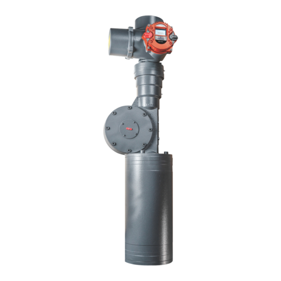
Emerson Bettis RTS Installation, Operation And Maintenance Manual
Additional board for bettis rts actuators
Hide thumbs
Also See for Bettis RTS:
- Installation, operation and maintenance manual (26 pages) ,
- Service manual (18 pages) ,
- Installation, operation and maintenance manual (16 pages)
Summary of Contents for Emerson Bettis RTS
- Page 1 Installation, Operation and Maintenance Manual VCIOM-15590-EN Rev. 0 November 2021 Bettis RTS - PROFIBUS Additional Board for Bettis RTS Actuators...
- Page 2 Installation, Operation and Maintenance Manual Notes November 2021 VCIOM-15590-EN Rev. 0 This page intentionally left blank...
-
Page 3: Table Of Contents
Installation, Operation and Maintenance Manual Table of Contents VCIOM-15590-EN Rev. 0 November 2021 Table of Contents Section 1: General Information General Information ....................1 Section 2: Connection Standard Design .................... 2 2.1.1 Terminal Board (Provided by customer) ..........2 2.1.2 Connecting the PROFIBUS Cables ............ - Page 4 Installation, Operation and Maintenance Manual Notes November 2021 VCIOM-15590-EN Rev. 0 This page intentionally left blank...
-
Page 5: Section 1: General Information
November 2021 Section 1: General Information The Standardized PROFIBUS DP system is available for all Bettis RTS Series of actuators. This interface is a hardware option and should already be known when ordering the actuator. Retrofitting is possible but should only be performed by a skilled Emerson technician or by specially trained personnel. -
Page 6: Section 2: Connection
Section 2: Connection Installation, Operation and Maintenance Manual November 2021 VCIOM-15590-EN Rev. 0 Section 2: Connection Depending on the order, there are the following connection options: • Standard design: via terminal board • Explosion-proof design: via terminals Standard Design PROFIBUS cables connect via the input/output board in the terminal compartment for the customer’s plug connector for the actuator. -
Page 7: Connecting The Profibus Cables
Installation, Operation and Maintenance Manual Section 2: Connection VCIOM-15590-EN Rev. 0 November 2021 2.1.2 Connecting the PROFIBUS Cables Recommended cable assembly Before connecting the bus cable, it has to be assembled as follows: The terminals on the terminal board are designed for a max. cross-section of up to 1.5 mm The shield outside diameter has to be in the range of 5 - 8 mm. - Page 8 Section 2: Connection Installation, Operation and Maintenance Manual November 2021 VCIOM-15590-EN Rev. 0 Customer connection at the end of the line, bus termination There are no further PROFIBUS subscribers before or after the slave. Connection for the cables: Figure 4 Single Channel Figure 5 Dual Channel...
-
Page 9: Explosion-Proof Design
Generally, no bus termination is provided in the BETTIS RTS in the explosion-proof design, i.e., the bus has to be implemented on both ends on the system side. As an option, however, the bus connection can also be implemented in BETTIS RTS. This has to be specified when ordering. -
Page 10: Section 3: Commissioning
The GSD file contains information about the device’s properties needed by the master. The current GSD file can be downloaded at Emerson Global Sales Portal. After that, the user can configure and parameterise each device on the PROFIBUS-DP. -
Page 11: Section 4: Description Of The Input And Output Data
Installation, Operation and Maintenance Manual Section 4: Input and Output Data VCIOM-15590-EN Rev. 0 November 2021 Section 4: Description of the Input and Output Data General information: Depending on the master, it is possible that the low byte (bit 0 - 7) and the high byte (bit 8 - 15) might have to be swapped. -
Page 12: Setpoint
Section 4: Input and Output Data Installation, Operation and Maintenance Manual November 2021 VCIOM-15590-EN Rev. 0 4.1.2 Setpoint Module number: 22 ID-byte: 60 (1 word AA / consistency 1 word) Data format: 16-bit, the lower 10 bits (0 - 1023) are used. The other bits are reserved for future use and have to be set to zero! Structure: Table 4. -
Page 13: Set-Point Speed
Installation, Operation and Maintenance Manual Section 4: Input and Output Data VCIOM-15590-EN Rev. 0 November 2021 Table 6. Bit-setting for intermediate position (Bit8) Bit11 Bit10 Bit9 Function move to intermediate position: Position 1 move to intermediate position: Position 2 move to intermediate position: Position 3 move to intermediate position: Position 4 move to intermediate position: Position 5 move to intermediate position: Position 6... -
Page 14: Status
Section 4: Input and Output Data Installation, Operation and Maintenance Manual November 2021 VCIOM-15590-EN Rev. 0 4.2.2 Status Module number: 13 ID-byte: 50 (1 word AA / consistency 1 word) Data format: 16-bit (bit field) Structure: Table 8. Description Bit no. Function Bit = 0 Bit = 1... -
Page 15: Actual Speed
Installation, Operation and Maintenance Manual Section 4: Input and Output Data VCIOM-15590-EN Rev. 0 November 2021 4.2.4 Actual Speed Module numbe: 15 ID-byte: 50 (1 word AA / consistency 1 word) Data format: 16-bit, only the lower 8 bits are used (bit 7: direction OPEN; bit 6 - 0: 0 - 100 corresponding to 0 - 100%) The other bits are reserved for future use and have to be hidden! 4.2.5... -
Page 16: Status 3
Section 4: Input and Output Data Installation, Operation and Maintenance Manual November 2021 VCIOM-15590-EN Rev. 0 4.2.7 Status 3 Module number: 18 ID-byte: 50 (1 word AA / consistency 1 word) Data format: 16-bit, error number Table 10. Error Code Meaning Motor temperature warning Motor temperature cut-out... -
Page 17: Bi-Directional Data (Master To Slave And Slave To Master)
Installation, Operation and Maintenance Manual Section 4: Input and Output Data VCIOM-15590-EN Rev. 0 November 2021 Bi-directional Data (Master to Slave and Slave to Master) 4.3.1 Parameter Channel In/Out Not currently supported! Module number: 30 ID-byte: F1 (2 word AE / AA / complete consistency) Data format: 32-bit, parameter number, parameter value Input and Output Data... - Page 18 P. R. China Székesfehérvár 8000 T +86 22 8212 3300 Hungary The Emerson logo is a trademark and service mark of Emerson Electric Co. T +36 22 53 09 50 Bettis is a mark of one of the Emerson family of companies.


