Table of Contents
Advertisement
Available languages
Available languages
Quick Links
Advertisement
Table of Contents

Related Manuals for Ducati DRT 2100


Summary of Contents for Ducati DRT 2100
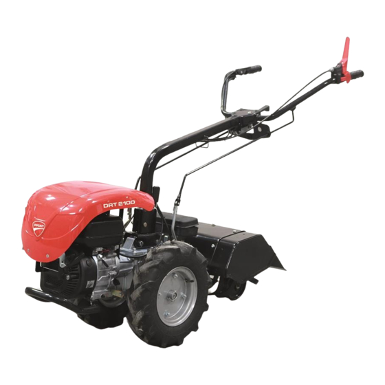
- Page 1 DRT 2100 PETROL POWER ROTOTILLER Owner’s manual...
- Page 3 Español Atención • Antes de usar nuestra máquina, por favor lea este manual cuidadosamente para saber cómo usar correctamente esta unidad. •Tenga este manual a mano.
-
Page 4: Table Of Contents
Contenido 1. Identificación del motocultor 2. Información de seguridad 3. Símbolos de seguridad 4. Instrucciones de seguridad 5. Mandos e instrumentos 6. Uso 7. Mantenimiento 8. Datos técnicos 9. Rotocultor 10. Barra de corte Simbología en la máquina (P. 70) -
Page 5: Identificación Del Motocultor
Español Manual de usuario Gracias por adquirir nuestra máquina. Este manual contiene información sobre el uso y el mantenimiento, que está basada en la información más reciente sobre el producto disponible en el momento de su aprobación para su impresión. Nos reservamos el derecho a realizar cualquier cambio sin notificación previa y sin incurrir en cualquier obligación posterior. -
Page 6: Símbolos De Seguridad
Español Manual de usuario cuidadosamente. Esta información sobre seguridad le avisa de que existe un peligro potencial para usted así como para los demás. Las palabras clave están marcadas con un “!” situado delante de la información a destacar. Estas palabras son “Danger, Warning, Attention”/ “Peligro, Aviso, Atención” . DANGER / PELIGRO Si usted no sigue las indicaciones contenidas en este manual, puede sufrir serias lesiones e incluso la muerte. -
Page 7: Instrucciones De Seguridad
Español Manual de usuario Regulación del carburador. "H" para velocidad alta, "L" para velocidad baja. El motor funciona a velocidad variable continuamente. Nivel máximo de potencia de ruido ponderado con A. Utilice el conmutador del motor. Conmutando el interruptor a la posición STOP hará que el motor se detenga inmediatamente. - Page 8 Español Manual de usuario Repostaje de combustible Presta atención al fuego. Por favor, mantenga el tanque de combustible lejos de las llamas o chispas. No fume cerca del combustible. Está prohibido repostar con la máquina en funcionamiento. - Abra la tapa del combustible con cuidado para permitir que cualquier acumulación de presión en el tanque se libere lentamente y evite el derrame de combustible.
- Page 9 Español Manual de usuario -No acercar las manos, los pies ni la ropa a las partes móviles o giratorias. - Conducir siempre con el debido cuidado y atención. - No usar la máquina si los dispositivos de seguridad no funcionan perfectamente. - No modificar nunca por ninguna razón los dispositivos de seguridad.
- Page 10 Español Manual de usuario 1) Dispositivo de seguridad de acoplamiento inverso; evita que se conecte la marcha atrás cuando la TDF está acoplada. Si la máquina tiene marcha atrás, esta no se activará si se está trabajando con la azada giratoria o con la barra de corte delantera.
- Page 11 Español Manual de usuario Mientras opera - No utilice nunca la máquina cerca de transeúntes, especialmente niños. - Familiarícese con los controles y aprenda a apagar rápidamente el tractor para caminar utilizando el dispositivo de parada del motor. - No utilice nunca la azada rotativa sin la cubierta protectora. - Nunca acerque las manos o los pies a los componentes de la máquina mientras estén en funcionamiento.
- Page 12 Español Manual de usuario 5. MANDOS Y CONTROLES Fig.1 - Controles del tractor para caminar 1) Palanca de cambio de marchas. 6) Palanca de ajuste vertical del manillar. 2) Palanca de la TDF. 7) Palanca del acelerador. 3) Palanca de embrague. 8) Palanca de mando para acoplar rápidamente los implementos a la TDF 4) Palanca del dispositivo de...
- Page 13 Español Manual de usuario Figura 2: pegatina en la paleta de la barra de mano que muestra la distribución de la palanca de cambios, la conexión de la TDF y la liberación de la barra del manillar lateral. 2) Palanca selectora de modo de TDF Esta palanca tiene dos posiciones: TDF en reposo (NEUTRAL)
- Page 14 Español Manual de usuario N.B .: los manillares deben girarse de la siguiente manera (ver la pegatina en la columna del manillar) a) Gire el manillar en sentido horario para cambiar de la posición normal a la posición de marcha atrás.
- Page 15 Español Manual de usuario ADVERTENCIA Desactive la PTO y apague el motor antes de conectar, desconectar, limpiar o ajustar los implementos conectados a la PTO. Fig.4- Palanca de control para acoplar rápida- mente los implementos a la TDF. 8) Palanca de seguridad de marcha atrás (Fig.5) El tractor para caminar tiene un dispositivo de seguridad (9) (Fig.
- Page 16 Español Manual de usuario 1 ) Tractor andante con implemento frontal (Fig.5). -Presione las palancas (A) para permitir que el dispositivo de venta (9) se mueva libremente. -Gire la palanca hacia abajo (9) en la posición de corte (ver Adhesivo) para permitir que se active la marcha atrás.
-
Page 17: Uso
Español Manual de usuario 6. USO Consulte el manual de uso y mantenimiento del motor para obtener información completa sobre el funcionamiento del motor. ADVERTENCIA - El tractor para caminar tiene una palanca (motor de parada) que siempre debe bajarse junto con la palanca del embrague que debe tirarse hacia arriba para arrancar el motor. - Page 18 Español Manual de usuario Arranque del tractor para caminar (Fig. 1-6) ADVERTENCIA - Utilice los mandos de la máquina sólo desde el puesto de dirección. -Antes de comenzar a trabajar, inspeccione siempre cuidadosamente el área de trabajo para identificar cualquier fuente de peligro y tome medidas para eliminar o limitar los riesgos. -Sólo opere la máquina después de haberse asegurado de que nadie esté...
- Page 19 Español Manual de usuario 1 7x14 DIN 5482 con giro a derechas y situado en la parte trasera de la carcasa del cambio. Fig.7 - Toma de fuerza La TDF se acciona directamente desde el motor y su funcionamiento es totalmente independiente del avance del tractor.
- Page 20 Español Manual de usuario ADVERTENCIA - Arranque el motor con la palanca de la TDF en punto muerto. - Cuando no se usa la PTO, mueva la palanca de la PTO a la posición neutral. Fig.8 - Palanca de control de la TDF (tractor para caminar normal versión).
- Page 21 Español Manual de usuario 2) Inserte el cubo del implemento (M) en la abertura de la TDF. 3) Continúe girando la palanca (8). Si el implemento se ha enganchado correctamente, volverá automáticamente a la posición inicial, bloqueando el implemento a la TDF. 4) Siga estas instrucciones a la inversa cuando desacople el implemento.
- Page 22 Español Manual de usuario Fig. 11 - Dispositivo de seguridad en "CAMI- NATA NORMAL Posición "TRACTOR" ADVERTENCIA La marcha atrás no se puede utilizar cuando las cuchillas de la azada rotativa están girando, por lo tanto con la TDF acoplada. Fig.12 - Dispositivo de seguridad en el "TRAC- DE PIE CON IMPLEMENTO FRONTAL "posición.
- Page 23 Español Manual de usuario conductor. 4) Vuelva a colocar los tapones (A) en sus respectivos ADVERTENCIA Dado que la máquina puede dar marcha atrás, los controles de la TDF y de la palanca de cambios se invertirán debido al efecto de la rotación cuando el manillar se gira 180 (ver etiqueta en el panel).
- Page 24 Español Manual de usuario Fig.15 - Ajuste de vía con neumáticos y jaula ruedas Cuando se gira el manillar para enganchar un implemento frontal, conviene invertir las posi- ciones de las ruedas para adaptar el nervio a esta nueva dirección de avance (Fig.15). La presión de los neumáticos debe compro- barse y ajustarse antes de utilizar el tractor para caminar en el campo.
- Page 25 Español Manual de usuario Motor Motor Cumpla estrictamente con las instrucciones de mantenimiento en el manual del motor suministrado con su tractor en funcionamiento. DESPUÉS DEL FUNCIONAMIENTO DE LAS PRIMERAS 50 CASAS 1) Cambie el aceite en la carcasa de la caja de cambios. Esto debe hacerse en una superficie nivelada cuando el motor esté...
-
Page 26: Mantenimiento
Español Manual de usuario Fig. 18 - Regulación de la maneta del embrague. 3) El enganche rápido que engancha los implementos a la TDF tiene un lubricador (I) que se debe utilizar para engrasar el enganche utilizado para enganchar otros implementos (Fig. 19). También engrase el eje de la TDF (L) cada vez que acople un nuevo implemento (Fig.19). -
Page 27: Datos Técnicos
Español Manual de usuario 8. DATOS TÉCNICOS Fig.20 - Dimensiones del tractor andante con azada rotativa y barra segadora Embrague Embrague cónico en baño de aceite con mando de palanca. Caja de cambios Mecánico con engranajes de dientes rectos controlados por una palanca que selecciona 2 relaciones de velocidad (1 HACIA ADELANTE + 1 HACIA ATRÁS). -
Page 28: Rotocultor
Español Manual de usuario Velocidad Toma de fuerza La toma de fuerza es del tipo 1 7x14 DIN 5482 estandarizado con un sentido de giro en el sentido de las agujas del reloj. La toma de fuerza se acciona directamente desde el motor y su funcionamiento es totalmente independiente de la dirección en la que se mueve el tractor. - Page 29 Español Manual de usuario Identificación del rotocultor Fig. 1 - Tipo y número del chasisindicado en la placa de características del capó (A). Reglas de seguridad ADVERTENCIA - Antes de poner en marcha el rotocultor conectado a la toma de fuerza, asegúrese siempre de que los transeúntes se encuentren a una distancia segura de la máquina.
- Page 30 Español Manual de usuario motor de la azada y en el capó: 1) Desmontar los paneles laterales móviles (L) del capó y las tiras niveladoras (P) quitando los tornillos (V) (Fig.2). Fig. 2 - Desmontaje de los laterales y listones niveladores del capó. 2) Ahora reduzca el ancho de trabajo de 500 mm a 400 mm de la siguiente manera (Fig.3): retire las cuchillas (B) y (C) destornillando los respectivos tornillos de fijación.
- Page 31 Español Manual de usuario Fig.4 - Tapón de llenado de aceite y ajuste de la parte de profundidad Mantenimiento DESPUÉS DE LAS PRIMERAS 50 HORAS DE TRABAJO 1) Cambie el aceite de la carcasa de la azada quitando el tapón (G) (Fig. 5) y volcando el propio rotocultor.
-
Page 32: Barra De Corte
Español Manual de usuario 10. BARRA DE CORTE Introducción Al ser reversible, el tractor para caminar se puede convertir rápidamente en una cortadora de motor cuando se conecta una barra de corte a la PTO. La barra segadora se utiliza para cortar céspedes de diversa naturaleza y es muy eficiente, ya que se maneja fácilmente y es liviana. - Page 33 Español Manual de usuario Uso de la barra de corte La barra de corte se acciona mediante la palanca de control de la TDF del tractor para caminar de la siguiente manera: 1) Tirar de la palanca del embrague y enganchar la 1ª marcha con la palanca de cambios.
- Page 34 Español Manual de usuario Fig. 4. Ajuste de la cabeza de la cuchilla. 3) AJUSTE DE LA GUÍA DE LA CUCHILLA (Fig.5) Ajuste periódicamente el juego entre la guía de la cuchilla y la cuchilla para evitar que se vuelva excesivo.
- Page 35 Español Manual de usuario Mantenimiento DESPUÉS DE LAS PRIMERAS 50 HORAS DE TRABAJO 1) Cambie el aceite en la barra de corte (Fig.7). Esta operación debe realizarse con el aceite caliente y la máquina sobre una superficie plana. Deje que el aceite viejo fluya a través del tapón (R) y vierta 0,5 litros de aceite nuevo del tipo (STIMOIL: GEAR POWER ISO 150) a través del tapón (S).
- Page 37 English Attention • Before using this machine, please read carefully this manual to have clear knowledge on how to use the unit. • Have this manual at reach.
- Page 38 Contets 1. Rototiller identification 2. Safety information 3. Graphic warnings 4. Security instructions 5. Instruments and controls 6. Operation 7. Maintenance 8. Technical specifications 9. Rotary Hoe 10. Mowing bar Symbols on the machine (P. 70)
- Page 39 English Owner’s manual Thank you for purchasing our machine and hope that you will enjoy operating your unit. This manual contains information on operation and maintenance of the machine, which is based on the most recent product information available at the time of approval for printing. We reserve the right to make amendments without advance notice and without incurring any obligation for sequences.
- Page 40 English Owner’s manual Safety information gives you warning that you may bring potential danger to yourself and others. The key words with “!” are put before every piece of information. These words are “danger, warning, attention” . DANGER Indicates a danger If you do not follow the instructions, you could suffer personal injury or death. WARNING Indicates the possibility of personal injury or equipment damage if you do not follow the instructions.
- Page 41 English Owner’s manual The motor runs at variable speed continuously. Maximum noise power level weighted with A. Use the motor switch. Switching the switch to the STOP position will cause the motor to stop immediately. Use the switch to turn the machine on or off. Position "O" STOP, Position "I" LIGHT. 4.
- Page 42 English Owner’s manual - Fill the machine with fuel only in well-ventilated areas. If you spill fuel, clean the machine immediately; If fuel falls on clothing, change it immediately. - After refueling, tighten the bolt-type fuel cap as secure as possible. This reduces the risk of unit vibrations by causing the fuel cap to loosen or come out and spill quantities of fuel.
- Page 43 English Owner’s manual Before use Power Take Off (PTO) Before coupling, uncoupling, cleaning or adjusting PTO driven implements, disengage the PTO drive, stop the engine and make sure that the PTO shaft (L) has stopped spinning. NEVER stand between the walking tractor and the implement when operating the controls.
- Page 44 English Owner’s manual right running direction. ATTENTION Before performing the rotation of the manceras it is OBLIGATORY to position the INVERT LEVER according to the direction of travel to allow the operation of the SAFETY DEVICE COUPLING Reverse. 2) Motorstop, device that instantly stops the engine if we leave the driving handlebar. Reversibility The engine must be off when the handle-bar is turned.
- Page 45 English Owner’s manual After use Whenever you make a stop, bring the walking tractor to a complete standstill, engage the parking brake, disengage the PTO, set the gear lever to the neutral position, rest the implement fully on the ground, turn off the engine and remove the key BEFORE leaving the walking tractor.
- Page 46 English Owner’s manual 5. INSTRUMENTS AND CONTROLS Fig.1 - Walking tractor controls 1) Gearshift lever. 6) Vertical handle-bar adlustmenl lever. 2) PTO lever. 7) Accelerator lever. 3) Clutch lever. 8) Control lever to quickly couple implements to the PTO 4) Salety device lever tothe 9) Reversing salety device.
- Page 47 English Owner’s manual Fig.2 - Sticker on the handre-bar paner showing the gearshift, PTO engaging and side handle.bar release layout. 2) PTO mode selector lever This lever has two positions: PTO at standstill (NEUTRAL) PTO operating (INDEPENDENT) 3) Clutch lever (Fig. 1) - Pull the lever = clutch disengaged.
- Page 48 English Owner’s manual Release by pushing the lever (5) forwards (see sticker on panel). N.B.: the handle-bars must be turned inthe following way (see the sticker on the handle-bar column) a) Turn the handle-bar clockwise to switch from the normal position to the reversing position. b) Turn the handle-bar anticlockwise to switch from the reversing position to the normal position.
- Page 49 English Owner’s manual WARNING Disengage the PTO and turn off the engine before connecting, detaching, cleaning or adjusting implements connected to the PTO Fig.4- Contol lever to quickly couple the imple- ments to the PTO. 8) Reversing safety lever (Fig.5) The walking tractor has a safety device (9) (Fig.
- Page 50 English Owner’s manual 1 ) Walking tractor with frontal implement (Fig.5). -Push the lever (A) foMards to allow the salety device (9) to freely move. -Turn the lever downwards (9) in the mowing position (see Sticker) to allow the reverse gear to engage.
- Page 51 English Owner’s manual 6.OPERATION Refer to the engine's use and maintenance manual for comprehensive information on running in the engine. WARNING - The walking tractor has a lever (motorstop) that should always be lowered along with the clutch lever which should be pulled upwards in order to start the engine. - Never ever tamper with the safety device (motorstop) for any reason whatsoever.
- Page 52 English Owner’s manual Starting the walking tractor (Fig. 1-6) WARNING - Only ever operate the machine controls from the steering position. -Before beginning work, always inspect the work area carefulty to identily any sources of danger and take action to eliminate or limit any risks. -Only operate the machine after having made certain that no one is in its operating zone.
- Page 53 English Owner’s manual Fig. 7 - Powser tako-off The PTO is driven straight from the engine and its operation is totally independent of walking tractor advancement. The speeds can be selected by means of the PTO mode selector control lever (2), (Fig. 8-9) which has two positions: NORMAL WALKING TRACTOR version: speed 310 rpm (clockwise) at a 3600 rpm engine rate.
- Page 54 English Owner’s manual Fig. 8 - PTO control lever (normal walking tractor version). Fig. 8 - PTO control lever walking tractor version with frontal implement). WARNING Since the machine is able to reverse, the PTO and gearshift controls will be inverted owing to the effect of rotation when the handle-bar is turned through 1800(see sticker on panel).
- Page 55 English Owner’s manual WARNING Always stop the engine beforo coupling, uncoupling or adlusting the implements. Fig. 10 - Couplins implements to the PTO. Safety device for reverse gear engagement As mentioned in the 'INSTRUMENTS AND CONTROLS' section, the walking lractor is equipped with a safety device (9) that prevents the reverse gearlrom being engaged when the PTO is engaged (Fig.1 1 ).
- Page 56 English Owner’s manual WARNING The reverse gear cannot be used whon the hoes blades of the rotary hoe are spinning, thus with the PTO engaged. Fig.12 - Safety device in the "WALKING TRAC- WITH FRONTAL IMPLEMENT" position. The rotary hoe cannot be coupled in this position. Turning the handle.bars (Fig.
- Page 57 English Owner’s manual Fig. 13 - Turning the handle-bars. Fig. 14 - Turning the handle-bars. WARNING - The engine must be off when the handle-bar is turned. - Make sure that the handle-bar is wellfixed on itsturning stop before beginning work. - When the handle-bar is turned, always position the lever (9) of the safety device according to the runnlng direction, depending on the implement belng used.
- Page 58 English Owner’s manual Fig. 15 - Track adjustment with tyres and cage wheels. When the handle-bars are lurned to hitch a frontal implement, it is advisable to invert the positions of the wheels to adapt the ribbing to ths new fonward direction (Fig.15). The tyre pressure must be checked and ad- justed before the walking tractor is used on the field.
- Page 59 English Owner’s manual Engine Stictly comply with the maintenance instructions in the engine manual supplied with your working tractor. AFTER THE FIRST 50 HOUBS WORK 1) Change the oil in the gearbox housing. This should be done on a level surface when the engine is hot.
- Page 60 English Owner’s manual Fig. 18 - Clutch lever adjustment. 3) The quick coupling that hitches the implements to the PTO has a lubricator (I) which must be used to grease the coupling used to hitch other implements (Fig. 19). Also grease the PTO shaft (L)whenever I new implement is coupled (Fig.19). Fig.
- Page 61 English Owner’s manual 7. MAINTENANCE EVERY 1OO HOURS WORK 1) Check the oil level in the gearbox housing through plug (T), (Fig. 17). This is carried out on a flat surface and with the engine cold. The level should reach between the min.
- Page 62 English Owner’s manual Clutch Cone clutch in oil bath with lever control. Gearbox Mechanical with straighttoothed gears controlled by a lever which selects 2 speed ratios (1 FORWARD + 1 REVERSE). Reduction ratio of the bevel qear pair Reduction bevel gear pair with GLEASON toothing 6/27 = 4.5 Speed Power take-off The PTO is the standardized 1 7x14 DIN 5482 type with a clockwise spinning direction.
- Page 63 English Owner’s manual 9. ROTARY HOE lntroduction The walking tractor can be equipped with different implements in order to meet the most varied requirements. The rotary hoe is the most widely used implement on walking tractors for work in orchards, vineyards and gardens.
- Page 64 English Owner’s manual Use of the rotary hoe The rotary hoe is operated by the PTO control lever of the walking tractor in the following way: 1) Pull the clutch lever and engage the 1st speed by means of the gearshift lever. 2) Pull the PTO lever towards the driver and release it once it has engaged.
- Page 65 English Owner’s manual Work depth adjustment The work depth of the rotary hoe can be adjusted by means of share (E) equipped with regulating plate, after having removed the screw (H). Fit the share (E) back at the desired height and remount the screw (H), (Fig.
- Page 66 English Owner’s manual - WEIGHTS 500 mm. to 400 mm. adjustable rotary hoe = 22 Kg 10. MOWING BAR lntroduction Being reversible, the walking tractor can be guickly converted into a motor mower when a mowing bar is attached to the PTO. The mowing bar is used to cut lawns of varying nature and is very efficient, since it is easily handled and lightweight..
- Page 67 English Owner’s manual Safety rules WARNING - Always mount the blade guard on the mowing bar, both during transport and at the end of work. - Move the PTO control level to neutral position and stop the engine before proceeding with any cleaning, lubricating work or adjustments.
- Page 68 English Owner’s manual 2) ADJUSTING THE KNIFE HEAD (Fig, 4 ) Periodically adjust the play between the knife and ball roller to prevent it from becoming excessive. The correct play is adjusted in the following way: a) Slacken off the bolts (E). b) Use adjuster screws (F) in order to obtain the required play of 0.10 mm between a bolt (F) and the ball roller (H).
- Page 69 English Owner’s manual Mowing bar type E.S.M. (Fig. 6) a) Slacken off the bolts (O) that lock each of the knife guides (P) in place. b) Work on bolt (0) ot each knife guide until the knife slides correctly. c) Re-tighten bolts (0) to tock each knife guide. Maintenance AFTER THE FIRST 50 HOURS WORK 1) Change the oil in the mowing barcasing(Fig.7).
-
Page 70: Simbología En La Máquina
SIMBOLOGÍA EN LA MÁQUINA / SYMBOLS ON THE MACHINE / SYMBOLOGIA NA MÁQUINA SYMBOLOGIE DANS LA MACHINE / SIMBOLOGIA NELLA MACCHINA / SYMBOLOGIE IN DER MAS- CHINE Lea el manual de usuario y comprenda las indicaciones. Read the user manual and understand the instructions. Leia o manual do usuário e compreenda as instruções. - Page 71 Lea el manual para uso y mantenimiento del filtro de aire baño de aceite. Read de manual for use and maintenance of the oil bath air filter. Leia o manual para uso e manutenção do filtro de ar do banho de óleo. Lisez le manuel d'utilisation et d'entretien du filtre à...
- Page 72 Notas / Notes...
- Page 73 Plataforma Logística de Zaragoza (PLAZA) C/ Isla de Ischia, 2-4 50197 ZARAGOZA (Spain) Tfno.: +34 976 786 686 Fax.: +34 976 771 0 53 http://www.ducatigarden.com...