Advertisement
Quick Links
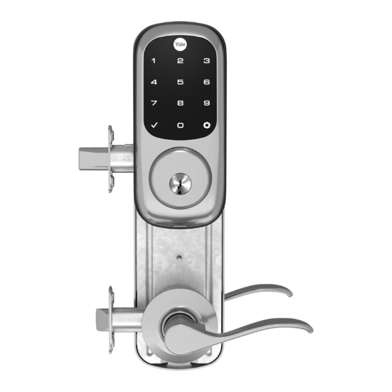
Yale Assure Lock
®
®
Electronic Interconnected Touchscreen
®
Installation and Programming Instructions
(YRC226/YRC426/YRC620)
Inside
Outside
of Door
of Door
4" Touchscreen Shown - 5.5" Available
Network Module
(Optional - Not
Before you begin
available on
YRC620)
DOWNLOAD
THE BILT APP
for step-by-step installation
instructions & to register
your product
Retrofitting or modifying this product may impact fire rating, safety features and warranty.
Consult with code specifications to ensure compliance with all codes and ratings.
1
P/N
YRL EMICL TSINSTL FUL
-
-
-
Rev G
Advertisement

Related Manuals for Yale Assure Lock YRC226


Summary of Contents for Yale Assure Lock YRC226
- Page 1 Yale Assure Lock ® ® Electronic Interconnected Touchscreen ® Installation and Programming Instructions (YRC226/YRC426/YRC620) Inside Outside of Door of Door 4" Touchscreen Shown - 5.5" Available Network Module (Optional - Not Before you begin available on YRC620) DOWNLOAD THE BILT APP for step-by-step installation instructions &...
-
Page 2: Before You Begin
Before You Begin Template Network Module (Optional - Not available on YRC620) 1/8" 3/32" 1/8" 1" 2-1/8" 4-1/2" (114) 1-3/8" (35mm) Min to 1-3/4" (44.5mm) Max YRL EMICL TSINSTL FUL Rev G... - Page 3 Mark Door Reference Lines EXISTING 2-3/8" or 2-3/4" Backset Template YRL EMICL TSINSTL FUL Rev G...
- Page 4 Preparing Door (if necessary) Template 4" 5.5" 2-3/8" Ø2-1/8" Ø1" 2-3/4" Drill holes 1/2 way thru door then complete from other side to prevent splitting. YRL EMICL TSINSTL FUL Rev G...
- Page 5 Installing Strike Plates 7-16 / 8-32 x 1" UNCWS Frame 1" Dia. x 1"Deep Frame Inside of Door 1" Dia. x 1/2"Deep Door Frame YRL EMICL TSINSTL FUL Rev G...
- Page 6 Determining Handing The hand of a door is determined from the secure side of the door. The term "secure" means the side from which you initially unlock and enter. Left Hand “ ”, Hinges Left. Left Hand Reverse " ", Hinges Left. Open Inward.
- Page 7 Changing Handing (if necessary) 4" Left Hand to 4" Right Hand Shown 4-24 x 1/4" PPHMS DO NOT TAMPER WITH OR LOOSEN E-CLIP AND ITS ASSEMBLY DO NOT LOOSEN THESE 6 SCREWS OR REMOVE COVER YRL EMICL TSINSTL FUL Rev G...
- Page 8 Changing Handing (if necessary) continued YRL EMICL TSINSTL FUL Rev G...
- Page 9 Lockset Handing Configurations For 5.5" For 5.5" For 4" 4" Right Hand For 4" 4" Left Hand Test Lever and Thumbturn After handing is changed, check that lever and thumbturn rotate freely. YRL EMICL TSINSTL FUL Rev G...
- Page 10 Installing Fire Cups Inside of Door Both Fire Cups and a marked Latchbolt must be used to qualify for listing. YRL EMICL TSINSTL FUL Rev G...
- Page 11 Adjusting Deadbolt Latch (If adjustable deadbolt latch provided) default 2-3/8" position optional 2-3/4" position Pull Press YRL EMICL TSINSTL FUL Rev G...
- Page 12 Installing Deadbolt Latch & Latchbolt 7-16 / 8-32 x 1" UNCWS Inside of Door Bolt must be in retracted (unlocked) position before installing. Ensure arrow stamped on deadbolt Choose latchbolt based on backset. (2-3/8" or 2-3/4") Curved edge of latchbolt faces direction door closes.
- Page 13 Installing Exterior Deadbolt M6x55 PPHMS Bolt must be in retracted (unlocked) position. Inside of Door YRL EMICL TSINSTL FUL Rev G...
- Page 14 Installing Lock Chassis 10-32 x 1-1/2" PPHMS Inside of Door YRL EMICL TSINSTL FUL Rev G...
- Page 15 Securing Back Plate to Door #6-32 x 1/2" POHMS Inside of Door Drill two pilot holes Ø1/8" x 1/2" deep #6-32 x 1/2" POHMS screws must be used to qualify for listing. YRL EMICL TSINSTL FUL Rev G...
- Page 16 Testing Deadbolt & Latchbolt Operation Outside of Door YRL EMICL TSINSTL FUL Rev G...
-
Page 17: Remove Battery Cover
Remove Battery Cover Loosen screw to remove cover. YRL EMICL TSINSTL FUL Rev G... - Page 18 Attaching the Cable Assembly Align wire connectors so that tabs slide into slots. Tug gently on cables to test that connectors are secure. Slot Inside of Door Slot Cable must be routed as shown to avoid interference with movement of lock. YRL EMICL TSINSTL FUL Rev G...
- Page 19 Installing Interior Lock Orientation must match. Do not fasten lock to back plate until properly fitted. Inside of Door Turn thumbturn to adjust slot orientation. YRL EMICL TSINSTL FUL Rev G...
- Page 20 Installing Interior Lock continued 10-32 x 5/8" POHMS 6-32 x 1" PPHMS Inside of Door DO NOT LOOSEN THIS SCREW YRL EMICL TSINSTL FUL Rev G...
- Page 21 Installing Interior Lever Inside of Door " SNAP " Inside of Door Pull lever to ensure it is secure. YRL EMICL TSINSTL FUL Rev G...
- Page 22 Testing Final Latchbolt Operation Inside of Door Outside of Door YRL EMICL TSINSTL FUL Rev G...
- Page 23 Testing Final Deadbolt Operation If testing fails, go back to beginning of Step 12 and check installation. YRL EMICL TSINSTL FUL Rev G...
- Page 24 Installing Optional Network Module (Optional - Not available on YRC620) DO NOT install network module with batteries in unit. Damage may occur. Installing Batteries & Cover "Welcome to ..." Tighten screw to replace cover. Bolt must be in retracted (unlocked) position before installing...
-
Page 25: Handing The Lock
Press to Select Press to complete Lock will cycle motor to complete handing. Congratulations, you've installed the Yale Assure Lock Electronic Interconnected Touchscreen! ® ® Continue with the Programming Instructions to customize your product. YRL EMICL TSINSTL FUL Rev G... -
Page 26: Hardware Troubleshooting
Hardware Troubleshooting Cycle lock in both the locked and unlocked positions. If problems are found: Bolt will not extend and motor is grinding a. Enter your Master code. b. With the bolt retracted, press menu Option 3 for Advanced Lock Settings. c. - Page 27 Changing Lock: Replacing Cylinder To remove cylinder: A. Remove touchscreen from door. B. Remove pan head screw. C. Remove cylinder by letting it drop out of assembly. Touchscreen shown removed from door. Resetting Lock to Factory Default Interior Lock When resetting the lock, all user codes, including the Master code*, are deleted.
-
Page 28: Programming Instructions
Programming Instructions Touchscreen "P" Key (Return to Previous) Interior Lock Low Battery Indicator Lockout Mode Privacy Mode Button Speaker Lock Activation Master Code must be created before any further programming. Max User Codes = 250 with Z-Wave Plus or ZigBee network module Max User Codes = 25 without network module or with iM1 network module Max User Codes = 12 with Bluetooth YRL EMICL TSINSTL FUL... - Page 29 Creating Master Code Creating a Master Code must be performed upon installation or after resetting the lock to factory default. Programming and use of lock is not possible until this step has been successfully completed. "Register Master Code. Press the gear key to continue."...
-
Page 30: Creating User
Creating User Codes Master code must be created first. *Max user codes = 250 with Z-Wave or ZigBee network module Max user codes = 25 without network module or with iM1 network module Max user codes = 12 with Bluetooth "Menu Mode, enter number, press the gear key... -
Page 31: Factory Settings
Unlocking Door with Code Enter Code Press Factory Settings Settings Factory Setting Registration required* Master Code Automatic Re-lock Disabled Inside Indicator Light Disabled (Off) One Touch Locking Enabled Privacy Button Setting Disabled Volume Setting Enabled (Low) Language Setting English Lockout Mode Disabled Wrong Code Entry Limit 5 Times... - Page 32 Definitions All Code Lockout Mode: This feature is enabled by the Master code. When enabled, it restricts all user (except Master) code access. When attempting to enter a code while the unit is in Lockout, the locked padlock will appear on the screen. Automatic Re-lock Time: After a successful unlock, the unit will re-lock automatically after duration selected in the Advanced Lock Settings (Main Menu selection #3).
- Page 33 Model 226 Feature Programming Through Menu Mode Using Master code* 1. Touch screen with back of hand or palm to activate. 2. Enter 4-8 digit master code* followed by key. Lock Response: "Menu mode, enter number, press key to continue." 3.
- Page 34 Model 620 Feature Programming Through Menu Mode Using Master code* 1. Touch screen with back of hand or palm to activate. 2. Enter 4-8 digit master code* followed by key. Lock Response: "Menu mode, enter number, press key to continue." 3.
-
Page 35: Programming Troubleshooting
Programming Troubleshooting Symptom Suggested Action • • • • • • • • • • • • • • • • • • • • • • • • • • • YRL EMICL TSINSTL FUL Rev G... - Page 36 Product Support Tel 1-855-213-5841 • www.yalehome.com Yale® ,Yale Real Living® and Assure Lock® are registered trademarks of Assa Abloy Residential Group. Other products' brand names may be trademarks or registered trademarks of their respective owners and are mentioned for reference purposes only. © Copyright 2018. All rights reserved. Reproduction in whole or in part without the express written permission of Assa Abloy Residential Group is prohibited.
- Page 37 • Insert or remove Yale Smart Module • Reinstall batteries • Reinstall battery cover 6. If you're adding a new Yale Smart Module, follow the instructions included with it Trusted every day Part of ASSA ABLOY P/N AYR202-ZW-INSTAL-FUL Rev F...
- Page 38 24/7 Tech Support : 1-855-492-0505 • www.US.YaleHome.com Yale is a registered trademark of Yale Home. Other products' brand names may be trademarks or registered trademarks ® of their respective owners and are mentioned for reference purposes only. © Copyright 2020. All rights reserved.
- Page 39 Yale Locks Z - W a ve Pl us™ v 2 Syst em I nt eg r a t o r s Gui d e fo r Ma r ket i ng Ya l e Assu r e El ec t r o n i c D ea d b o l t s...
- Page 40 Cont ent s Yale Z- Wave Plus Product I nfo ................3 Suppor t ed Com m and Classes ................ 3 Association Table: ..................4 Not ifications Table ..................4 Configurable Par am et er s ................9...
- Page 41 Ya le Z- W a ve Plus Pr odu ct I n fo • Manufact ur er I D: Assa Abloy ( 0x0129) • Z- Wave Device Type: Door Lock Keypad • Z- Wave Role Type: List ening Sleeping Slave ( LSS) •...
- Page 42 • Com m and Class Super vision • Com m and Class I ndicat or * • Com m and Class Basic* * Com m and Class Requir es Securit y Associa t ion Ta ble : Table 1 - Associat ion Table Gr ou p M a xim u m D e scr ipt ion...
- Page 43 Wher e Alarm 0x ( 01 – level r epr esent s Keypad Lock 0x12 0x06 0x05 m ax user slot user s) num ber Wher e Alarm 0x( 01- level r epr esent s Keypad Unlock 0x13 m ax user slot 0x06 0X06...
- Page 44 user slot num ber Schedule( s) has Daily Repeating 0x( 01- been set / er ased Schedule 0x60 m ax 0x06 0xFE for specified Set / Erased user s) user I D Schedule( s) has Year Day 0x( 01- been set / er ased Schedule 0x62 m ax...
- Page 45 0x00 alarm r epor t . A disabled user Disabled user 0x( 01- pin code w as ent er ed at 0x83 m ax 0x06 0xFE ent er ed at t he keypad user s) keypad A valid user can be bot h a norm al user and a Non- Access...
- Page 46 * * The Yale lock also suppor t s a 3 low bat ter y alar m : t oo low t o operat e. This alar m is sent out as a Bat t er y Repor t ( wit h value = 0xFF) t hrough t he Bat t er y Com m and Class.
- Page 47 Con figur a ble Pa r a m e t e r s Table 3 - Configurable Param eters I n fo Con figu ra t ion Pr ope r t ie s I n fo St r in g Pa r am .
- Page 48 w r ong code ent r y lim it . Set t he Oper at ing Mode t o norm al 0x00 0x02 0x00 m ode( 0) , vacation Oper at ing Signed ( Nor m al ( Pr ivacy ( Nor m al m ode( 1) or privacy m ode...