Advertisement
Quick Links
Rev.: 4.0
Date: 16-11-2020
2TP_SMKDC_ENG_40
SERVICE
MANUAL
Monochrome Printer
P-4532DN
P-5032DN
P-5532DN
CA-3100
PB-325
PF-3100 / PF-3110
PT-320
Vertraulich!
Ausschließlich zum internen Gebrauch für autorisierte Fachhändler. Weitergabe an
Dritte - auch auszugsweise - untersagt.
Confidential!
For internal use by authorized Dealers only. Distribution or disclosure in full or in part to
non-authorized third parties is prohibited.
Advertisement

Related Manuals for Utax P-4532DN


Summary of Contents for Utax P-4532DN
- Page 1 SERVICE MANUAL Monochrome Printer P-4532DN P-5032DN P-5532DN CA-3100 PB-325 PF-3100 / PF-3110 PT-320 Vertraulich! Ausschließlich zum internen Gebrauch für autorisierte Fachhändler. Weitergabe an Rev.: 4.0 Dritte - auch auszugsweise - untersagt. Date: 16-11-2020 Confidential! For internal use by authorized Dealers only. Distribution or disclosure in full or in part to 2TP_SMKDC_ENG_40 non-authorized third parties is prohibited.
- Page 2 [CONFIDENTIAL] CAUTION RISK OF EXPLOSION IF BATTERY IS REPLACED BY AN INCORRECT TYPE. DISPOSE OF USED BATTERIES ACCORDING TO THE INSTRUCTIONS. It may be illegal to dispose of this battery into the municipal waste stream. Check with your local solid waste officials for details in your area for proper disposal.
- Page 3 For the purpose of this service manual, products are identified by print speed at A4. Product name Print 100 V 120 V 220-240 V Australia speed Japan only 60 ppm ○ P-5532DN 55 ppm ○ ○ ○ P-5032DN 50 ppm ○ ○ ○ P-4532DN 45 ppm ○ ○ ○ ○ 改訂履歴...
- Page 4 [CONFIDENTIAL] Revision history Revision Date Pages Revised contents May 15, 2019 Page 4-28 Add important information June 14, 2019 Page 7-44 Add: F60X July 21, 2020 Page 6-22 Add: Write data October 29, 2020 Page 9-3 Correction: Delete Sleep timer [0: OFF]...
- Page 5 [CONFIDENTIAL] Safety precautions This booklet provides safety warnings and precautions for our service personnel to ensure the safety of their customers, their machines as well as themselves during maintenance activities. Service personnel are advised to read this booklet carefully to familiarize themselves with the warnings and precautions described here before engaging in maintenance activities.
- Page 6 [CONFIDENTIAL] Safety warnings and precautions Various symbols are used to protect our service personnel and customers from physical danger and to prevent damage to their property. These symbols are described below: High risk of serious bodily injury or death may result from insufficient attention to or incorrect DANGER: compliance with warning messages using this symbol.
- Page 7 [CONFIDENTIAL] Always handle the machine by the correct locations when moving it. ● Always use anti-toppling and locking devices on copiers so equipped. Failure to do this may cause the copier ● to move unexpectedly or topple, leading to injury. Avoid inhaling toner or developer excessively.
- Page 8 [CONFIDENTIAL] Handle the fixing section with care to avoid burns as it can be extremely hot. ● Check that the fixing unit thermistor, heat and press rollers are clean. Dirt on them can cause abnormally ● high temperatures. Do not remove the ozone filter, if any, from the copier except for routine replacement. ●...
- Page 9 [CONFIDENTIAL] 3.Miscellaneous WARNING Never attempt to heat the drum or expose it to any organic solvents such as alcohol, other than the specified ● refiner; it may generate toxic gas. Keep the machine away from flammable liquids, gases, and aerosols. A fire or an electric shock might occur. ●...
- Page 10 [CONFIDENTIAL] Contents Specifications ....................1-1 1 - 1 Specifications............................1-1 Machine ..............................1-1 Printer FunctionsItem..........................1-3 Option ............................... 1-4 (3-1)Paper Feeder (500-sheet) (Option) (PF-3110) ................1-4 (3-2)Bulk Paper Feeder (2000-sheet) (Option) (PF-3100) ..............1-5 (3-3)Printer base Attachment (PB-325) ....................1-5 1 - 2 Parts names..............................
- Page 11 [CONFIDENTIAL] SSD(HD-6/HD-7) ........................... 2-25 (3-1)Wireless Network Interface Kit (IB-36) ................... 2-27 ID card reader ............................2-28 2 - 5 Optional Function............................ 2-30 Machine Design ..................... 3-1 3 - 1 Mechanical Configuration ......................... 3-1 60/55/50 ppm model ..........................3-1 45 ppm model ............................3-2 3 - 2 Extension device construction (option) .....................
- Page 12 [CONFIDENTIAL] 3 - 7 Mechanical construction (option) ......................3-39 Paper feeder (PF-3110) .......................... 3-39 Bulk Paper Feeder (PF-3100)......................... 3-40 Maintenance ....................4-1 4 - 1 Important Notes of Maintenance....................... 4-1 Precautions ............................... 4-1 Handling and storage of the drum unit...................... 4-1 Storing the toner container ........................
- Page 13 [CONFIDENTIAL] (2-1)Remove the bulk feeder ......................... 4-47 (2-2)Detach the tray cover........................4-47 (2-3)Detach the side cover........................4-49 (2-4)Remove paper feed section and top cover ..................4-49 (2-5)Remove printer base mount ......................4-49 Firmware ......................5-1 5 - 1 Firmware update ............................5-1 Service mode ....................
- Page 14 [CONFIDENTIAL] (1-3)Connector lists ..........................8-2 Engine PWB ............................. 8-5 (2-1)PWB photograph ..........................8-5 (2-2)Connector position ........................... 8-5 (2-3)Connector lists ..........................8-6 Power source PWB..........................8-12 (3-1)PWB photograph ..........................8-12 (3-2)Connector position ......................... 8-12 (3-3)Connector lists ..........................8-13 High voltage PWB........................... 8-14 (4-1)PWB photograph ..........................
- Page 15 [CONFIDENTIAL] Specifications >Specifications 1Specifications 1 - 1 Specifications (1) Machine Description Item 45 ppm 50 ppm 55 ppm 60 ppm Desktop Type Electrophotography by semiconductor laser Printing Method 60 to 120 g/m Paper Weight Cassette 60 to 220 g/m Multi Purpose Tray Plain, Rough, Recycled, Preprinted, Bond, Color (Colour), Prepunched, Paper Type...
- Page 16 [CONFIDENTIAL] Specifications >Specifications Description Item 45 ppm 50 ppm 55 ppm 60 ppm Mono component dry developing method Developer system Toner replenishing: Automatic from the toner container Transfer roller method Transfer system Small diameter separation, dischager needle (DC bias) Separation system Counter blade cleaning + cleaning roller Cleaning system Exposure by cleaning lamp (LED)
- Page 17 [CONFIDENTIAL] Specifications >Specifications (2) Printer FunctionsItem Item Description Single Double Printing Speed 45 ppm model 45 sheets/min 22.5 sheets/min Letter 47 sheets/min 23.5 sheets/min Legal 38 sheets/min 19 sheets/min 36 sheets/min 18 sheets/min 23 sheets/min 11.5 sheets/min Statement-R 23 sheets/min 11.5 sheets/min 50 ppm model 50 sheets/min...
- Page 18 [CONFIDENTIAL] Specifications >Specifications Item Description 45 ppm model 5.3 seconds or less First Print Time (A4, feed from 50 ppm model 5.4 seconds or less Cassette) 55 ppm model 4.5 seconds or less 60 ppm model 4.5 seconds or less Fast1200、Fine1200、600 dpi Resolution Windows 7, Windows 8.1, Windows 10, Windows Server 2008/R2, Windows...
- Page 19 [CONFIDENTIAL] Specifications >Specifications (3-2)Bulk Paper Feeder (2000-sheet) (Option) (PF-3100) Item Description Envelope Monarch, Envelope #10, Envelope DL, Envelope C5, Executive, Paper Size Letter, A4, B5, A5, A6, B6, Envelope #9, Envelope #6, ISO B5, Custom, Hagaki, Oufuku Hagaki, 16K, Statement, Youkei 2 and Youkei 4 Plain, Transparency, Preprinted, Labels, Bond, Recycled, Vellum, Rough, Supported Paper Letterhead, Color, Prepunched, Envelope, Cardstock, Thick, High Quality, and...
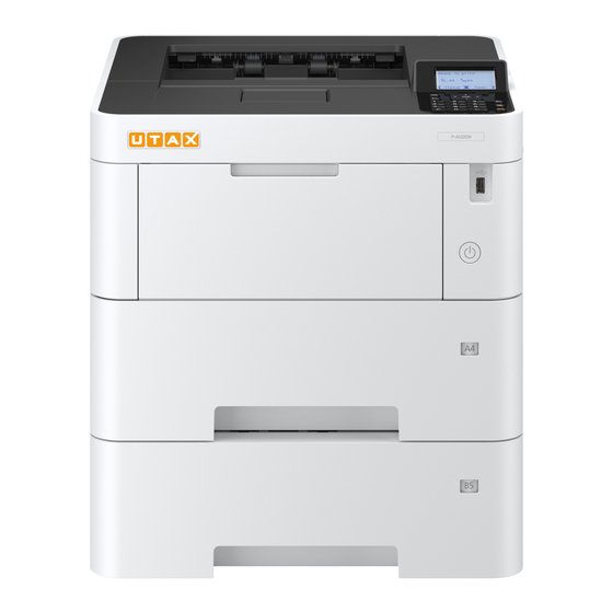
- Page 20 [CONFIDENTIAL] Specifications > Parts names 1 - 2 Parts names (1) Machine Exterior 1 Top Tray 6 USB Drive Slot 2 Paper Stopper 7 Operation Panel 3 Cassette 1 8 Anti-theft Lock Slot 4 Power Switch 9 Rear Cover 5 Handles...
- Page 21 [CONFIDENTIAL] Specifications > Parts names (2) Connectors/Interior 1 Option Interface 8 Multi Purpose Tray 2 USB Port 9 Paper Length Guide 3 USB Interface Connector 10 Paper Width Guides 4 Network Interface Connector 11 Bottom Plate 5 Fuser Cover 12 Size Dial 6 Paper Width Guides 13 Duplex Cover 7 Tray Extension...
- Page 22 [CONFIDENTIAL] Specifications > Parts names 14 Toner Container 17 Waste Toner Box cover 15 Toner Container Lock Lever 18 Waste Toner Box 16 Registration Roller (3) With Optional Equipments Attached 1 Cassette 2 5 Castor kit 2 Cassette 3 6 Bulk Paper Feeder 3 Cassette 4 7 Paper Stopper 4 Cassette 5...
- Page 23 [CONFIDENTIAL] Specifications > Parts names (4) Operation Panel Keys Select Key : Displays the Menu screen. Selects the menu displayed at the bottom of the message display. Increments or decrements numbers, or selects menu in the message display. In addition, moves the cursor when entering the characters. Finalizes a function or menu, Message display : and numbers that have been Displays the setting menu entered. and error messages. Returns to the previous display. Select Key : Selects the menu displayed at the bottom of the message display. Numeric keys. Enter numbers and symbols. Displays the Document Box screen. Exits the operation for the current user (i.e. log out). Cancels or pauses the job in ...
- Page 24 [CONFIDENTIAL] Specifications > Parts names (Option) 1 - 3 Parts names (Option) (1) PF-3110 1 Cassette 2 Paper size window 3 Interface connector 4 Pins (2) PF-3100 1-10...
- Page 25 [CONFIDENTIAL] Specifications > Parts names (Option) 1 Tray cover 2 Paper adjuster knob 3 Interface connector 4 Pins 5 Pins 1-11...
- Page 26 [CONFIDENTIAL] Specifications > Overview of Optional Equipment 1 - 4 Overview of Optional Equipment The following optional equipment is available for the machine. (1) Card Authentication Kit(B) (12) PF-3100 (11) IB-36 (2) PF3110 (10) PT-320 (3) CA-3100 ( ) Expansion Memory (5) SD Memory Card SDHC Memory Card Software option (6) HD-6/HD-7 (7) IB-50 (8) IB-51 (9) Parallel Interface (13)UG-33 Kit IB-32B (14) USB Keyboard...
- Page 27 [CONFIDENTIAL] Specifications > Overview of Optional Equipment (2) )PF-3110 "Paper Feeder (500-sheet x1)" Up to four additional cassettes identical to the machine's cassettes can be installed in the machine. Loading method are the same as the standard cassettes. (3) CA-3100 "Castor kit" If you are attaching Paper Feeder (500-sheet x1) to the printer and installing it on the floor, you can use the castor kit to maintain the machine's stability.
- Page 28 [CONFIDENTIAL] Specifications > Overview of Optional Equipment (14) USB Keyboard "USB Keyboard" A USB keyboard can be used to enter information into the text fields on the operation panel. A special mount is also available to install the keyboard on the machine. Please contact your dealer or service representative for information on keyboards that are compatible with your machine before you purchase one.
- Page 29 [CONFIDENTIAL] Installation > Environment 2Installation 2 - 1 Environment Installation environment Temperature: 50 to 90.5°F (10 to 32.5°C) (But humidity should be 70% or less when the temperature is 90.5°F (32.5°C).) Humidity: 10 to 80% (But the temperature should be 86°F (30°C) or less when humidity is 80%.) Power 45 ppm 50/55 ppm...
- Page 30 [CONFIDENTIAL] Installation > Installing the main unit 2 - 2 Installing the main unit Installation procedures (1) Unpacking and checking bundled items (2) Setup of a toner container (3) Installing the waste toner box (4) Connecting the cable (5) Loading Paper (6) Connecting the Power Cable (7) Power On (8) Default Setting...
- Page 31 [CONFIDENTIAL] Installation > Installing the main unit 1 Outer case 4 Bottom pad L 7 Upper pad R 10 Operation guide 2 Inner case 5 Machine cover 8 Upper pad L 11 Waste toner bottle 3 Bottom pad R 6 Machine 9 Top tray 12 Power cord Caution...
- Page 32 [CONFIDENTIAL] Installation > Installing the main unit Notes on main unit transportation Be sure to hold the both side handles at the lower part of the machine when carrying it, as shown in the figure. (2) Setup of a toner container Open the top cover (a) and pull the container lable (b) toward you to remove it.
- Page 33 [CONFIDENTIAL] Installation > Installing the main unit • Lift up the right side first to detach the toner container from the main unit. Shake the turned toner container 10 times or more as shown in the figure in order to distribute the toner evenly inside the container.
- Page 34 [CONFIDENTIAL] Installation > Installing the main unit Set the toner container (a) to the main unit and then rotate the toner container lock lever (b) to the lock position. Close the top cover (c). (3) Installing the waste toner box Open the waste toner box cover (a).
- Page 35 [CONFIDENTIAL] Installation > Installing the main unit (4) Connecting the cable (4-1)Connecting LAN Cable Important If the power is on, turn the power switch off. Connect the cable to the machine. Connect the network cable to the network interface connector located on the back side of the main unit. Connect the other end of the cable to the network router.
- Page 36 [CONFIDENTIAL] Installation > Installing the main unit (5) Loading Paper (5-1)Precaution for Loading Paper Before loading paper in the cassette, fan the paper taken from a new package to separate it in the procedures below. Fan the paper and align the edges at the flat place. In addition, note the following points.
- Page 37 [CONFIDENTIAL] Installation > Installing the main unit (5-2)Set paper in the cassette Pull the cassette completely out of the machine. Caution When pulling the cassette out of the machine, ensure it is supported and does not fall out. Adjust the cassette size. Adjust the position of the paper width guides located on the left and right sides of the cassette.
- Page 38 [CONFIDENTIAL] Installation > Installing the main unit Note If you are going to set paper that is longer than A4, pull out the extension cassettes pushing the lock button one by one and adjust them to the desired paper size. Turn the size dial so that the size of the paper you are going to use appears in the paper size window.
- Page 39 [CONFIDENTIAL] Installation > Installing the main unit Note • Load the paper with the print side facing down. • After removing new paper from its packaging, fan the paper before loading it in the cassette. • Before loading the paper, be sure that it is not curled or folded. Paper that is curled or folded may cause paper jams. •...
- Page 40 [CONFIDENTIAL] Installation > Installing the main unit Important Only use the power cable that comes with the machine. Note When the power is turned on for the first time, the toner installation operation is performed. (About 5 minutes) (7) Power On Turn the power switch (a) on.
- Page 41 [CONFIDENTIAL] Installation > Installing the main unit (8-1)Setting Date and Time Display the screen. [Menu] key > [▲] [▼] key > [Device Common] > [OK] key > [▲] [▼] key > [Date Setting] > [OK] key Configure the settings. [▲] [▼] key > [Time Zone] > [OK] key > Select the time zone > [OK] key > [▲] [▼] key > [Date] >...
- Page 42 [CONFIDENTIAL] Installation > Installing the main unit (8-2)Network Setup Configuring the Wired Network Note The machine is equipped with network interface, which is compatible with network protocols such as TCP/IP (IPv4), TCP/IP (IPv6), NetBEUI, and IPSec. It enables network printing on the Windows, Macintosh, UNIX and other platforms.
- Page 43 [CONFIDENTIAL] Installation > Installing the main unit Select the [OK] key. [▲] [▼] key > [Subnet Mask] > [OK] key Set the subnet mask. Note You can set any value between 000 and 255. Use the numeric keys or select the [▲] or [▼] key to enter a number. Select the [◄] or [►] key to move the position being entered, which is shown highlighted.
- Page 44 [CONFIDENTIAL] Installation > Installing the main unit (8-3)Specifying Paper Size and Media Type Note The default paper size setting for cassette 1, for the multi purpose tray, for the optional paper feeder (cassettes 2 to 5) and optional bulk feeder is "A4" or "Letter", and the default media type setting is "Plain". To change the type of paper to be used in cassettes, specify the paper size and media type setting.
- Page 45 [CONFIDENTIAL] Installation > Installing the main unit *2: 60/55/50 ppm model only *3: Appears when [Custom] is selected in Other Paper Size. 2-17...
- Page 46 [CONFIDENTIAL] Installation > Installing the main unit Paper Size and Media Type for the Cassettes: If the size dial is set to one of the sizes below, set the media type. "A4", "A5", "B5", "Letter", "Legal" or "A6" (Cassette 1 only) If the size dial is set to "Other", configure the settings for the paper size and the media type.
- Page 47 [CONFIDENTIAL] Installation > Installing the main unit Select [Normal], [1001 - 2000m], [2001 - 3000m] or [3001 - 3500m] using the cursor [▲][▼] keys. Press the [OK] key. The setting is set. (10) Printout the status page [Menu] key > [▲] [▼] key > [Report] > [OK] key >[▲] [▼] key > [Report] > [OK] key > [▲] [▼] key >[Status Page] >...
- Page 48 [CONFIDENTIAL] Installation > Installing the optional devices 2 - 3 Installing the optional devices (1) Unpacking and checking bundled items Take out the optional unit and accessories from the packing case. Remove the tape and cushioning materials for packing from the optional unit. (2) Optional unit installation Install necessary optional units in the main unit by referring to the installation procedures.
- Page 49 [CONFIDENTIAL] Installation > Installing the optional parts 2 - 4 Installing the optional parts Important Following procedures have to be done before PWB replacement. Otherwise PWB gets broken. • Unplug power code. • Press power switch for more than 1 second. (Remove electrical charge in main unit.) (1) Expansion memory The machine can perform more multiple jobs simultaneously by adding more memory.
- Page 50 [CONFIDENTIAL] Installation > Installing the optional parts Release the hook (b) and detach the interface cover (a) • Insert two of the hook (c) first to attach Remove 4 of screws (a) (M3x8) and the pin (b) and detach the main PWB unit (c) Attaching the expansion memory Turn the terminal section of the expansion memory (a) to the socket (b) side and align the cut-out to the projection of the soket to insert it straight in angle.
- Page 51 [CONFIDENTIAL] Installation > Installing the optional parts Note Removing the Memory Module To remove the memory module, remove the right cover and the memory slot cover from the main unit. Then, carefully push the two stoppers so that the memory module pops up from the socket. Verifying the Memory Module To verify that the memory module is working properly, print out a status page and check its content.
- Page 52 [CONFIDENTIAL] Installation > Installing the optional parts Reattach the slot cover (b) once detached to the main unit with two screws (a) Insert the power cord into the socket and turn on the power switch. Format SD Card To use an unused SD/SDHC memory card, you must first use the machine to format the SD/SDHC memory card. Important •...
- Page 53 [CONFIDENTIAL] Installation > Installing the optional parts (3) SSD (HD-6/HD-7) Turn off the main unit and disconnect the power cord and all interface cables. Note The shutdown confirmation screen is displayed. It might take about three minutes to shut down. Remove two screws (b) and the option slot cover (a).
- Page 54 [CONFIDENTIAL] Installation > Installing the optional parts Note The factory default login user name and login password are set as shown below. • 45 ppm model: Login User Name/ Login Password: 4500 / 4500 • 50 ppm model: Login User Name/ Login Password: 5000 / 5000 •...
- Page 55 [CONFIDENTIAL] Installation > Installing the optional parts (3-1)Wireless Network Interface Kit (IB-36) Turn off the main unit and disconnect the power cord and all interface cables. Note The shutdown confirmation screen is displayed. It might take about three minutes to shut down. Attaching the Wi-Fi unit 45 ppm model After twisting the Wi-Fi cover (a), remove it.
- Page 56 [CONFIDENTIAL] Installation > Installing the optional parts Important Take care not to twist the WiFi PWB assembly in the vertical direction in order to avoid the damage when attaching and detaching it. Reattach the Wi-Fi cover (a) in the original position. (4) ID card reader ID card reader installation requires the following parts.
- Page 57 [CONFIDENTIAL] Installation > Installing the optional parts Connect the USB connector (c) to the printer. • A:75 mm or more 50/55/60 ppm model 45 ppm model 2-29...
- Page 58 [CONFIDENTIAL] Installation > Optional Function 2 - 5 Optional Function Application Data Encryption (Data Encryption/Overwrite) UG-33 (ThinPrint Option) ID Card (Card Authentication Kit) *1: This can be used on a trial basis for a limited time. Note • Restrictions such as the number of times the application can be used during the trial period differ depending on the application.
- Page 59 [CONFIDENTIAL] Machine Design > Mechanical Configuration 3Machine Design 3 - 1 Mechanical Configuration (1) 60/55/50 ppm model 10 11 Light path Paper path Paper path (option) 1 Cassette 10 Drum unit 2 Cassette paper feed section 11 Transfer/Separation section 3 Paper feed conveying section 12 Eject tray (facedown) 4 MP tray 13 Eject section...
- Page 60 [CONFIDENTIAL] Machine Design > Mechanical Configuration (2) 45 ppm model 10 11 Light path Paper path Paper path (option) 1 Cassette 9 Charger roller unit 2 Cassette paper feed section 10 Drum unit 3 Paper feed conveying section 11 Transfer/Separation section 4 MP tray 12 Eject tray (facedown) 5 MP tray paper feed section...
- Page 61 [CONFIDENTIAL] Machine Design > Extension device construction (option) 3 - 2 Extension device construction (option) (1) 500-sheet x1 Paper Feeder cross-section view (PF-3110) Paper path (option) 1 Cassette paper feed section (Cassette 2 to 5) (2) 2000-sheet x1 Paper Feeder cross-section view (PF-3100) Paper path (option) 1 Cassette paper feed section (Cassette 2)
- Page 62 [CONFIDENTIAL] Machine Design > Electric parts 3 - 3 Electric parts (1) Electric parts layout 1 Engine PWB 5 Power source fan motor 2 Low voltage PWB 6 LSU fan motor 3 Main motor 7 Developer fan motor 4 Drum motor *1 *1: 60/55/50 ppm model only...
- Page 63 [CONFIDENTIAL] Machine Design > Electric parts (2) Descriptions about the major PWBs (2-1)Main PWB Controls the software such as the print data processing and provides the interface with computers. (2-2)Engine PWB Controls printer hardware such as high voltage/bias output control, paper conveying system control, and fuser temperature control, etc.
- Page 64 [CONFIDENTIAL] Machine Design > Electric parts (2-3)Power source PWB After full-wave rectification of AC power source input, switching for converting to 24 V DC for output. Controls the fuser heater. (2-4)High voltage PWB Generates main charging, developing bias, transfer bias.
- Page 65 [CONFIDENTIAL] Machine Design > Electric parts (2-5)Operation PWB Consists the LCD, LED indicators and key switches. (3) PWBs (3-1)Layout Laser scanner unit Drum unit...
- Page 66 [CONFIDENTIAL] Machine Design > Electric parts 1 Main PWB Controls the software such as the print data processing and provides the interface with computers. 2 Engine PWB Controls printer hardware such as high voltage/bias output control, paper conveying system control, and fuser temperature control, etc. 3 Power source PWB After full-wave rectification of AC power source input, switching for converting to 24 V DC for output.
- Page 67 [CONFIDENTIAL] Machine Design > Electric parts (3-2)Part name table (PWB) Name used in service manual Name used in parts list Part. No. Main PWB PARTS PWB ASSY MAIN SP 302TP9408_*1,*2 PARTS PWB ASSY MAIN SP EU 302TP9407_*3 Engine PWB PARTS PWB ASSY ENGINE SP 302TT9403_*5 PARTS PWB ASSY ENGINE SP 302TS9401_*6...
- Page 68 [CONFIDENTIAL] Machine Design > Electric parts (4) Sensors and Switches (4-1)Layout Fuser unit Developer unit Drum unit High-voltage PWB 1 Paper sensor 1 Detects the presence of paper in the cassette. 2 Paper sensor 2 Detects the presence of paper in the cassette. 3 Cassette size switch Detects the paper size dial setting of the paper setting dial.
- Page 69 [CONFIDENTIAL] Machine Design > Electric parts 18 Rear cover switch Detects the opening and closing of the rear cover. 19 Waste toner sensor Detects when the waste toner box is full. 20 Power source switch Change ON/OFF the power supply of a main PWB, an operation PWB, etc.
- Page 70 [CONFIDENTIAL] Machine Design > Electric parts Name used in service manual Name used in parts list Part. No. Eject sensor (FK-3201) (302V393050)*5,*1 (FK-3202) (302V393060)*5,*2 (FK-3200) (302V393040)*5,*3,*4 (FK-3301) (302TP93020*9,*1 (FK-3302) (302TA93050)*9,*2 (FK-3300) (302TA93040*9,*3,*4 Fuser pressure release sensor PARTS SENSOR OPT SP 303M89426_ Fuser thermistor 1 (FK-3201)
- Page 71 [CONFIDENTIAL] Machine Design > Electric parts (5) Motors (5-1)Layout Laser scanner unit Drum unit 1 Main motor Drives the paper feed section and conveying section. 2 Drum motor *1 Drives the drum unit and transfer roller. 3 Eject motor Drives the eject section. 4 Polygon motor Drives the polygon mirror.
- Page 72 [CONFIDENTIAL] Machine Design > Electric parts (5-2)Part name table (motor) Name used in service manual Name used in parts list Part. No. Main motor PARTS MOTOR-BL W30 SP 302K39420_ Drum motor PARTS MOTOR-BL W30 SP 302K39420_ Eject motor PARTS MOTOR EJECT SP 302T99405_ Polygon motor (LK-3170)
- Page 73 [CONFIDENTIAL] Machine Design > Electric parts (6) Other parts (6-1)Layout Fuser unit Drum unit Developer drive unit Feed drive unit 1 Paper feed clutch Primary paper feed from cassette. 2 Registration clutch Controls the secondary paper feed. 3 Developer clutch Controls the drive of the developer.
- Page 74 [CONFIDENTIAL] Machine Design > Electric parts (6-2)Part name table (Other parts) Name used in service manual Name used in parts list Part. No. Paper feed clutch PARTS CLUTCH 20-2W Z35R 302LV9416_ (PARTS DRIVE FEED ASSY SP) (302LV9425_) Registration clutch CLUTCH 50 Z35R 302KV4404_ Developer clutch CLUTCH 50 Z35R...
- Page 75 [CONFIDENTIAL] Machine Design > Electric parts Name used in service manual Name used in parts list Part. No. Fuser thermostat 2 (FK-3201) (302V393050)*5,*1 (FK-3202) (302V393060)*5,*2 (FK-3200) (302V393040)*5,*3,*4 (FK-3301) (302TP93020*9,*1 (FK-3302) (302TA93050)*9,*2 (FK-3300) (302TA93040*9,*3,*4 Drum heater*2 (DK-3171(J)) (302T99308_)*5,*1 (DK-3172(U)) (302T99307_)*5,*2 (DK-3170(E)) (302T99306_)*5,*3 (DK-3174(AO)) (302T99309_)*5,*4...
- Page 76 [CONFIDENTIAL] Machine Design > Electric parts (Optional unit) 3 - 4 Electric parts (Optional unit) (1) Paper feeder (PF-3110) (1-1)Layout 8 10 1 PF PWB Controls electrical components in the paper feeder and communications with the printer. 2 PF paper sensor 1 Detects the paper remaining amount level.
- Page 77 [CONFIDENTIAL] Machine Design > Electric parts (Optional unit) (1-2)Part name table Name used in service manual Name used in parts list Part. No. PF PWB PARTS PWB ASSY PF MAIN SP 303NY9401_ PF paper sensor 1 (PARTS PWB ASSY PF MAIN SP) (303NY9401_) PF paper sensor 2 (PARTS PWB ASSY PF MAIN SP)
- Page 78 [CONFIDENTIAL] Machine Design > Electric parts (Optional unit) 1 PF PWB Controls electrical components in the bulk paper feeder and communications with the printer. 2 PF tray top position sensor This sensor, when the top of the paper stack in the paper tray has reached the top most position, ready for feeding paper through the bulk paper feeder output slot.
- Page 79 [CONFIDENTIAL] Machine Design > Electric parts (Optional unit) (2-2)Part name table Name used in service manual Name used in parts list Part. No. PF PWB PARTS PWB PF MAIN ASSY SP 303S39403_ PF tray top position sensor PARTS SENSOR OPT. SP 302P79401_ PF paper feed sensor PARTS SENSOR OPT.
- Page 80 [CONFIDENTIAL] Machine Design > Drive system 3 - 5 Drive system (1) Drive configuration Entire drive 60/55/50 ppm model Eject motor Drum Upper eject Cleaning roller Charger roller roller Developer roller Drum motor Lower eject Registration roller roller Heat roller Middle feed roller Faceup roller DU conveying...
- Page 81 [CONFIDENTIAL] Machine Design > Drive system 45 ppm model Drum Eject motor Charger roller Upper eject roller Developer roller Cleaning roller Lower eject Registration roller roller Heat roller Middle feed roller DU conveying DU conveying roller roller Paper feed roller Eject roller Transfer roller Main motor...
- Page 82 [CONFIDENTIAL] Machine Design > Mechanical construction 3 - 6 Mechanical construction (1) Paper feed section Paper feed/conveying section consists of the paper feed unit that feeds paper from the cassette and the MP tray paper feed unit that feeds paper from the MP tray. (1-1)Cassette paper feed section The cassette can contain 500 sheets (80 g/m2).
- Page 83 [CONFIDENTIAL] Machine Design > Mechanical construction Block diagram Engine PWB PAPER SEN1N YC19-11 High voltage PWB PAPER SEN2N YC19-10 LSENS YC14-3 Lift sensor MMOTCW YC4-1 MMOTRDYN YC4-2 MMOTCLKN Main motor YC4-3 MMOTONN YC4-4 LIFTMOTOR YC13-1 Lift motor FEEDCLN YC5-4 Paper feed clutch CAS3 YC7-1 CAS2...
- Page 84 [CONFIDENTIAL] Machine Design > Mechanical construction (1-2)MP tray paper feed section The MP tray can contain 100 sheets. Feeding from the MP tray is performed by the rotation of the MP paper feed roller. Also, function of the MP separation pad prevents paper from multiple feeding. 1 MP paper feed roller 3 MP bottom plate 5 MP base...
- Page 85 [CONFIDENTIAL] Machine Design > Mechanical construction (2) Conveying section The conveying section conveys paper to the transfer/separation section as paper feeding from the cassette or MP tray, or as paper refeeding for duplex printing. Paper by feeding is conveyed by the paper feed roller to the position where the registration sensor is turned on, and then sent to the transfer/separation section by the upper registration roller and lower registration roller.
- Page 86 [CONFIDENTIAL] Machine Design > Mechanical construction Block diagram Engine PWB Registration sensor 1 *1 REGSENSN YC19-12 Drum relay PWB Registration sensor 3 *2 Drum PWB REGSEN2 YC6-2 Relay-L PWB Registration sensor 2 *2 REGSEN2 YC3-10 YC2-21 Drum relay PWB MMOTCW YC4-1 MMOTRDYN YC4-2...
- Page 87 [CONFIDENTIAL] Machine Design > Mechanical construction 1 Drum 3 Charger cleaning roller 2 Charger roller 4 Charger case Block diagram Engine PWB EECLK YC2-1 Relay-L PWB Drum relay PWB Drum PWB EESIO YC2-3 MHVCLK YC19-4 Main charger roller MACCNT YC19-5 High voltage PWB MDCCNT YC19-6...
- Page 88 [CONFIDENTIAL] Machine Design > Mechanical construction (3-2)Cleaning unit In the cleaning section, toner remaining on the drum surface after transferring is removed by the cleaning blade, and collected to the waste toner box by the drum screw. The cleaning lamp consists of the LED lamp, and it removes the electric charge remaining on the drum before the main charge Drum 1 Cleaning blade...
- Page 89 [CONFIDENTIAL] Machine Design > Mechanical construction (4) Developer section The developer unit consists of the developer roller that forms the toner layer, the developer blade and the developer screws that agitate the toner.Also, the toner sensor checks whether or not toner remains in the developer unit. Drum 1 Developer roller 4 Developer screw A...
- Page 90 [CONFIDENTIAL] Machine Design > Mechanical construction Block diagram Engine PWB Drum PWB EECLK YC2-1 1WIRE EESIO YC2-1 Container relay PWB YC2-3 TSENS Relay-L PWB YC2-6 TMOT TSENS YC2-15 YC3-2 Toner sensor TMOT YC4-1 Toner motor Drum relay PWB HVCLK YC19-7 Developer bias BDCNT YC19-8 High voltage PWB...
- Page 91 [CONFIDENTIAL] Machine Design > Mechanical construction 1 Polygon motor 3 Direction change mirrer 5 LSU base 2 fθ main lens 4 LSU dust shield glass Block diagram Engine PWB Polygon motor PLGDRN YC15-3 PLGRDYN YC15-4 POLCLK YC15-5 Laser light VDATA1P YC16-2 Laser Photo...
- Page 92 [CONFIDENTIAL] Machine Design > Mechanical construction 1 Transfer roller 3 Separation needle 2 Paper chute guide 4 Drum Block diagram Engine PW Separation bias SCNT YC19-15 TRREM YC19-16 High voltage PWB TCNT Transfer bias YC19-17 Transfer roller (7) Fuser section The paper sent from the transfer/separation section is interleaved between the heat roller and the press roller. The heat roller is heated by the fuser heater, and the toner is fused by heat and pressure and fixed onto the paper because the press roller is pressed by the fuser press spring.
- Page 93 [CONFIDENTIAL] Machine Design > Mechanical construction 1 Heat roller 5 Separators 9 Fuser eject pulley 2 Fuser heater 6 Press roller 10 Fuser thermistor 2 3 Fuser thermostat 7 Actuater (Eject sensor) 11 Pre fuser guide 4 Fuser thermistor 1 8 Fuser eject roller Block diagram Power source...
- Page 94 [CONFIDENTIAL] Machine Design > Mechanical construction (45 ppm model) (60/55/50 ppm model) 1 Upper eject roller 6 Vertical guide 11 Faceup roller *1 2 Upper eject pulley 7 Paper exit guide 12 Faceup pulley *1 3 Actuator (Eject full sensor (EFS)) 8 Top cover 13 Feedshift guide *1 4 Lower eject roller...
- Page 95 [CONFIDENTIAL] Machine Design > Mechanical construction Block diagram Engine PWB Engine PWB PAPFULN PAPFULN Eject full sensor YC12-3 YC12-3 Eject full sensor EXITSENSN EXITSENSN YC26-3 YC26-3 Eject sensor Eject sensor Relay-L PWB Relay-L PWB OUTB3 OUTB3 YC12-1 YC12-1 OUTB1 OUTB1 YC12-2 YC12-2 OUTA3...
- Page 96 [CONFIDENTIAL] Machine Design > Mechanical construction 1 DU conveying roller 4 Actuater (Duplex sensor 2) 7 Upper feed guide 2 DU conveying pulley 5 DU base 3 Actuater (Duplex sensor 1) *1 6 DU lower guide *1: 60/55/50 ppm model Block diagram Engine PWB Relay-L PWB...
- Page 97 [CONFIDENTIAL] Machine Design > Mechanical construction (option) 3 - 7 Mechanical construction (option) (1) Paper feeder (PF-3110) The paper feeder conveys paper from the cassette to the printer. Cassette can hold up to 500 sheets of paper. Paper is fed from the paper feeder by the rotation of the pickup roller and paper feed roller. The retard roller prevents multiple sheets from being fed at one time, via the torque limiter.
- Page 98 [CONFIDENTIAL] Machine Design > Mechanical construction (option) Block diagram PF PWB PF conveying sensor YC1-3 TMDIR YC6-1 TMLOCK YC6-2 PF feed motor TMCLK YC6-3 TMDRVN YC6-4 FEEDCLN YC8-2 PF conveying clutch TRANSCLN YC8-4 PF feed clutch PAPSIZ0 YC2-1 PAPSIZ1 YC2-2 PF cassette size switch PAPSIZ2 YC2-4...
- Page 99 [CONFIDENTIAL] Machine Design > Mechanical construction (option) 1 PF paper feed roller 3 PF retard roller 5 PF friction pad 2 PF pickup roller 4 PF lift plate Block diagram YC3-1 YC3-2 PF paper feed motor YC3-3 YC3-4 UPLIMIT PF tray top position sensor YC5-3 FEEDN YC2-3...
- Page 100 [CONFIDENTIAL] Maintenance > Important Notes of Maintenance 4Maintenance 4 - 1 Important Notes of Maintenance (1) Precautions Before starting disassembly, push the power switch to shutdown. And check the operation panel display disappears certainly. Then, unplug the power cable from the wall outlet. Do not touch a parts on the board just after turn off or unplug, since electric charge may remain in a capacitor on power supply board.
- Page 101 Maintenance > Maintenance Parts 4 - 2 Maintenance Parts (1) Maintenance Kit [60/55/50ppm] Service manual Name in Parts list Parts number MK-3301 MK-3301/MAINTENANCE KIT 1702TA9JP0 *1 MK-3300 MK-3300/MAINTENANCE KIT 1702TA8NL0 *2 MK-3302 MK-3302/MAINTENANCE KIT 1702TA7US0 *3 MK-3304 MK-3304/MAINTENANCE KIT 1702TA8AS0 *4 (500,000 images) Transfer roller ROLLER TRANSFER ASSY...
- Page 102 Maintenance > Maintenance Parts replacement procedure 4 - 3 Maintenance Parts replacement procedure Maintenance Kit has to be replaced every 300,000 images (45 ppm) and 500,000 images (50/55/50 ppm). [Replace Maintenance kit] comes up on display when the time for replacement. Replace the Maintenance Kit with following procedures.
- Page 103 Maintenance > Maintenance Parts replacement procedure (1-2)Detaching and refitting the retard roller Release two hooks (b) in backside of cassette (a) and then detach the retard roller assembly (c). Remove spring (a). Remove the retard roller holder (b) by rotating it. Check or replace the retard roller and refit all the removed parts.
- Page 104 Maintenance > Maintenance Parts replacement procedure Detach the left upper cover. Remove the fulcrum (b) of left side by extending the cover (a). Twisting the cover (a) and remove the fulcrum (c) of right side. Pull the front cover (a) frontward. Remove the MP paper feed unit (a).
- Page 105 Maintenance > Maintenance Parts replacement procedure Detaching and refitting the paper feed roller Release the lock lever (a) and then slide the MP paper feed roller shaft (b). Detach the MP paper feed roller (c). Check or replace the paper feed roller and refit all the removed parts. Important Pay attention not to touch on surface in the new MP feed roller replacement. ...
- Page 106 Maintenance > Maintenance Parts replacement procedure Remove toner container guide (e) Open the front cover (b). Pull the imaging unit (c) out. Release the hook (d) and then remove the container guide (e) by sliding it. Detaching and refitting the developer unit (a) Pull the connector (b) out.
- Page 107 Maintenance > Maintenance Parts replacement procedure Important • Keep the unit and main unit flat when move them and do not get them vibration or impact. • Do not store or transport them with tilted position. (4) Drum section (4-1)Detaching and refitting the drum unit Detach the developer unit.
- Page 108 Maintenance > Maintenance Parts replacement procedure Important When placing the drum unit on the table, do not deform the star-wheels (b). (4-2)Detaching and refitting the main charger roller unit Release the lock lever (a) and then detach the main charger roller unit (b) from the drum unit (c). Check or replace the main charger roller unit (b) and refit all the removed parts.
- Page 109 Maintenance > Maintenance Parts replacement procedure Detach the transfer roller. Detach the shaft of transfer roller (a) from each bushes (b). Detach the transfer roller assembly (a) upward. Check or replace the transfer roller assembly and refit all the removed parts. (5-2)Detaching and refitting the separation needle unit Detach the transfer roller.
- Page 110 Maintenance > Maintenance Parts replacement procedure Important Check if the parts is fixed at the time of attachment. (6) Fuser section (6-1)Detaching and refitting the fuser unit Detach the inlet cover and interface cover (See Page 4-14) Detach the rear cover. (See Page 4-21)
- Page 111 Maintenance > Maintenance Parts replacement procedure Rotate the connector cover B (a) and release the hook (b) and remove the cover. Pull two connectors (c) out. Remove the screw (a) and then detach the fuser unit (b) frontward. Check or replace the fuser unit and refit all the removed parts. Important •...
- Page 112 Maintenance > Assembly and disassembly 4 - 4 Assembly and disassembly (1) Outer covers (1-1)Detaching and refitting the inlet cover and interface cover Open the rear cover (a). Release hook (b) and detach the interface cover (a). • Attach 2 hooks (c) first when putting it back. Remove screw (a) and detach the inlet cover (b).
- Page 113 Maintenance > Assembly and disassembly (1-2)Detaching and refitting the right cover Pull out the cassette (a). Slide and remove Wi-Fi cover (a). Open the top cover (a). 4-15...
- Page 114 Maintenance > Assembly and disassembly Open the front cover (a). Open the rear cover (a). Release hook (b) and detach the interface cover (a). • Attach 2 hooks (c) first when putting it back. 4-16...
- Page 115 Maintenance > Assembly and disassembly Remove screw (a) and detach the inlet cover (b). (M3x8) Remove the right cover (a). Remove 3 screws (a) (M3x8) and (b) (M3x12). Release hook (c). Release 3 hooks (d). Hold up the right cover and release 4 hooks (e) then remove the cover. 4-17...
- Page 116 Maintenance > Assembly and disassembly (1-3)Detaching and refitting the rear left and left cover Open the rear cover (a). Detach the rear left cover (a). Pull the cover and release hook (b). Detach the rear left cover (a) by rotating it. Open the top cover (a).
- Page 117 Maintenance > Assembly and disassembly Pull out the cassette (a). Open the front cover (a). Detach the left cover. Remove screw (a) for the lower left cover. (M3x8) Release two hooks (c). Release 2 hooks (d). Hold up the left cover and release 4 hooks (e) then remove the cover. 4-19...
- Page 118 Maintenance > Assembly and disassembly 4-20...
- Page 119 Maintenance > Assembly and disassembly (1-4)Detaching and refitting the top cover Remove the right cover. (See Page 4-15 Detach the left cover. (See Page 4-18 Detach the top cover assembly. Remove two screws (b). (M3x8) Release two hooks (c) and lift the top cover upward. Pull out FFC (d) from the connector (e) and then remove the top cover assembly (f).
- Page 120 Maintenance > Assembly and disassembly 50/55/60ppm model only Remove the screw (a) and the grounding wire (b). (M3x8) Open the connector cover (c) and then remove three connectors (d). 4-22...
- Page 121 Maintenance > Assembly and disassembly Remove the shaft (b) by sliding the rear cover (a) and then detach the rear cover assembly (c). (2) Optical section (2-1)Detaching and refitting the laser scanner unit Detach the top cover assembly. (See Page 4-21) Remove laser scanner unit.
- Page 122 Maintenance > Assembly and disassembly Important • Wear anti-static wrist band to avoid from static shock on the laser scanner unit. Do not touch APC PWB and terminal of FCC. • Pay attention to insert FCC completely when connect it. If miss the connection, error comes up and takes time to fix it.
- Page 123 Maintenance > Assembly and disassembly [60/55/50ppm] 45 ppm (4) PWBs Caution Before replacing the PWB, be sure to take the following procedures. Otherwise, The PWB may get damaged. Disconnect the power cord. Press the power switch one second or more. (discharge the electric charge inside the main unit) 4-25...
- Page 124 Maintenance > Assembly and disassembly (4-1)Detaching and refitting the main PWB Open the rear cover (a). Release hook (b) and detach the interface cover (a). • Attach 2 hooks (c) first when putting it back. Unplug the power cable. Detach the main PWB. Remove four screws (a) and (b) then detach the main PWB unit (c).
- Page 125 Maintenance > Assembly and disassembly Important Re-activate the license if optional licensed product is installed. 1) Card Authentication Kit(B) 2) UG-33 (ThinPrint) Re-input four-digit encrypted code that was input at setup. Reset the user initial values from the System Menu and Command Center. 4-27...
- Page 126 Maintenance > Assembly and disassembly (4-2)Detaching and refitting the engine PWB Remove the right cover. (See Page 4-15 Detach the left cover. (See Page 4-18 Detach the top cover assembly. (See Page 4-21 Detach the wire guide 1. Remove two FFCs (a) from inside of frame. Release the wires (c) and FFC (d) from hooks (b).
- Page 127 Maintenance > Assembly and disassembly Detach the engine PWB. Pull all connectors out from engine PWB (a). Remove four screws (b) and then detach the engine PWB (a). (M3x8) Check or replace the engine PWB and refit all the removed parts. 4-29...
- Page 128 Maintenance > Assembly and disassembly Important When replacing the engine PWB (a), remove the EEPROM (U21) from the PWB and then reattach it to the new PWB. When replacing the engine PWB, make sure to check the barcode label of the engine PWB and attach correct one.
- Page 129 Maintenance > Assembly and disassembly (4-3)Detaching and refitting the relay-L PWB Detach the top cover assembly. (See Page 4-21) Detach the LSU fan motor. Pull the connectors (a) out from relay-L PWB and then release the wires (c) from hooks (b). Detach the LSU fan motor assembly (d) upward.
- Page 130 Maintenance > Assembly and disassembly (4-4)Detaching and refitting the power source PWB Caution Before replacing the PWB, be sure to take the following procedures. Otherwise, The PWB may get damaged. Disconnect the power cord. Press the power switch one second or more. (discharge the electric charge inside the main unit) Remove the right cover.
- Page 131 Maintenance > Assembly and disassembly 4-33...
- Page 132 Maintenance > Assembly and disassembly (4-5)Detach the high-voltage PWB. Detach the cassette. Remove the right cover. (See Page 4-15 Detach the left cover. (See Page 4-18 Detach the power supply fan motor. (See Page 4-40 Detach the power supply PWB. (See Page 4-32 Place the main unit front side up.
- Page 133 Maintenance > Assembly and disassembly Detach the duplex unit. Remove 7 screws (a). (M3x8) Push the joint section (b) and pull out the feed roller (c). Detach the duplex unit frontward. Detach the high voltage PWB. Remove 1 screw (a). (M3x8) Pull two connectors (b) out and then detach the high voltage PWB (c).
- Page 134 Maintenance > Assembly and disassembly 4-36...
- Page 135 Maintenance > Assembly and disassembly (4-6)Detaching and reattaching the operation PWB Open the top cover (a). Remove the jam clearance procedure sheet (b). Remove 2 screws (c). (M3x8) Remove the operation PWB. Rotate the operation PWB cover (a). Remove the screw (b) and take the operation PWB out. (M3x8) Check or replace the operation PWB and refit all the removed parts.
- Page 136 Maintenance > Assembly and disassembly Detach the top cover assembly. (See Page 4-21 Detach the main PWB. (See Page 4-26 Detach the wire guide 1. (See Page 4-26 Detach the controller box cover. (See Page 4-32 Detaching main drive unit Pull the connector (a) out from the motor and then release the wires (b) from wire holder (c).
- Page 137 Maintenance > Assembly and disassembly (5-2)Detaching and refitting the paper feed drive unit Remove the right cover. (See Page 4-15 Remove the paper feed drive unit. Pull the connector (a) out. Remove 2 screws (b) and then detach the paper feed drive unit (c). Check or replace the paper feed drive unit and refit all the removed parts.
- Page 138 Maintenance > Assembly and disassembly (5-4)Detaching and reattaching the power source fan motor Remove the right cover. (See Page 4-15 Detach the power source fan motor. Pull the connector (b) of the power source fan motor (a). Release three hooks (c) using flat-blade screwdriver (d) and then detach the power source fan motor (a). Check or replace the power source fan motor and refit all the removed parts.
- Page 139 Maintenance > Assembly and disassembly Disconnect connector (d) of the fan motor wire (c). Detach the rear fan motor (e). Check or replace the rear fan motor and refit all the removed parts. 4-41...
- Page 140 Maintenance > Assembly and disassembly (5-6)Direction of the fan motor installation. When detaching or refitting the fan motor, pay attention of the airflow direction (intake or exhaust). • Center motor fan (a) *1: Exhaust (Rating label face down) • Power source fan motor (b): Intake (Rating label face inside) •...
- Page 141 Maintenance > Assembly and disassembly (Optional items) 4 - 5 Assembly and disassembly (Optional items) (1) Paper feeder (PF-3110) (1-1)Detaching and refitting the paper feed roller Remove cassette (a) from paper feeder (b). Remove the paper feed roller unit. Press the lock lever (a) and slide the roller holder (b). Detach the paper feed roller assembly (c).
- Page 142 Maintenance > Assembly and disassembly (Optional items) (1-2)Detaching and refitting the retard roller Remove cassette (a) from paper feeder (b). Release two hooks (b) in backside of cassette (a) and then detach the retard roller assembly (c). Remove the retard roller. Remove spring (a).
- Page 143 Maintenance > Assembly and disassembly (Optional items) (1-3)Detaching and refitting the drive unit and PF PWB. Detach the top cover. Remove 5 screws (a). (M3x8) Lift up rear edge if the top cover (b). Pull out cassette size switch (c) and remove top cover (b). Detach the PWB cover.
- Page 144 Maintenance > Assembly and disassembly (Optional items) Remove the drive unit. Pull the 3 connectors (a) out and release the wires (b) from wire holder (c). Remove three screws (d) and detach the drive unit (e). (M3x8) Detach the PF PWB cover. Raise the feed roller assembly (a) up.
- Page 145 Maintenance > Assembly and disassembly (Optional items) (2) Paper feeder (PF-3100) (2-1)Remove the bulk feeder Take away the bulk feeder (b) from main unit by sliding on the mount rails (a). Hold up the bulk feeder (b). (2-2)Detach the tray cover. •...
- Page 146 Maintenance > Assembly and disassembly (Optional items) 4-48...
- Page 147 Maintenance > Assembly and disassembly (Optional items) (2-3)Detach the side cover. • Do this in case if access to parts inside. Remove two screws (a) on lower side and detach the right/left side covers (b). (2-4)Remove paper feed section and top cover •...
- Page 148 Maintenance > Assembly and disassembly (Optional items) 4-50...
- Page 149 [CONFIDENTIAL] Firmware > Firmware update 5Firmware 5 - 1 Firmware update Execute the following to update the firmware below. • The processing time is reduced with simultaneous processing by group. [GROUP1 UPDATE] UPDATE Target Master file name Message step Controller Package DL_PKG_CTRL.2TP CPKG Product Line Platform...
- Page 150 [CONFIDENTIAL] Firmware > Firmware update Verify the signature at firmware update Verify the signature of the update file to prevent the firmware update with illegally falsified data. File names of the signature and firmware certificate Target Signature file name Firmware certificate file name Product Line Platform 2TP_CTRL_PLP_sign.bin 2TP_CTRL_PLP_cert.pem...
- Page 151 [CONFIDENTIAL] Firmware > Firmware update Preparations Unzip the file containing the downloaded firmware and then copy the firmware and high-speed master file (skip files: ES_SKIP.ON) in the root folder of the USB memory. • If the high-speed master file exists, the same version firmware update is skipped. Turn ON the power switch (a) and confirm if the screen shows “Ready to print”...
- Page 152 [CONFIDENTIAL] Firmware > Firmware update • When [Completed] is displayed, the firmware update is completed. • Check if the new firmware versions are displayed. F W - U p d a t e 1 / 2 3 C o m p l e t e d [ P L P ] 2 / 2 3 2 T X .
- Page 153 [CONFIDENTIAL] Firmware > Firmware update • In case of occurring an error during the firmware update, the process is immediately interrupted and the error message and error code are displayed. Codes Description Codes Description 0000 Others S000 Other signature verification error *1 There is no master file.
- Page 154 [CONFIDENTIAL] Service mode > Executing a service mode Service mode The machine is equipped with a maintenance function which can be used to maintain and service the machine. 6 - 1 Executing a service mode [Message Display] Ready to copy 1.
- Page 155 [CONFIDENTIAL] Service mode > Service settings 6 - 2 Service settings Items Contents Page Service Status Outputs the service status page. Page 6-3 Network Status Outputs the network status page. Page 6-10 OP Network Status Outputs the option network status page. Page 6-10 Test Page The test page is printed with halftones.
- Page 156 [CONFIDENTIAL] Service mode > Service settings Service Status Contents Prints a status page for service purpose. The status page includes various settings and service cumulative. Purpose To acquire the current printing environmental parameters and cumulative information. Method Enter the Service Setting menu. Select [Status Page] using the [▲][▼]...
- Page 157 [CONFIDENTIAL] Service mode > Service settings Detail of service status page (1) Service Status Page Z468Z00040 Printer 2019/01/08 14:30 ECOSYS P3160dn Firmware Version 2TP_S000.003.010 2018.11.29 (4)(5)(6) [2V2_1000.003.002] [2T6_1100.001.001] [2TA_7000.001.001] Controller Information Memory Status Standard Size 512MB Override A4/LT Option Slot 0 MB Host Buffer Size Rate Total Size...
- Page 158 [CONFIDENTIAL] Service mode > Service settings Detail of service status page (2) Service Status Page Z468Z00040 Printer 2019/01/08 14:30 ECOSYS P3160dn Firmware Version 2TP_S000.003.010 2018.11.29 [2V2_1000.003.002] [2T6_1100.001.001] [2TA_7000.001.001] Controller Information Engine Information (36) NVRAM Version _Cb26630_Cb26630 (32) Altitude Adjustment (37) MAC Address 00:17:C8:16:84:04 Status...
- Page 159 [CONFIDENTIAL] Service mode > Service settings Description Supplement Firmware version Machine serial number System date Engine soft version Engine boot version Operation panel mask version Total memory size Local time zone Report output date Day/Month/Year hour: minute (10) NTP server name (11) Presence or absence of the optional Installed/Not Installed...
- Page 160 [CONFIDENTIAL] Service mode > Service settings Description Supplement (28) RP Code Code the engine software version and the date of update. (29) Code the main software version and the date of update. (30) Code the engine software version and the date of the previ- ous update.
- Page 161 [CONFIDENTIAL] Service mode > Service settings Description Supplement (48) USB information U00: Not Connected U01: Full speed U02: Hi speed (49) Paper handling information 0: Paper source unit select/1: Paper source unit (50) Auto cassette change 0: OFF/ 1: ON (51) Color printing double count mode 0: All single counts...
- Page 162 [CONFIDENTIAL] Service mode > Service settings Description Supplement (67) RFID information (68) Toner install mode information (69) Soft version of the optional paper Paper feeder 1/Paper feeder 2/Paper feeder 3 feeder Paper feeder 4 (70) Version of the optional message (71) Altitude Adjustment 0: Standard...
- Page 163 [CONFIDENTIAL] Service mode > Service settings Network Status Contents Prints a status page for network. Execution is possible only the model with network. Purpose To acquire the detailed network setting information. Method Enter the Service Setting menu. Select [Network Status] using the [▲][▼] keys. Press the [OK] key.
- Page 164 [CONFIDENTIAL] Service mode > Service settings Test Page Contents The test page is printed with halftones. Purpose To check the activation of the developer and drum units. Method Enter the Service Setting menu. Select [Test Page] using the [▲][▼] keys. Press the [OK] key.
- Page 165 [CONFIDENTIAL] Service mode > Service settings Event log Contents Prints a history list of occurrences of paper jam, self-diagnostics, toner replacements, etc. Purpose To allow machine malfunction analysis based on the frequency of paper misfeeds, self diagnostic errors and replacements. Method Enter the Service Setting menu.
- Page 166 [CONFIDENTIAL] Service mode > Service settings Detail of event log Event Log Printer Z468Z00040 ECOSYS P3160dn 2019/01/08 14:30 (3)(4)(5) Firmware Version 2TP_S000.003.010 2018.11.29 [2V2_1000.003.002] [2T6_1100.001.001] [2TA_7000.001.001] Machine No.:Z2C5Y00100 Life Count:100000 Paper Jam Log Count. Date and Time Event Descriprions 55555( 5558) 0501.01.08.01.00 2014/02/12 17:30 44444( 4448)
- Page 167 [CONFIDENTIAL] Service mode > Service settings Event Log Printer Z468Z00040 ECOSYS P3160dn 2019/01/08 14:30 Firmware Version 2TP_S000.003.010 2018.11.29 [2V2_1000.003.002] [2T6_1100.001.001] [2TA_7000.001.001] Machine No.:Z2C5Y00100 Life Count:100000 (12) Counter Log J0000: J4201: J0100: J4202: J0101: J4203: J4204: J0104: J4205: J0105: J4208: J0106: J4209: J0107: J4211:...
- Page 168 [CONFIDENTIAL] Service mode > Service settings Description of event log Description System version System date Engine soft version Engine boot version Operation panel mask version Machine serial number LIfe Counter Paper Jam Log Count. Event Descriptions Date and Time The total page count at the Log code (hexadecimal, 5 Date and Remembers 1 to 16 of...
- Page 169 [CONFIDENTIAL] Service mode > Service settings Description Paper Jam Log cont. Detail of paper type (Hexadecimal) 01: Plain 0A: Color 15: Custom 1 02: Transparency 0B: Prepunched 16: Custom 2 03: Preprinted 0C: Envelope 17: Custom 3 04: Labels 0D: Cardstock 18: Custom 4 05: Bond 0E: Coated...
- Page 170 [CONFIDENTIAL] Service mode > Service settings (10) Maintenance Log Count. item Date and Time Remembers 1 to 8 of Item code for the Date and The total page count at the maintenance replace (2 items time of time of the replacement of occurrence of replace- the toner container.
- Page 171 [CONFIDENTIAL] Service mode > Service settings Description (12) Counter Log (f) Paper jam (g) Self diagnostic error (h) Replacement for maintenance Item Indicate the log counter of Indicate the log counter of Indicate the log counter by Consist of paper jams by causes. self diagnostics errors by the maintenance replacing three log...
- Page 172 [CONFIDENTIAL] Service mode > Service settings Maintenance Contents Counter reset for the maintenance kit. The "Install MK" message means that maintenance kit should be replaced at fixed pages of printing. The interval counter must be manually reset using this service item. Maintenance kit MK-3260/3261/3262/3264 (45 ppm) :300,000 images...
- Page 173 [CONFIDENTIAL] Service mode > Service settings Drum Contents The execution of the drum refresh (no paper) Rotates the drum approximately 3 minutes with toner lightly on the overall drum using the high-voltage output control. The cleaning blade in the drum unit scrapes toner off the drum surface to clean it. Purpose To clean the drum surface when image failure occurs due to the drum.
- Page 174 [CONFIDENTIAL] Service mode > Service settings New Developer Contents The new developing unit is shipped from the factory with no toner contained. The developing unit can be automatically replete with toner when a toner container is installed onto it and the printer is turned on. However, because the toner reservoir in the developing unit has a large capacity, it requires a lengthy period of time until a substantial amount of toner has been fed to get the printer ready.
- Page 175 [CONFIDENTIAL] Service mode > Service settings Drum heater Contents "On/Off" of a drum heater is set up. If it sets to "ON",drum refresh time will become short. Purpose In order to improve the picture blot by high humidity. Method Enter the Service Setting menu. Select [Drum heater] using the [▲][▼]...
- Page 176 [CONFIDENTIAL] Service mode > Service settings Method Enter the Service Setting menu. Select [Altitude Adj.] using the [▲][▼] keys. Press the [OK] key. Select [Normal], [1001 - 2000m], [2001 - 3000m] or [3001 - 3500m] using the cursor up/down keys. Press the [OK] key.
- Page 177 [CONFIDENTIAL] Service mode > Service settings Contents Sets the main charger output. Execution is possible only when the altitude adjustment mode is set to [Normal]. Purpose Execute when the image density declines, dirt of a background or an offset has occurred. Method Enter the Service Setting menu.
- Page 178 [CONFIDENTIAL] Service mode > Service settings Fuser Adjustment Contents Change fixing temperature. Purpose Increase fixing temperature when fixability is poor. Method Enter the Service Setting menu. Select [Fuser Adjustment] using the [▲][▼] keys. Press the [OK] key. Select [1] or [2] using the [▲][▼] keys. •...
- Page 179 [CONFIDENTIAL] Troubleshooting > Image formation problems 7Troubleshooting 7 - 1 Image formation problems (1) Poor image (Image rendering problems: printer engine) Contents Image sample (1-1) No image appears (entirely white)(7-4 page) (1-2) No image appears (entirely black)(7-5 page) (1-3) Image is too light(7-6 page) (1-4) The background is colored(7-7 page)...
- Page 180 [CONFIDENTIAL] Troubleshooting > Image formation problems Contents Image sample (1-8) Uneven density longitudinally(7-11 page) (1-9) Uneven density horizontally(7-12 page) (1-10) Black dots appear on the image(7-13 page) (1-11) Offset occurs(7-14 page) (1-12) Image is partly missing.(7-15 page) (1-13) Image is out of focus(7-16 page) (1-14) Poor grayscale reproducibility(7-16 page)...
- Page 181 [CONFIDENTIAL] Troubleshooting > Image formation problems Contents Image sample (1-16) mage is blurred (Shifted transferring)(7-17 page) (1-17) Paper is wrinkled(7-18 page) (1-18) Fusing is loose(7-18 page) (1-19) paper edges with toner(7-19 page) (1-20) reverse side of paper(7-19 page) (1-21) Carrier leaking occurs(7-20 page)...
- Page 182 [CONFIDENTIAL] Troubleshooting > Image formation problems (1-1)No image appears (entirely white) Print example Cause of trouble 1 No or defective developing bias output. 2 Failure of the rotation of the developing roller. 3 Defective transfer. 4 Laser is not dispersed from the laser scanner unit (LSU). Defective part Check description Corrective Action...
- Page 183 [CONFIDENTIAL] Troubleshooting > Image formation problems (1-2)No image appears (entirely black) Print example Cause of trouble 1 No main charging. 2 The laser from the LSU is activated simultaneously. Defective part Check description Corrective Action Charging roller Check whether the charging roller is If the charging roller is not fixed properly, fix the properly mounted.
- Page 184 [CONFIDENTIAL] Troubleshooting > Image formation problems (1-3)Image is too light Print example Cause of trouble 1 Variance in environments (dew formation). 2 Toner is under supplied, or deteriorated in quality.(Under charged) 3 The volatage of the developing bias is too low. 4 The volatage of the transfer current is too low.
- Page 185 [CONFIDENTIAL] Troubleshooting > Image formation problems (1-4)The background is colored Print example Cause of trouble 1 Toner is deteriorated in quality (under-charged). 2 Toner is over-supplied. 3 Developing bias is too high. 4 The layer of toner is too thick on the developing roller (too much toner). 5 The surface potential of the drum is too low (under low temperature environment).
- Page 186 [CONFIDENTIAL] Troubleshooting > Image formation problems (1-5)White streaks are printed vertically Print example Cause of trouble 1 Dirty LSU slit glass. 2 Foreign objects inside the developer unit. 3 Internal contamination 4 Dirty drum inside. Defective part Check description Corrective Action Developer unit Generate PGs by service mode.
- Page 187 [CONFIDENTIAL] Troubleshooting > Image formation problems (1-6)Black streaks appear longitudinally Print example Cause of trouble 1 Dirty charging roller 2 Flawed or dirty drum unit 3 Damaged or paper dust bitten cleaning blade Defective part Check description Corrective Action Drum unit Check if drum is dirty on its surface.
- Page 188 [CONFIDENTIAL] Troubleshooting > Image formation problems (1-7)Black or white streaks appear horizontally Print example Cause of trouble 1 Dirty developer unit or terminals 2 Flawed or dirty drum unit Improper grounding 3 Dirty transfer roller terminals Defective part Check description Corrective Action Developer unit 1.
- Page 189 [CONFIDENTIAL] Troubleshooting > Image formation problems (1-8)Uneven density longitudinally Print example Cause of trouble 1 Dirty LSU inside 2 The transfer roller is not pressed against the drum properly. 3 Drum condensation. Defective part Check description Corrective Action Transfer roller unit Check that the transfer roller unit is 1.
- Page 190 [CONFIDENTIAL] Troubleshooting > Image formation problems (1-9)Uneven density horizontally Print example Cause of trouble 1. Defective laser scanner unit. 2. Improper charging roller rotation. 1 Improper contact on the developer unit terminals. Defective part Check description Corrective Action Check the emission of laser is even. Replace the LSU. Charging roller Check if the charing roller is improp- 1.
- Page 191 [CONFIDENTIAL] Troubleshooting > Image formation problems (1-10)Black dots appear on the image Print example Cause of trouble 1. Dirty charging roller 2. Flawed or dirty drum unit 1 Damaged or paper dust bitten cleaning blade Defective part Check description Corrective Action Drum unit Check the print image on paper has If the drum has scratches, replace the drum unit.
- Page 192 [CONFIDENTIAL] Troubleshooting > Image formation problems (1-11)Offset occurs Print example Cause of trouble 1 Flawed or dirty drum unit 2 Developing bias leakage. Defective part Check description Corrective Action Paper 1. If the type of the paper being used falls outside Check that the type of the paper used falls within the range of specifi- the requirements, replace and use a suitable...
- Page 193 [CONFIDENTIAL] Troubleshooting > Image formation problems (1-12)Image is partly missing. Print example Cause of trouble 1. Flawed or dirty drum unit. 1 Deformed or dirty transfer roller on its surface. Defective part Check description Corrective Action If the paper is damp, replace.Choose a dry place to Paper 1.
- Page 194 [CONFIDENTIAL] Troubleshooting > Image formation problems (1-13)Image is out of focus Print example Cause of trouble 1. Drum condensation. 1 Dirty LSU slit glass. Defective part Check description Corrective Action If the paper is damp, replace.Choose a dry place to Paper 1.
- Page 195 [CONFIDENTIAL] Troubleshooting > Image formation problems (1-15)Unevenly repeating horizontal streaks in the printed objects. Spots in the printed objects Print example Cause of trouble 1 Installation at a high altitude. 2 Using the paper with high surface resistance. Defective part Check description Corrective Action Developer unit...
- Page 196 [CONFIDENTIAL] Troubleshooting > Image formation problems (1-17)Paper is wrinkled Print example Defective part Check description Corrective Action Paper-width guides Check the paper-width guides are If the width adjuster cursors are not flush with paper, flush with the paper. set them correctly. Paper 1.
- Page 197 [CONFIDENTIAL] Troubleshooting > Image formation problems (1-19)paper edges with toner Print example Cause of trouble 1 Toner scattering due to an internal temperature increase.(Developer unit) Defective part Check description Corrective Action Conveying guide Check if the conveying guide is dirty If the conveying guide is dirty with toner, clean the with toner.
- Page 198 [CONFIDENTIAL] Troubleshooting > Image formation problems (1-21)Carrier leaking occurs Print example Defective part Check description Corrective Action Paper creased. Check the state of the paper. Replace the paper. Check the transfer current. Change transfer setting with service setting (System Menu > Adjustment/Maintenance > Ser- vice setting >...
- Page 199 [CONFIDENTIAL] Troubleshooting > Feeding/Conveying Failures 7 - 2 Feeding/Conveying Failures (1) First check items If the paper is fed askew, jammed, curled, or leading-edge dog-eared, first perform to check the following items. Check items Check description Corrective measures 1 Check the paper delivered is dog- If a dog-ear has happened, check there are no objects existing in the Paper conveying paths and, if any, fix.
- Page 200 [CONFIDENTIAL] Troubleshooting > Feeding/Conveying Failures Check items Check description Corrective measures 10 Check that the foreign objects If foreign objects such as scrips, etc., remain in the paper conveying Conveying path, remove. including scrips, paper clips, etc., guide, do not exist in the paper approaching conveying paths.
- Page 201 [CONFIDENTIAL] Troubleshooting > Paper misfeed detection 7 - 3 Paper misfeed detection (1) Paper misfeed indication When a paper misfeed occurs, the machine immediately stops printing and displays the paper misfeed message on the operation panel. To remove paper misfed in the machine, pull out the cassette, open the paper conveying unit or paper conveying cover.
- Page 202 [CONFIDENTIAL] Troubleshooting > Paper misfeed detection (2) Paper misfeed detection condition Machine + Paper Feeder, Bulk Paper Feeder (Option) Bulk Paper Feeder MP Tray Rear Tray Cassette Paper Feeder Sensor name 1 Paper sensor 7 Duplex sensor 2 13 PF paper feed sensor 2 2 MP paper sensor 8 PF paper sensor 1 14 PF paper feed sensor 3 3 Registration sensor 3...
- Page 203 [CONFIDENTIAL] Troubleshooting > Paper misfeed detection (3) Jam Codes Code Contents Conditions location* 0000 Initial jam The power is turned on when a sensor in the conveying system is on. 0100 Secondary paper feed request time Secondary paper feed request given by the controller is unreachable.
- Page 204 [CONFIDENTIAL] Troubleshooting > Paper misfeed detection Code Contents Conditions location* 0539 Multiple sheets of jam The registration sensor 2 does not turn off during paper feed from bulk feeder. (Bulk feeder) 1403 PF feed sensor 1 non arrival jam PF feed sensor 1 does not turn on during paper feed from cassette 3.
- Page 205 [CONFIDENTIAL] Troubleshooting > Paper misfeed detection Code Contents Conditions location* 4101 Registration sensor 3 non arrival jam The registration sensor 3 does not turn on during paper feed from cassette 1. 4102 The registration sensor 3 does not turn on during paper feed from cassette 2.
- Page 206 [CONFIDENTIAL] Troubleshooting > Paper misfeed detection Code Contents Conditions location* 4211 Ejetct sensor stay jam The eject sensor does not turn off during paper feed from I or L cassette 1. 4212 The eject sensor does not turn off during paper feed from I or L cassette 2.
- Page 207 [CONFIDENTIAL] Troubleshooting > Paper misfeed detection (4) Items and corrective actions relating to the device that will cause paper jam Jam types Check description Corrective measures No-paper-feed jam or 1. Check if the jammed Replace the paper feed roller.(Service life of rubber roller is 300000 images *1) the leading edge of paper or the printed paper...
- Page 208 [CONFIDENTIAL] Troubleshooting > Paper misfeed detection Jam types Check description Corrective measures Multiple-feed Jam 1 Check if the cutting edge of If the cutting edge of the paper bundle is crumpled or the cassette is loaded with multiple times of replenishing paper, load new (J0511, J0512, J0513, the paper bundle is paper.
- Page 209 [CONFIDENTIAL] Troubleshooting > Paper misfeed detection Jam types Check description Corrective measures PF conveying sensor 1 Check to see if the actuator If it won't operate without hinderance, re-assemble or replace the actuator's return spring. stay jam is operative without (J1413, J1414, J1415, hinderance.
- Page 210 [CONFIDENTIAL] Troubleshooting > Self-diagnostic function 7 - 4 Self-diagnostic function (1) Self-diagnostic function This machine is equipped with self-diagnostic function. When a problem is detected, the machine stops printing and dis- play an error message on the operation panel. An error message consists of a message prompting a contact to service personnel and a four-digit error code indicating the type of the error.
- Page 211 [CONFIDENTIAL] Troubleshooting > Self-diagnostic function Code Contents Causes Check procedures/ corrective measures 0800 Image processing error Defective connector Reinsert the connector. Also check for continuity within cable or poor contact in the connector cable. If none, replace the cable. the connector. Fuser thermistor 1/2 and fuser thermistor connect JAM010x is detected twice.
- Page 212 [CONFIDENTIAL] Troubleshooting > Self-diagnostic function Code Contents Causes Check procedures/ corrective measures 1030 PF lift motor 2 error Defective bottom plate Check to see if the bottom plate can move smoothly elevation mechanism in and repair it if any problem is found. (paper feeder) the cassette.
- Page 213 [CONFIDENTIAL] Troubleshooting > Self-diagnostic function Code Contents Causes Check procedures/ corrective measures 1150 BPF lift motor downward error (Bulk Defective connector Reinsert the connector. Also check for continuity within paper feeder) cable or poor contact in the connector cable. If none, replace the cable. the connector.
- Page 214 [CONFIDENTIAL] Troubleshooting > Self-diagnostic function Code Contents Causes Check procedures/ corrective measures 1920 Paper feeder 3 EEPROM error Defective PF main Replace the PF main PWB. PWB. Device damage of When writing the data, the write data EEPROM. and the read data is not in agreement.
- Page 215 [CONFIDENTIAL] Troubleshooting > Self-diagnostic function Code Contents Causes Check procedures/ corrective measures 2330 Fuser pressure release motor error Defective connector Reinsert the connector. Also check for continuity within cable or poor contact in the connector cable. If none, replace the cable. (Over-current) the connector.
- Page 216 [CONFIDENTIAL] Troubleshooting > Self-diagnostic function Code Contents Causes Check procedures/ corrective measures 2630 PF drive motor 4 error Defective connector Reinsert the connector. Also check for continuity within cable or poor contact in the connector cable. If none, replace the cable. (paper feeder 4) the connector.
- Page 217 [CONFIDENTIAL] Troubleshooting > Self-diagnostic function Code Contents Causes Check procedures/ corrective measures 6020 Abnormally high fuser thermistor 2 Deformed connector See page 7-39. temperature pin. Defective triac. See page 7-39. The detection temperature of fuser Shorted fuser Replace the fuser unit. thermistor 2 is higher than 235°C/ thermistor.
- Page 218 [CONFIDENTIAL] Troubleshooting > Self-diagnostic function Code Contents Causes Check procedures/ corrective measures 6120 Abnormally high fuser thermistor 1 Deformed connector See page 7-39. temperature pin. Defective triac. See page 7-39. The detection temperature of fuser Shorted fuser Replace the fuser unit. thermistor 1 is higher than 245°C/ thermistor.
- Page 219 [CONFIDENTIAL] Troubleshooting > Self-diagnostic function Code Contents Causes Check procedures/ corrective measures 7410 Drum unit type mismatch error Defective connector Reinsert the connector. Also check for continuity within cable or poor contact in the connector cable. If none, replace the cable. the connector.
- Page 220 [CONFIDENTIAL] Troubleshooting > Self-diagnostic function Code Contents Causes Check procedures/ corrective measures F040 Main PWB - print engine Defective main PWB. Turn the main power switch off/on to restart the communication error machine. If the error is not resolved, replace main PWB.
- Page 221 [CONFIDENTIAL] Troubleshooting > Self-diagnostic function Numb Contents Verification procedure & check point Remarks Abnormality detecting in F15X (1) Check the harness between authentication device 1.Authentication device <=>Main boards, and the connection situation of a connector, an authentication device <=> Main IF and perform an operation check.
- Page 222 [CONFIDENTIAL] Troubleshooting > Self-diagnostic function Numb Contents Verification procedure & check point Remarks Abnormality detecting in F38X (1) Exchange a Main board and perform an operation check. the printing controlling (2) Get USBLOG and contact service headquarters. Management Department F3AX Abnormality detecting in (1) Exchange a Main board and perform an operation check.
- Page 223 [CONFIDENTIAL] Troubleshooting > Self-diagnostic function Numb Contents Verification procedure & check point Remarks F90X Abnormality detecting in (1) Exchange a Main board and perform an operation check. Since the USB log at the time the extension application of occurrence is needed for (2) Get USBLOG and contact service headquarters.
- Page 224 [CONFIDENTIAL] Troubleshooting > Electric problems 7 - 5 Electric problems If the part causing the problem was not supplied, use the unit including the part for replacement. Troubleshooting to each failure must be in the order of the numbered symptoms. Problem Causes Check procedures/corrective measures...
- Page 225 [CONFIDENTIAL] Troubleshooting > Electric problems Problem Causes Check procedures/corrective measures 8 Duplex clutch Defective connector cable or Reinsert the connector. Also check for continuity within the connector poor contact in the connector. cable. If none, replace the cable. does not operate. Duplex clutch and engine PWB (YC5) Defective clutch.
- Page 226 [CONFIDENTIAL] Troubleshooting > Electric problems Problem Causes Check procedures/corrective measures 19 A paper jam in the Defective connector cable or Reinsert the connector. Also check for continuity within the connector poor contact in the connector. cable. If none, replace the cable. paper feed, paper conveying or eject Regist sensor 2 and Drum PWB (YC6)
- Page 227 [CONFIDENTIAL] Troubleshooting > Mechanical problems 7 - 6 Mechanical problems If the part causing the problem was not supplied, use the unit including the part for replacement. Problem Causes/check procedures Corrective measures 1 No primary paper Check if the surfaces of the following rollers Clean with isopropyl alcohol.
- Page 228 [CONFIDENTIAL] PWBs > Description for PWB 8PWBs 8 - 1 Description for PWB (1) Main PWB (1-1)PWB photograph (1-2)Connector position YC31 YC32...
- Page 229 [CONFIDENTIAL] PWBs > Description for PWB (1-3)Connector lists Destination • YC2: SD card • YC4: USB Device • YC6: USB HOST • YC7: eKUIO PWB • YC9: Ethernet • YC31: IEEE1284 • YC32: Engine PWB Connector Pins Signal Voltage Description DAT3 DC0V/3.3V Control signal...
- Page 230 [CONFIDENTIAL] PWBs > Description for PWB Connector Pins Signal Voltage Description OPEN OPEN Ground Analog USB data signal Analog USB data signal signal VBUS DC0V/3.3V VBUS TD1+ Analog Send data TD1- Analog Send data TD2+ Analog Send data TD2- Analog Send data Center tap Center tap...
- Page 231 [CONFIDENTIAL] PWBs > Description for PWB Connector Pins Signal Voltage Description YC32 E2C_SDAT DC0V/3.3V Serial communication data output C2E_SDAT DC0V/3.3V Serial communication data input C2E_SCK DC0V/3.3V Serial communication clock signal E2C_SDIR DC0V/3.3V Serial communication direction signal E2C_SBSY DC0V/3.3V System busy signal Ground VBUS_USBH_3 DC0V/5.0V...
- Page 232 [CONFIDENTIAL] PWBs > Description for PWB Connector Pins Signal Voltage Description YC32 SH2D DC0V/3.3V Sample hold signal Ground LDOUT_2_DN LVDS Video signal LDOUT_2_DP LVDS Video signal (2) Engine PWB (2-1)PWB photograph (2-2)Connector position YC16 YC30 YC29 YC15 YC12 YC31 YC18 YC26 YC27 YC22...
- Page 233 [CONFIDENTIAL] PWBs > Description for PWB (2-3)Connector lists Destination • YC1: Power source PWB • YC2: Relay-L PWB • YC4: Drum motor*1, Main motor • YC5: Duplex clutch, Conveying clutch, Registration clutch, Paper feed clutch, Developer clutch • YC6: Interlock switch •...
- Page 234 [CONFIDENTIAL] PWBs > Description for PWB Connector Pins Signal Voltage Description +24V0 DC24V Power input +24V0 DC24V Power input EECLK DC0V/3.3V Clock signal Ground EESIO DC0V/3.3V (pulse) Communication data ERASER DC0V/3.3V Cleaning lamp: On/Off +3.3V3_F2 DC3.3V Power source TSENS Analog Toner sensor output signal SBMDIR DC0V/3.3V...
- Page 235 [CONFIDENTIAL] PWBs > Description for PWB Connector Pins Signal Voltage Description +24V0_IL DC24V Power source CAS3 DC0V/24V Cassette size switch: On/Off CAS2 DC0V/3.3V Cassette size switch: On/Off CASSET Cassette size switch common signal CAS1 DC0V/3.3V Cassette size switch: On/Off +24V3_IL DC24V Power source MPFSOLN...
- Page 236 [CONFIDENTIAL] PWBs > Description for PWB Connector Pins Signal Voltage Description BACNT Analog DEV AC control signal PAPERSEN2N DC0V/3.3V Paper sensor 2: On/Off PAPERSEN1N DC0V/3.3V Paper sensor 1: On/Off REGSENSN DC0V/3.3V Registration sensor: On/Off DUJAMSEN2N DC0V/3.3V Duplex sensor: On/Off +3.3V3_F2 DC3.3V Power source SCNT...
- Page 237 [CONFIDENTIAL] PWBs > Description for PWB Connector Pins Signal Voltage Description Ground LVU_SLEEP_N DC0V/3.3V LVU energy-saving control POWER_SW DC0V/3.3V Detecting the power switch pressed E2C_IRN LVCMOS33 Engine Interrupt E2C_WKUP_BGD_N LVCMOS33 Engine BGD return trigger ENG_HLDN 3.3V CMOS Hold to the engine C2E_QUICK_START LVCMOS33 Speed priority return notification...
- Page 238 [CONFIDENTIAL] PWBs > Description for PWB Connector Pins Signal Voltage Description Ground EXITSENSN DC0V/3.3V Eject sensor: On/Off YC27 DFANRN DC0V/24V Developer fan motor: On/Off +24V0_F3 DC24V Power source CFANN DC0V/24V Center fan motor: On/Off +24V0_F3 DC24V Power source YC29 SD_D3 DC3.3V (pulse) Data [3] SD_D2...
- Page 239 [CONFIDENTIAL] PWBs > Description for PWB (3) Power source PWB (3-1)PWB photograph (3-2)Connector position 8-12...
- Page 240 [CONFIDENTIAL] PWBs > Description for PWB (3-3)Connector lists Destination • YC1: Inlet • YC2: Fuser unit • YC3: Engine PWB Connector Pins Signal Voltage Description LIVE AC100V or 230V AC power input NEUTRAL AC100V or 230V AC power input NEUTRAL1 AC100V or 230V Fuser heater LIVE...
- Page 241 [CONFIDENTIAL] PWBs > Description for PWB (4) High voltage PWB (4-1)PWB photograph (4-2)Connector position YC102 YC101 8-14...
- Page 242 [CONFIDENTIAL] PWBs > Description for PWB (4-3)Connector lists Destination • CN1: Engine PWB • CN2: Fuser pressure release sensor Connector Pins Signal Voltage Description YC101 +24V3_IL DC24V Power source TCNT AnalogV Transfer control TRREM DC0V/3.3V Transfer remote signal SCNT Analog Separation control +3.3V3_F2 DC3.3V...
- Page 243 [CONFIDENTIAL] PWBs > Description for PWB (5) Operation PWB (5-1)PWB photograph (5-2)Connector position 8-16...
- Page 244 [CONFIDENTIAL] PWBs > Description for PWB (5-3)Connector lists Destination • YC1: Engine PWB • YC2: Backlight PWB Connector Pins Signal Voltage Description +3.3V1_F1 DC3.3V Power source FPRSTN DC0V/3.3V Reset signal Ground INT_OK_N DC0V/3.3V Pressing the OK key on the operation panel (Return) AIRTEMP Analog...
- Page 245 [CONFIDENTIAL] PWBs > Description for PWB (6-2)Connector position YC11 YC10 YC13 YC12 8-18...
- Page 246 [CONFIDENTIAL] PWBs > Description for PWB (6-3)Connector lists Destination • YC1: Engine PWB • YC2: Engine PWB • YC3: Drum connect PWB • YC4: LSU fan motor • YC7: Waste toner sensor • YC8: MP paper sensor • YC9*1: Duplex sensor 1 •...
- Page 247 [CONFIDENTIAL] PWBs > Description for PWB Connector Pins Signal Voltage Description +24V3_IL_F5 DC24V Power source ERASERN DC0V/24V Cleaning lamp: On/Off EECLK DC0V/24V (pulse) Clock signal EESIO DC0V/3.3V Data signal TMOT DC0V/5V Toner motor control signal +3.3V3_E DC3.3V Power source Ground REGSEN2 DC0V/3.3V Registration sensor 2: On/Off...
- Page 248 [CONFIDENTIAL] PWBs > Description for PWB 8 - 2 Description for PWB (OPTION) (1) PF PWB (PF-3110) (1-1)PWB photograph (1-2)Connector position 8-21...
- Page 249 [CONFIDENTIAL] PWBs > Description for PWB (OPTION) (1-3)Connector lists Destination • YC1: PF conveying sensor • YC2: PF cassette size switch • YC3: Printer or upper paper feeder • YC4: Lower paper feeder • YC6: PF feed motor • YC7: PF lift motor •...
- Page 250 [CONFIDENTIAL] PWBs > Description for PWB (OPTION) Connector Pins Signal Voltage Description TMCLK DC0V/3.3V (pulse) Clock signal TMDRVN DC0V/3.3V Control signal Ground +24V2 DC24V Power source Ground LMOTOR DC0V/3.3V PF lift motor control signal +24V2 DC24V Power source FEEDCLN DC0V/3.3V PF conveying clutch control signal +24V2 DC24V...
- Page 251 [CONFIDENTIAL] PWBs > Description for PWB (OPTION) (2) PF PWB (PF-3100) (2-1)Connector position (2-2)Connector lists Destination YC1: Printer YC2: PF paper feed sensor YC3: PF paper feed motor YC4: PF lift motor YC5: PF tray top position sensor YC6: PF cover switch YC7: PF tray bottom position sensor Connector Pins Signal...
- Page 252 [CONFIDENTIAL] PWBs > Description for PWB (OPTION) Connector Pins Signal Voltage Description FEED B DC0V/24V Paper feed motor drive output FEED BN DC0V/24V Paper feed motor drive output MOTOR2 DC0V/24V PF lift motor drive output MOTOR1 DC0V/24V PF lift motor drive output UPLED DC3.3V Power source...
- Page 253 [CONFIDENTIAL] Appendixes > Repetitive defects gauge 9Appendixes 9 - 1 Repetitive defects gauge First occurrence of defect 29.9 mm/1 Chager roller 3/16” 36.8 mm/1 Registration roller 7/16” 44.9 mm/1 Developer roller 3/4” 61.2 mm/2 Transfer roller 7/16” 94.2 mm/3 Drum/Press roller 11/16”...
- Page 254 [CONFIDENTIAL] Appendixes > Firmware environment commands 9 - 2 Firmware environment commands The printer maintains a number of printing parameters in its memory. These parameters may be changed permanently with the FRPO (Firmware RePrOgram) commands. This section provides information on how to use the FRPO command and its parameters using examples. Using FRPO commands for reprogramming the firmware The current settings of the FRPO parameters are listed as the optional values on the service status page.
- Page 255 [CONFIDENTIAL] Appendixes > Firmware environment commands Items FRPO Setting value Factory setting Form feed time-out value Value in units of 5 seconds (0 to 99). 1(KDJ) Reduction rate 0: 100% 5: 70 % 6: 81 % 7: 86 % 8: 94 % 9: 98 % Auto linefeed (LF) mode *2 0: Auto linefeed...
- Page 256 [CONFIDENTIAL] Appendixes > Firmware environment commands Items FRPO Setting value Factory setting Linefeed action *1 0: Ignores 1: LF 2: CR+LF KPDL auto switching 0: None 1: Auto switching 1(KDA) AES option 1-After AES is started, the After AES is started, the data neither applicable to KPDL nor data neither applicable to KPDL nor auto auto switching (alternate) emulation is processed in KPDL.
- Page 257 [CONFIDENTIAL] Appendixes > Firmware environment commands Items FRPO Setting value Factory setting Paper Size 0: Size of the default paper cassette (See R4.) 1: Envelope Monarch 2: Envelope #10 3: Envelope DL 4: Envelope C5 5: Executive 6: Letter 7: Legal 8: ISO A4 9: JIS B5 10: ISO A3...
- Page 258 [CONFIDENTIAL] Appendixes > Firmware environment commands Items FRPO Setting value Factory setting Wide A4 0: OFF 1: ON Line spacing *1 Lines per inch (integer value) Line spacing *1 Lines per inch (fraction value) Character spacing *1 Characters per inch (integer value) Character spacing *1 Characters per inch (fraction value) Country code of the resident fonts...
- Page 259 [CONFIDENTIAL] Appendixes > Firmware environment commands Items FRPO Setting value Factory setting ANK outline font name at start-up *1 ANK outline font name at power-up Courier Initial Kanji outline font size *1,2 Upper 2-digit integer value of Kanji outline font size at start- Valid value range: 00 to 09 2-digit integer value of the Kanji outline font size at start-up Valid value range: 00 to 99...
- Page 260 [CONFIDENTIAL] Appendixes > Firmware environment commands Items FRPO Setting value Factory setting Media type (Paper cassettes 1) 1: Plain 3: Preprinted 5: Bond 6: Recycled 9: Letterhead 10: Color 11: Prepunched 17: High quality 21 to 28: Custom 1 to Custom 8 Media type (Cassette 2, 3, 4, 5) 1: Plain 3: Preprinted...
- Page 261 [CONFIDENTIAL] Appendixes > Firmware environment commands Items FRPO Setting value Factory setting Forced duplex printing setting (Media 0: OFF type is Preprinted, Prepunched and 1: ON Letterhead only) PDF direct printing 0: Zoom depending on paper size 1: Loads paper which is the same size as the image 2: Loads Letter, A4 size paper depending on the image sizeEnlarges or reduces the image to fit in the current paper size...
- Page 262 [CONFIDENTIAL] Appendixes> Wiring diagram 9 - 3 Wiring diagram (1) Wiring diagram (60/55/50 ppm model) Duplex sensor 1 Feedshift Fuser pressure solenoid MP paper Rear cover Waste toner release motor TONER sensor DR UNIT Eject motor switch sensor CONTAINER Drum 1WIRE relay PWB Drum PWB...
- Page 263 [CONFIDENTIAL] Appendixes> Wiring diagram LSU UNIT Operation PWB +5V5 Backlight PWB BLIGHT Temp sensor Lift sensor APC PWB Polygon motor PD PWB Humidity sensor BUZZER +3.3V6 Power source switch YC20 YC32 +24V0 +24V0 +24V0 +33V0_PM +3.3V3_E +3.3V3_E YC16 YC30 YC14 YC15 YC18 +5.0V1_C1...
- Page 264 [CONFIDENTIAL] Appendixes> Wiring diagram (2) Wiring diagram (45ppm model) MP paper Fuser pressure Rear cover Waste toner TONER sensor release motor DR UNIT Eject motor switch sensor CONTAINER 1WIRE Drum Drum PWB Container relay Container relay PWB (Spring contact) 1WIRE DEV UNIT TSENS +24V3_IL_F5...
- Page 265 [CONFIDENTIAL] Appendixes> Wiring diagram LSU UNIT +5V5 Operation PWB Backlight PWB BLIGHT Temp sensor APC PWB Polygon motor PD PWB BUZZER Humidity sensor +3.3V6 Power source switch YC20 YC32 +24V0 +24V0 +24V0 +33V0_PM +3.3V3_E +3.3V3_E YC30 YC15 YC16 YC18 +5.0V1_C1 Main PWB +3.3V1_C LEDPWM_EN...
- Page 266 [CONFIDENTIAL] Appendixes> Wiring diagram (Options) 9 - 4 Wiring diagram (Options) (1) Paper feeder (PF-3110) PF PWB +24V2 TMDRVN PF lift motor LMOTOR TMCLK PF feed motor TMLOCK PF lift sensor TMDIR PF paper sensor1 PF paper sensor 2 OPPAUSEN OPPAUSEN OPSEL0 OPSEL0...
- Page 267 [CONFIDENTIAL] Appendixes> Wiring diagram (Options) (2) Paper feeder (PF-3100) Interface DOWNLED Tray connector bottom DOWNLIMIT position PFSEL2 sensor PFSEL1 PFSEL0 Connected to PFRDYN the printer PFTxD UPLED base PFRxD Tray top PFCLK position UPLIMIT sensor +24V PF PWB FFLED Paper feed FEEDN sensor...
- Page 268 [CONFIDENTIAL] 付録> Installation guide 9 - 5 Installation guide (1) IB-50 IB-50 (Network interface) INSTALLATION GUIDE...
- Page 269 [CONFIDENTIAL] IB-50 English Français Español Optional Network Interface Kit IB-50 Kit d’interface réseau IB-50 en option Kit de interfaz de red IB-50 opcional Installation Guide Guide d’installation Guía de instalación Introduction Introduction Introducción The IB-50 is an optional network interface kit for use with the MFPs and the page L’IB-50 est un kit d’interface réseau en option destiné...
- Page 270 [CONFIDENTIAL] Deutsch Italiano Optionales Network Interface Kit IB-50 Kit interfaccia di rete IB-50 opzionale Installationsanleitung Guida all’installazione Einführung Introduzione Das IB-50 ist ein optionales Network Interface Kit zur Verwendung mit den MFPs IB-50 è un kit interfaccia di rete opzionale per utilizzi con stampanti multifunzione und den Seitendruckern.
- Page 271 [CONFIDENTIAL] (2) IB-51 IB-51 (Wireless Interface) INSTALLATION GUIDE...
- Page 272 [CONFIDENTIAL] IB-51 English Optional Wireless Network Interface Kit IB-51 Installation Guide Introduction The IB-51 is an optional wireless network interface kit for use with the MFPs and the page printers. Please read this Installation Guide thoroughly so that you understand the correct installation method. This wireless network interface kit can be installed in other models using the same installation procedure.
- Page 273 [CONFIDENTIAL] Deutsch Italiano Kit interfaccia di rete wireless IB-51 opzionale Optionales Wireless Network Interface Kit IB-51 Guida all’installazione Installationsanleitung Einführung Introduzione Das IB-51 ist ein optionales Wireless Network Interface Kit zur Verwendung mit IB-51 è un kit interfaccia di rete wireless opzionale per utilizzi con stampanti den MFPs und den Seitendruckern.
- Page 274 [CONFIDENTIAL] 付録> Installation guide (3) IB-32B IB-32B (IEEE1284 Interface) INSTALLATION GUIDE...
- Page 275 [CONFIDENTIAL] For European countries and Australia : IB-32B English Français Español Optional Parallel Interface Kit IB-32B Kit d’interface parallèle IB-32B en option Kit de interfaz en paralelo IB-32B opcional Installation Guide Guide d’installation Guía de instalación Introduction Introduction Introducción The IB-32B is an optional parallel interface kit for use with the page printers. L’IB-32B est un kit d’interface parallèle en option destiné...
- Page 276 [CONFIDENTIAL] Deutsch Italiano Optionales Parallel Interface Kit IB-32B Kit interfaccia parallela IB-32B opzionale Installationsanleitung Guida all’installazione Einführung Introduzione Das IB-32B ist ein optionales Parallel Interface Kit zur Verwendung mit IB-32B è un kit interfaccia parallela opzionale per utilizzi con stampanti a pagine. Seitendruckern.
- Page 277 [CONFIDENTIAL] 付録> Installation guide (4) PF-3110 PF-3110 (500 sheet×1 Paper feeder) INSTALLATION GUIDE...
- Page 278 [CONFIDENTIAL] PF-3110 For Canada: CAN ICES-3B/NMB-3B PF-3110 PF-3110 PF-3110 PF-3110 PF-3110...
- Page 279 [CONFIDENTIAL] (For Legal/Folio/OficioII) Printed in China 303SA5614001 First edition 2017.11...
- Page 280 [CONFIDENTIAL] 付録> Installation guide (5) PF-3100 PF-3100 (2000 sheets×1 bulk feeder) INSTALLATION GUIDE...
- Page 281 [CONFIDENTIAL] For Canada: PF-3100 This Class B digital apparatus complies with Canadian ICES-003. Cet appareil numérique de la classe B est conforme à la norme NMB-003 du Canada. Installation of PF-3100 Installation von PF-3100 Installation de PF-3100 Installazione di PF-3100 Instalación de PF-3100 PF-3100 PB-325...
- Page 282 [CONFIDENTIAL] PF-3100 ...
- Page 283 > Installation guide (6) HD-6/HD-7 HD-6/HD-7 INSTALLATION GUIDE...
- Page 284 [CONFIDENTIAL] HD-6/HD-7 English Optional SSD HD-6 Installation Guide Introduction The HD-6 is an optional SSD for use with the MFPs and the page printers. Please read this Installation Guide thoroughly so that you understand the correct installation method. This SSD can be installed in other models using the same installation procedure.
- Page 285 > Installation guide (7) CA-3100 CA-3100 INSTALLATION GUIDE...
- Page 286 [CONFIDENTIAL] CA-3100 INSTALLATION GUIDE GUIDE DʼINSTALLATION GUÍA DE INSTALACION INSTALLATIONSANLEITUNG GUIDA ALLʼINSTALLAZIONE 安装手册 설치안내서 設置手順書 2019.2 303T55671001...
- Page 287 [CONFIDENTIAL] b, c b, c b, c c, d c, d b, c...