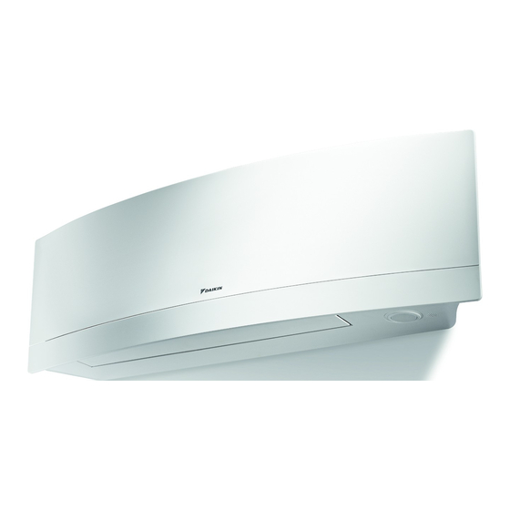
Summary of Contents for Daikin Emura FTXJ-MW
-
Page 1: Table Of Contents
Installation manual Split system air conditioners Installation manual FTXJ35MV1BW6 English Split system air conditioners FTXJ35MV1BS6... -
Page 2: Table Of Contents
▪ A subset of the latest technical data is available on the regional 9 Configuration Daikin website (publicly accessible). To set a different address............▪ The full set of latest technical data is available on the Daikin Business Portal (authentication required). 10 Commissioning 10.1 Checklist before commissioning.......... -
Page 3: About The Box
ONLY use WARNING accessories, optional equipment and spare parts made or ▪ All wiring MUST be performed by an authorised approved by Daikin. electrician and MUST comply with the applicable legislation. ▪ Make electrical connections to the fixed wiring. -
Page 4: About The Unit
▪ the mounting plate attached to the back of the indoor unit, INFORMATION ▪ the spare SSID sticker located on the front grille. ▪ Daikin Industries Czech Republic s.r.o. declares that the radio equipment type inside of this unit is in compliance with Directive 2014/53/EU. -
Page 5: Mounting The Indoor Unit
5 Unit installation Through-the-wall hole Ø65 mm ▪ Wall insulation. When conditions in the wall exceed 30°C and a Drain hose position relative humidity of 80%, or when fresh air is inducted into the Position for the tape measure at symbol " " wall, then additional insulation is required (minimum 10 ... -
Page 6: Connecting The Drain Piping
5 Unit installation 5.3.2 To connect the piping on left side, left- back, or left-bottom INFORMATION The factory default is right-side piping. For left-side piping, remove the piping from the right side and install it on the left side. 1 Remove the insulation fixing screw on the right side and remove the drain hose. -
Page 7: Piping Installation
6 Piping installation 6.2.1 To connect the refrigerant piping to the Piping installation indoor unit Preparing refrigerant piping WARNING: MILDLY FLAMMABLE MATERIAL The refrigerant inside this unit is mildly flammable. 6.1.1 Refrigerant piping requirements ▪ Pipe length. Keep refrigerant piping as short as possible. 1 Connect refrigerant piping to the unit using flare connections. -
Page 8: Specifications Of Standard Wiring Components
8 Finishing the indoor unit installation Specifications of standard wiring components Component Interconnection cable 4-core cable (indoor↔outdoor) 1.5 mm²~2.5 mm² and applicable for 220~240 V H05RN-F (60245 IEC 57) To connect the electrical wiring to the indoor unit Electrical work should be carried out in accordance with the installation manual and the national electrical wiring rules or code of practice. -
Page 9: To Pass The Pipes Through The Wall Hole
9 Configuration 2 Press the bottom frame of the unit with both hands to set it on the bottom hooks of the mounting plate. Make sure that the wires do NOT get squeezed anywhere. Note: Take care that the interconnection cable does NOT get caught in the indoor unit. -
Page 10: Commissioning
The fuses or locally installed protection devices are Daikin website (publicly accessible). installed according to this document, and have NOT been ▪ The full set of latest technical data is available on the Daikin bypassed. Business Portal (authentication required). The power supply voltage matches the voltage on the identification label of the unit. -
Page 11: Unified Wiring Diagram Legend
12 Technical data 12.1.1 Unified wiring diagram legend Symbol Meaning Stepper motor For applied parts and numbering, refer to the wiring diagram on the Compressor motor unit. Part numbering is by Arabic numbers in ascending order for each part and is represented in the overview below by "*" in the part Fan motor code. - Page 12 DAIKIN ISITMA VE SOĞUTMA SİSTEMLERİ SAN.TİC. A.Ş. Head Office: Gülsuyu Mahallesi, Fevzi Çakmak Caddesi, Burçak Sokak No:20 34848 Maltepe - İstanbul / TÜRKİYE Factory: Kargalıhanbaba OSB Mahallesi, Organize Sanayi 1 Sokak No:28 54300 Hendek - Sakarya / TÜRKİYE 3P482320-15Z 2021.10...


