Table of Contents
Advertisement
Advertisement
Table of Contents

Related Manuals for HP ProCurve 1400-24G


Summary of Contents for HP ProCurve 1400-24G
- Page 1 ProCurve Switch 1400-24G www.procurve.com Installation and Getting Started Guide...
- Page 3 ProCurve Switch 1400-24G Installation and Getting Started Guide...
- Page 4 The only warranties for HP products and services are set forth in the express warranty statements accompanying such products and services. Nothing herein should be construed as constituting an additional warranty. HP shall not be liable for technical or editorial errors or omissions contained herein.
-
Page 5: Table Of Contents
Testing the Switch by Resetting It ....... . . 3-3... - Page 6 Connectors ..........A-2 Safety .
-
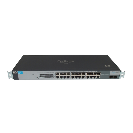
Page 7: Switch Overview
ProCurve mini-GBIC for fiber-optic connections. By default, the RJ-45 connectors are enabled. This switch is designed to be used primarily as a high-density wiring closet or desktop switch. With this switch you can directly connect computers, printers, and servers to provide dedicated bandwidth to those devices, and you can build a switched network infrastructure by connecting the switch to hubs, other switches, or routers. -
Page 8: Leds
Switch Overview Switch Hardware Features LEDs The front panel of the switch provides status LEDs for system monitoring. The following table details the functions of the various indicators. System LED State Meaning Power The switch is receiving power. (green) The switch is NOT receiving power. -
Page 9: Switch Features
10/100 Mbps switch or hub is connected to the port, it configures the port as MDI; if the switch detects that a 10/100 Mbps end-node device is connected to the port, it configures the port as MDI-X. -
Page 11: Installing The Switch
Installing the Switch The ProCurve Switch 1400-24G device is easy to install. It comes with an accessory kit that includes the brackets for mounting the switch in a standard 19-inch telco rack, in an equipment cabinet, and with rubber feet that can be attached so the switch can be securely located on a horizontal surface. -
Page 12: Installation Procedure
Mount the switch Connect power to the switch Connect the network cables Installation Precautions Follow these precautions when installing the switch. ■ The rack or cabinet should be adequately secured to prevent it W A R N I N G from becoming unstable and/or falling over. -
Page 13: Prepare The Installation Site
If your installation requires a different power cord than the one supplied ■ with the switch, be sure to use a power cord displaying the mark of the safety agency that defines the regulations for power cords in your country. The mark is your assurance that the power cord can be used safely with the switch. -
Page 14: Verify The Switch Passes Self Test
At least 7.6 cm (3 inches) of space for the twisted-pair and fiber-optic cabling. At least 3.8 cm (1 1/2 inches) of space for the power cord and switch cooling. At least 7.6 cm (3 inches) for cooling, except if the switch is installed in an open EIA/TIA rack. - Page 15 The Speed LED remains on indicating the default LED mode. • • The port LEDs on the front of the switch go into their normal opera- tional mode: – If the ports are connected to active network devices, the Link LEDs stay on and the Mode LEDs behave according to the mode selected.
-
Page 16: Mount The Switch
Rack or Cabinet Mounting The switch is designed to be mounted in any EIA-standard 19-inch telco rack or communication equipment cabinet. Note that the mounting brackets have multiple mounting holes and can be rotated allowing for a wide variety of mounting options. - Page 17 The mounting brackets have multiple mounting holes and can be rotated allowing for a wide variety of mounting options. These include mounting the switch so its front face is flush with the face of the rack, or mounting it in a more balanced position as shown in the illustration.
- Page 18 Installing the Switch Installation Procedure Place the switch in the rack and lower it so the notches in the bottom of the bracket slide onto the screws, then tighten these screws. Lower switch with mounting brackets onto the partially installed screw Install the other number 12-24 screw into the upper hole in each bracket.
- Page 19 Wall Mounting You can mount the switch on a wall with either the front or rear panel facing W A R N I N G For safe operation, please read the “Installation Precautions” on page 2-2 It is recommended the switch be mounted with the ports facing up or downward.
-
Page 20: Connect The Switch To A Power Source
Horizontal Surface Mounting Place the switch on a table or other horizontal surface. The switch comes with rubber feet in the accessory kit that can be used to help keep the switch from sliding on the surface. Attach the rubber feet to the four corners on the bottom of the switch within the embossed angled lines. -
Page 21: Installing Or Removing Mini-Gbics
Installing the mini-GBICs: Remove the protective plastic cover and retain it for later use. Hold the mini- GBIC by its sides and gently insert it into either of the slots on the switch until the mini-GBIC clicks into place. W A R N I N G The ProCurve mini-GBICs are Class 1 and 1M laser devices. - Page 22 (you can see it move outward slightly), and then pull it from the slot. To remove the mini-GBICs that have the wire bail, lower the bail until it is approximately horizontal, and then using the bail, pull the mini-GBIC from the slot.
-
Page 23: Troubleshooting
Troubleshooting This section describes how to troubleshoot the switch. This chapter describes the following: basic troubleshooting tips ■ ■ diagnosing with the LEDs testing the switch by resetting It ■ ■ ProCurve Networking Customer Support Services Basic Troubleshooting Tips Common problems and their solutions are listed in the following table. -
Page 24: Diagnosing With The Leds
Diagnostic Tips: Problem ➊ The switch is not 1. Verify the power cord is plugged into an active power source and to the switch. Make plugged into an sure these connections are snug. active AC power 2. Try power cycling the switch by unplugging and plugging the power cord back in. -
Page 25: Testing The Switch By Resetting It
Testing the Switch by Resetting It If you believe the switch is not operating correctly, you can reset the switch to test its circuitry and operating code. To reset a switch: ■ Unplug and plug in the power cord (power cycling) Power cycling the switch cause the switch to perform its power-on self test, which almost always will resolve any temporary operational problems. -
Page 27: A Switch Specifications
Switch Specifications Physical Width: Depth: Height: Weight: Electrical The switch automatically adjusts to any voltage between 100-127 volts, 200-240 volts and either 50 or 60 Hz. AC voltage: Maximum current: Frequency range: Environmental Temperature: Relative humidity: (non-condensing) Maximum altitude: 44.2 cm (17.4 in) 17.4 cm (6.9 in) -
Page 28: Connectors
Switch Specifications Connectors ■ The 10/100/1000 Mbps RJ-45 twisted-pair ports are compatible with the following standards: • IEEE 802.3ab 1000Base-T • IEEE 802.3u 100Base-TX • IEEE 802.3 10Base-T ■ The 1000 Mbps LC fiber-optic ports on the Gigabit-SX and Gigabit-LX mini- GBIC transceivers are compatible with the IEEE 802.3z Gigabit-SX and... -
Page 29: B Safety And Emc Regulatory Statements
These products do not have a power switch; they are powered on when the power cord is plugged in. Documentation reference symbol. If the product is marked with this symbol, refer to the product documentation to get more information about the product. - Page 30 Safety and EMC Regulatory Statements Safety Information Informations concernant la sécurité WARNING CAUTION Cet appareil est un produit de classe I et possède une borne de mise à la terre. La source d'alimentation principale doit être munie d'une prise de terre de sécurité installée aux bornes du câblage d'entrée, sur le cordon d'alimentation ou le cordon de raccordement fourni avec le produit.
-
Page 31: Hinweise Zur Sicherheit
Hinweise zur Sicherheit Symbol für Dokumentationsverweis. Wenn das Produkt mit diesem Symbol markiert ist, schlagen Sie bitte in der Produktdokumentation nach, um mehr Informationen über das Produkt zu erhalten. WARNING Eine WARNING in der Dokumentation symbolisiert eine Gefahr, die Verletzungen oder sogar Todesfälle verursachen kann. CAUTION CAUTION in der Dokumentation symbolisiert eine Gefahr, die dis Gerät beschädigen kann. -
Page 32: Considerazioni Sulla Sicurezza
Safety and EMC Regulatory Statements Safety Information Considerazioni sulla sicurezza WARNING CAUTION Questo prodotto è omologato nella classe di sicurezza I ed ha un terminale protettivo di collegamento a terra. Dev'essere installato un collegamento a terra di sicurezza, non interrompibile che vada dalla fonte d'alimentazione principale ai terminali d'entrata, al cavo d'alimentazione oppure al set cavo d'alimentazione fornito con il prodotto. -
Page 33: Consideraciones Sobre Seguridad
Consideraciones sobre seguridad Símbolo de referencia a la documentación. Si el producto va marcado con este símbolo, consultar la documentación del producto a fin de obtener mayor información sobre el producto. WARNING Una WARNING en la documentación señala un riesgo que podría resultar en lesiones o la muerte. -
Page 34: Safety Information
Safety and EMC Regulatory Statements Safety Information Safety Information (Japan) - Page 35 Safety and EMC Regulatory Statements Safety Information Safety Information (China)
-
Page 36: Emc Regulatory Statements
Safety and EMC Regulatory Statements EMC Regulatory Statements EMC Regulatory Statements U.S.A. FCC Class A This equipment has been tested and found to comply with the limits for a Class A digital device, pursuant to part 15 of the FCC Rules. These limits are designed to provide reasonable protection against harmful interference when the equipment is operated in a commercial environment. - Page 37 Safety and EMC Regulatory Statements EMC Regulatory Statements Japan VCCI Class A...
- Page 38 Safety and EMC Regulatory Statements EMC Regulatory Statements Korea Taiwan B-10...
-
Page 39: European Community
8000 Foothills Blvd Roseville, CA 95747-5502 U.S.A. declares that the product: Product Name: ProCurve Switch 1800-24G, 1400-24G, and 1700-24 Model Number: J9028A, J9078A, and J9080A Accessories: J4858B, J4859B, and J4860B Regulatory Model Number: RSVLC-0510 conforms to the following Product Specifications:... -
Page 41: C Recycle Statements
Recycle Statements Waste Electrical and Electronic Equipment (WEEE) Statements Disposal of Waste Equipment by Users in Private Household in the European Union This symbol on the product or on its packaging indicates that this product must not be disposed of with your other household waste. - Page 42 Recycle Statements Waste Electrical and Electronic Equipment (WEEE) Statements Laitteiden hävittäminen kotitalouksissa Euroopan unionin alueella Jos tuotteessa tai sen pakkauksessa on tämä merkki, tuotetta ei saa hävittää kotitalousjätteiden mukana. Tällöin hävitettävä laite on toimitettava sähkölaitteiden ja elektronisten laitteiden kierrätyspisteeseen. Hävitettävien laitteiden erillinen käsittely ja kierrätys auttavat säästämään luonnonvaroja ja varmistamaan, että...
- Page 43 Smaltimento delle apparecchiature da parte di privati nel territorio dell'Unione Europea Questo simbolo presente sul prodotto o sulla sua confezione indica che il prodotto non può essere smaltito insieme ai rifiuti domestici. È responsabilità dell'utente smaltire le apparecchiature consegnan- dole presso un punto di raccolta designato al riciclo e allo smaltimento di apparecchiature elettriche ed elettroniche.
- Page 44 Para obter mais informações sobre locais que reciclam esse tipo de material, entre em contato com o escritório da HP em sua cidade, com o serviço de coleta de lixo ou com a loja em que o produto foi adquirido.
- Page 45 … 2-6, 2-9 cables connecting cables to switch ports … 2-10–2-11 infrastructure requirements … 2-3 cabling infrastructure … 2-3 connecting the switch to a power source … 2-10 connector specifications … A-2 description LEDs … 1-2 switch … 1-1 electrical specifications, switch …...
- Page 46 … 2-2 preparing the installation site … 2-3 rack mounting precautions … 2-2 mounting the switch in … 2-6, 2-9 recycle statements … C-1 regulatory statements … B-8 safety and regulatory statements … B-1 safety specifications … A-2 self test LED behavior during …...
- Page 48 Technical information in this document is subject to change without notice. © Copyright 2007 Hewlett-Packard Development Company, L.P. Reproduction, adaptation, or translation without prior written permission is prohibited except as allowed under the copyright laws. Printed in China February 2007 Manual Part Number 5991-6219 *5991-6219*...