Mitsubishi Electric UL7400U Manual
Hide thumbs
Also See for UL7400U:
- User manual (68 pages) ,
- Manual (14 pages) ,
- Reference manual (2 pages)

Related Manuals for Mitsubishi Electric UL7400U


Summary of Contents for Mitsubishi Electric UL7400U
- Page 1 LCD PROJECTOR MODEL UL7400U User Manual UL7400 This User Manual is important to you. Please read it before using your projector.
- Page 2 CAUTION RISK OF ELECTRIC SHOCK DO NOT OPEN CAUTION : TO REDUCE THE RISK OF ELECTRIC SHOCK, DO NOT REMOVE COVER (OR BACK) NO USER-SERVICEABLE PARTS INSIDE REFER SERVICING TO QUALIFIED SERVICE PERSONNEL. The lightning flash with arrowhead symbol within an equilateral triangle is intended to alert the user to the presence of uninsulated “dangerous voltage”...
-
Page 3: Table Of Contents
Contents Important safeguards ........................4 Preparing your projector ........................6 Using the remote control ........................9 Setting up your projector .........................11 Viewing computer images .......................18 Viewing video images ........................25 Menu operation ..........................30 Adjusting projected images ......................39 Initial network settings ........................44 Advanced features ..........................48 Replacing the lamp .........................53 Maintenance ............................55 Roll-up filter .............................56... -
Page 4: Important Safeguards
Important safeguards Please read all these instructions regarding your 10. Power sources projector and retain them for future reference. Follow This projector should be operated only from the all warnings and instructions marked on the projector. type of power source indicated on the marking label. - Page 5 Important safeguards (continued) WARNING: Do not use the projector with condensation on it. It can lead to breakdown or other failure. Unplug immediately if there is something Place of installation wrong with your projector. For safety’s sake, refrain from setting the projector at any Do not operate if smoke, strange noise or odor comes out place subjected to high temperature and high humidity.
-
Page 6: Preparing Your Projector
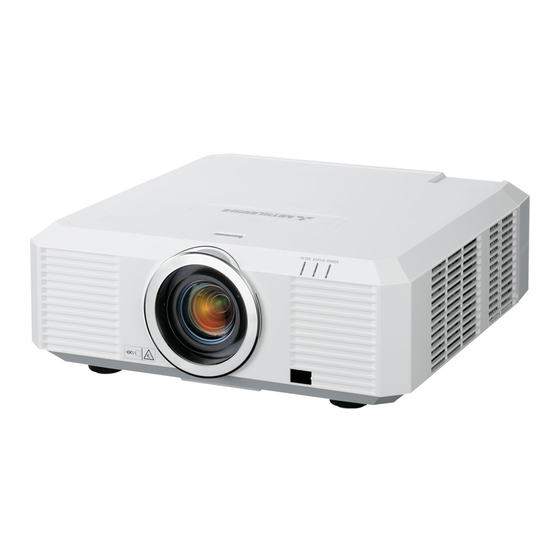
Preparing your projector Checking accessories The following accessories are provided with this projector. Check to be sure that all of the accessories are packed in the package. Cables Power supply part Mini D-SUB D-SUB 15-pin 9-pin Mini D-SUB D-SUB 15-pin 9-pin RS-232C cable Computer cable... - Page 7 Preparing your projector (continued) Overview 1 Speaker 2 Lens release button 3 Indicators 4 Air inlet grille/Filter cover 5 Air inlet grille 6 Lens 7 Remote control sensor (front) 8 Remote control sensor (rear) 9 Control area 10 Terminal panel 11 Air outlet grille 12 Air inlet grille Caution:...
- Page 8 Preparing your projector (continued) Indicators Bottom side 1 Lock bar (SECURITY ANCHOR) • Attach a chain, etc. to this lock bar to anchor the projector. 2 Adjustment feet 1 FILTER indicator 2 STATUS indicator 3 POWER indicator Remote control 1 Indicator 2 POWER button (ON/STANDBY) The status is changed between ON and STANDBY. 3 COMPUTER 1, 2 buttons 4 MENU button 5 BLANK button...
-
Page 9: Using The Remote Control
Using the remote control Operational range of the remote control Front of projector Rear of projector About 30° About 30° About 30° About 30° Operate the remote control within a distance of 30 m (98.4 feet) from the projector, pointing the light beam at the remote control photo-sensor (front or rear) of the projector. - Page 10 Using the remote control (continued) Setting the ID number of the remote “COMPLETE” is displayed under the CONTROLLER ID number you entered. control • The ID setting dialog box automatically You can control multiple projectors collectively or disappears after it is displayed for about 5 individually using one remote control by setting the ID seconds.
-
Page 11: Setting Up Your Projector
Setting up your projector Before setting up Before setting up the projector, check the operating environment. If the environmental requirements are not satisfied, the projector may break down or fail. Setup environment The allowable operating temperature varies depending on the HIGH ALTITUDE MODE setting. For use in the STANDARD mode, the allowable operating temperature is +41°F (+5°C) to +104°F (+40°C). - Page 12 Setting up your projector (continued) Setup adjustment • When the ENTER button is pressed while the LENS SHIFT menu is displayed, the shift mode can be switched between FAST and STEP. When FAST How to turn on the projector is selected, the lens shifts in a large amount with When you have to turn on the projector for setup the , , ...
- Page 13 Setting up your projector (continued) Setting HIGH ALTITUDE MODE Correcting skewed or distorted • Set HIGH ALTITUDE MODE in the FEATURE menu image according to the altitude at which you use the For the best projection, project images on a flat screen projector. The default setting is STANDARD. installed at 90 degrees to the floor.
- Page 14 Setting up your projector (continued) Adjustment using the KEYSTONE mode: effect, the resolution decreases. In addition, stripes may appear or straight lines may bend in images When the screen and the projector are not placed with complicated patterns. They are not due to perpendicularly to each other, projected images product malfunctions.
- Page 15 Setting up your projector (continued) LOWER RIGHT, LOWER LEFT, UPPER RIGHT, or ARC menu UPPER LEFT menu You can correct the arc vertically or horizontally You can adjust the horizontal or vertical position of the focusing on the screen center. selected corner.
- Page 16 Setting up your projector (continued) Important: • When the horizontal arc adjustment is positive (+) (or the ARC is adjusted in the direction) • When the CURVED-mode adjustment takes effect, the resolution decreases. In addition, stripes may appear or straight lines may bend in images with complicated patterns. They are not due to product malfunctions.
- Page 17 Setting up your projector (continued) Front projection, ceiling mounting Rear projection For ceiling mounting, you need the ceiling mount Ask a specialist for installation. For details, consult kit designed for this projector. Ask a specialist for your dealer. installation. For details, consult your dealer. • The warranty on this projector does not cover any damage caused by use of any non-recommended ceiling mount kit or installation of the ceiling mount...
-
Page 18: Viewing Computer Images
Viewing computer images A. Connecting the projector to a computer Preparation: • Make sure that the power of the projector and that of the computer are turned off. • When connecting the projector to a desktop computer, disconnect the computer cable that is connected to the monitor. Computer For analog connection: (For using the COMPUTER/COMPONENT/VIDEO IN 1 terminal.) COMPUTER/ 1. Connect one end of the supplied computer cable to the COMPONENT/ COMPUTER/COMPONENT/VIDEO IN 1 terminal of the VIDEO IN 1 projector. - Page 19 Viewing computer images (continued) For monitor connection: Monitor 1. Connect the computer cable from the monitor to the MONITOR OUT terminal of the projector. • Only when STANDBY MODE is set to STANDARD, video signal is output from the MONITOR OUT terminal during power standby. MONITOR OUT Computer cable For audio output connection: 1.
- Page 20 Viewing computer images (continued) Caution: • Plug in the power cord firmly. When unplugging, hold and pull the power plug, not the power cord. • Do not plug in or out the power cord with your hand wet. It may cause electric shock. • Do not turn on the power before attaching the lens. The cabinet may be exposed to the light from the lamp directly and heated to a high temperature, resulting in deformation.
- Page 21 Viewing computer images (continued) D. Projecting images Preparation: • Remove the lens cap. POWER button POWER button (ON/STANDBY) (ON/STANDBY) COMPUTER 1, 2 buttons , , , buttons DVI-D(HDCP) POWER indicator button STATUS indicator ENTER button COMPUTER/DVI-D button , , , buttons ENTER button LENS SHIFT button ZOOM/FOCUS button...
- Page 22 Viewing computer images (continued) 9. Press the ZOOM/FOCUS button to display the ZOOM/FOCUS menu. 10. Adjust with the or button to get an approximate size. • When the ENTER button is pressed while the ZOOM/FOCUS menu is displayed, the adjustment mode is switched between FAST and STEP. When FAST is selected, the speed of zoom controlled by the or button becomes fast, and it becomes slow when STEP is selected.
- Page 23 Viewing computer images (continued) Blanking the screen temporarily (BLANK) The video and audio signals are temporarily muted when the BLANK button is pressed. You will hear an operating sound inside the projector. To cancel muting, press the BLANK button again. • You can alter the splash screen optionally. See page 33.
- Page 24 Viewing computer images (continued) Setting the aspect ratio You can change the aspect ratio of the input video signal (or the ratio of width to height of the image). Change the setting according to the type of the screen to be used or your preference. How to change the settings: With the remote control: 1.
-
Page 25: Viewing Video Images
Viewing video images A. Connecting the projector to video equipment Preparation: • Make sure that the power of the projector and that of the video equipment are turned off. Connecting to a video player, etc. 1. Connect one end of a commercially available BNC cable to Video player, or the like BNC cable (option) the VIDEO IN terminal of the projector. - Page 26 Viewing video images (continued) Projector + DVD player or HDTV decoder Some DVD players have an output connector for 3-line fitting (Y, C ). When connecting such DVD player with this projector, use the COMPUTER/COMPONENT/VIDEO IN 2 terminals. BNC cable (option) COMPUTER/COMPONENT/ VIDEO IN 2 BNC-RCA connector (option)
- Page 27 Viewing video images (continued) Connection (for video equipment having a DVI-D terminal) DVI cable (option) COMPUTER/COMPONENT/ VIDEO DVI-D IN (HDCP) To DVI-D terminal AUDIO DVI-D Audio cable (option) To audio output Equipment having a terminals DVI-D terminal • For connection to the DVI-D terminal, use a commercially available DVI cable. • Use AUDIO DVI-D terminal for audio input. • Some cables may not be connected correctly depending on the size and shape of their connectors.
- Page 28 Viewing video images (continued) D. Projecting images Preparation: • Remove the lens cap. POWER button POWER button (ON/STANDBY) (ON/STANDBY) HDMI button COMPUTER 1, 2 buttons VIDEO button , , , buttons S-VIDEO button DVI-D(HDCP) button POWER indicator STATUS indicator COMPUTER/DVI-D button ENTER button VIDEO/HDMI button , , , ...
- Page 29 Viewing video images (continued) 11. Press the LENS SHIFT button. The LENS SHIFT menu appears at the center of the screen. 12. Press the or button to adjust the vertical position and or button to adjust the horizontal position of the displayed image.
-
Page 30: Menu Operation
Menu operation You can make various settings using the displayed menus. Following 6 menus are displayed. IMAGE menu (page 32) INSTALLATION menu (page 33) FEATURE menu (page 34) opt. opt. opt. INSTALLATION IMAGE FEATURE COLOR ENHANCER AUTO LAMP MODE STANDARD ASPECT NORMAL SUPER RESOLUTION... - Page 31 Menu operation (continued) How to set the menus 1. Press the MENU button. • The menu selection bar is displayed. Selectable menus are displayed by icons. (The menu icon being selected is displayed on a blue background.) opt. IMAGE The name of the menu being selected is displayed.
- Page 32 Menu operation (continued) IMAGE menu opt. opt. IMAGE IMAGE ADVANCED MENU COLOR ENHANCER AUTO SUPER RESOLUTION AUTO IRIS CONTRAST NOISE REDUCTION BRIGHTNESS INPUT LEVEL COMPUTER CLOSED CAPTION COLOR TEMP. STANDARD COLOR TINT SHARPNESS ADVANCED MENU ENTER ITEM SETTING FUNCTION COLOR ENHANCER AUTO Select to optimize the settings automatically depending on the input signal.
- Page 33 Menu operation (continued) INSTALLATION menu opt. opt. INSTALLATION INSTALLATION LENS LOCK LAMP MODE STANDARD STANDBY MODE ZOOM/FOCUS LOCK AUTO POWER ON LENS SHIFT LOCK LENS SHIFT RESET AUTO POWER OFF 5min IMAGE CAPTURE SETUP SPLASH SCREEN BACK COLOR BLUE IMAGE REVERSE LENS LOCK ENTER DVI LONG CABLE...
- Page 34 Menu operation (continued) FEATURE menu opt. opt. FEATURE FEATURE ADVANCED MENU ASPECT NORMAL AUTO SCREEN 16:10 VIDEO SIGNAL SETUP PROJECTOR ID AUTO SCART INPUT PASSWORD FUNCTION DISPLAY INPUT LAMP WARNING STANDARD MENU POSITION HIDE OSD CINEMA MODE AUTO FILTER MENU ENTER LANGUAGE English...