Table of Contents
Advertisement
Quick Links
www.ti.com
User's Guide
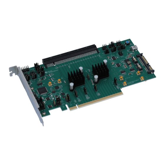
DS160PT801X16EVM Riser Card Evaluation Module
The DS160PT801X16EVM is a 16-lane PCIe riser card board intended to be used for evaluation of the
Texas Instruments DS160PT801 PCIe Gen4 retimer. The EVM uses the 1x16 Card Electromechanical (CEM)
connector to enable quick system testing in a standard x16 socket and a standard PCIe endpoint. The evaluation
board may be used with the SigCon Architect software program to provide register control and status information
from the DS160PT801 devices. Contact a local Texas Instruments representative to obtain the SigCon Architect.
1.1 Retimer Pin Controls..........................................................................................................................................................
Interface....................................................................................................................................................4
1.3 PCIe PRSNT# Signal Control and Configuration...............................................................................................................
2 EVM Power..............................................................................................................................................................................
2.1 EVM Current Sensing........................................................................................................................................................
3 SigCon Architect GUI.............................................................................................................................................................
Installation.........................................................................................................................................................9
3.2 Configuration Page..........................................................................................................................................................
Page................................................................................................................................................................11
3.4 EEPROM Page................................................................................................................................................................
3.5 Control Panel...................................................................................................................................................................
SNLU254A - NOVEMBER 2020 - REVISED JULY 2022
Submit Document Feedback
ABSTRACT
Figure 1-1. DS160PT801 EVM
Table of Contents
Information........................................................................................................................3
Configuration..............................................................................................................5
Copyright © 2022 Texas Instruments Incorporated
DS160PT801X16EVM Riser Card Evaluation Module
Table of Contents
3
5
7
8
9
10
12
13
1
Advertisement
Table of Contents

Related Manuals for Texas Instruments DS160PT801X16EVM


Summary of Contents for Texas Instruments DS160PT801X16EVM
-
Page 1: Table Of Contents
DS160PT801X16EVM Riser Card Evaluation Module ABSTRACT The DS160PT801X16EVM is a 16-lane PCIe riser card board intended to be used for evaluation of the Texas Instruments DS160PT801 PCIe Gen4 retimer. The EVM uses the 1x16 Card Electromechanical (CEM) connector to enable quick system testing in a standard x16 socket and a standard PCIe endpoint. The evaluation board may be used with the SigCon Architect software program to provide register control and status information from the DS160PT801 devices. - Page 2 6 Hardware BOM..................................7 Revision History................................... List of Figures Figure 1-1. DS160PT801 EVM..............................Figure 1-1. DS160PT801X16EVM EEPROM Control and Connection..................Figure 1-2. DS160PT801X16EVM SMBus Interface Connections....................Figure 1-3. DS160PT801X16EVM PCIe PRSNT# Controls......................Figure 1-4. Common Clock Topology Example........................... Figure 1-5. Independent Clock Topology Example........................
-
Page 3: Evm Control And Configuration Information
EVM. 1.1 Retimer Pin Controls The DS160PT801X16EVM is pre-configured on power-up to use the retimer configuration stored in the onboard EEPROM. These settings may be adjusted by using the pin controls through the onboard headers and jumpers. -
Page 4: Usb-To-Smbus Interface
1.2 USB-to-SMBus Interface The DS160PT801X16EVM uses an onboard MSP430 microcontroller to create USB-to-SMBus interface. The USB-to-SMBus interface is intended to be used with Texas Instruments software like SigCon Architect to communicate to the DS160PT801 retimers. When using the default jumper configuration listed in... -
Page 5: Pcie Prsnt# Signal Control And Configuration
EVM Control and Configuration Information Figure 1-2. DS160PT801X16EVM SMBus Interface Connections To access the DS160PT801 devices through this interface, power must be applied through the SATA or Gold Finger connectors. 1.3 PCIe PRSNT# Signal Control and Configuration The riser card allows users to alter the hot-plug presence detect signal (PRSNT#) returned to the PCIe host sytem. -
Page 6: Figure 1-4. Common Clock Topology Example
Net: REFCLKP/N_EP DNI: R1, R2 Straddle connector CDCE6214 SMPs 25 MHz XTAL Figure 1-5. Independent Clock Topology Example DS160PT801X16EVM Riser Card Evaluation Module SNLU254A – NOVEMBER 2020 – REVISED JULY 2022 Submit Document Feedback Copyright © 2022 Texas Instruments Incorporated... -
Page 7: Evm Power
SATA PWR Connector +5.0V TPS73533 MSP430: 3.3V Net: tx_VBUS Net: tx_3P3V_MSP USB Connector Figure 2-2. DS160PT801X16EVM Power Network SNLU254A – NOVEMBER 2020 – REVISED JULY 2022 DS160PT801X16EVM Riser Card Evaluation Module Submit Document Feedback Copyright © 2022 Texas Instruments Incorporated... -
Page 8: Evm Current Sensing
The voltages measured at this connector can be used to calculate the efficiency of the voltage regulator and the current delivered to each DS160PT801 device. Figure 2-3. DS160PT801X16EVM Current Sense Measurement Locations Equation 1... -
Page 9: Sigcon Architect Gui
SigCon Architect GUI 3 SigCon Architect GUI The SigCon Architect GUI is designed to be used in conjunction with the DS160PT801X16EVM. By communicating to the two onboard retimers through the included USB cable, the status of the retimers and PCIe link can be assessed using a graphical interface. -
Page 10: Configuration Page
GUI without an active retimer connection. This may be used to create EEPROM images, view the register map, or evaluate other portions of the DS160PT801 GUI. DS160PT801X16EVM Riser Card Evaluation Module SNLU254A – NOVEMBER 2020 – REVISED JULY 2022 Submit Document Feedback Copyright ©... -
Page 11: Low-Level Page
Save Config Button saves a file that stores the current values for all SBMus registers. This file can later be loaded using the Load Config button. SNLU254A – NOVEMBER 2020 – REVISED JULY 2022 DS160PT801X16EVM Riser Card Evaluation Module Submit Document Feedback Copyright © 2022 Texas Instruments Incorporated... -
Page 12: Eeprom Page
Mask Select Dropdown, combined with the Device Select dropdown, modifies the SMBus addresses that are effected by the currently displayed configuration set. The DS160PT801 EEPROM Programming Guide is available upon request. DS160PT801X16EVM Riser Card Evaluation Module SNLU254A – NOVEMBER 2020 – REVISED JULY 2022 Submit Document Feedback... -
Page 13: Control Panel
Channel Select Dropdown selects the active channel being configured. It is enabled in the High-Level page when modifying the Rx/Tx EQ settings, the Diagnostic page, and Eye Monitor pages. SNLU254A – NOVEMBER 2020 – REVISED JULY 2022 DS160PT801X16EVM Riser Card Evaluation Module Submit Document Feedback Copyright © 2022 Texas Instruments Incorporated... -
Page 14: High-Level Page
Refresh From Device Button refreshes data in the GUI by downloading the current SMBus configuration of the retimer. 3.6 High-Level Page Figure 3-5. High-Level Page Screenshot DS160PT801X16EVM Riser Card Evaluation Module SNLU254A – NOVEMBER 2020 – REVISED JULY 2022 Submit Document Feedback Copyright © 2022 Texas Instruments Incorporated... -
Page 15: Figure 3-6. High-Level Page - Device Status Screenshot
Edit Field Visibility Button allows a user to show or hide different columns within the channel status table. SNLU254A – NOVEMBER 2020 – REVISED JULY 2022 DS160PT801X16EVM Riser Card Evaluation Module Submit Document Feedback Copyright © 2022 Texas Instruments Incorporated... -
Page 16: Figure 3-7. High Level Page - Device Status (Active Link)
Edit Field Visibility Button allows a user to show or hide different columns within the channel status table. Figure 3-8. High-Level – Rx EQ/DFE Page DS160PT801X16EVM Riser Card Evaluation Module SNLU254A – NOVEMBER 2020 – REVISED JULY 2022 Submit Document Feedback... -
Page 17: Figure 3-9. High-Level Page Tx Fir
Post Cursor Tap Field sets the post cursor value for the Tx FIR. • Co efficient abs Sum Field displays the absolute value of the Pre, Post, and Main cursor. SNLU254A – NOVEMBER 2020 – REVISED JULY 2022 DS160PT801X16EVM Riser Card Evaluation Module Submit Document Feedback Copyright © 2022 Texas Instruments Incorporated... -
Page 18: Diagnostic Page
Error Count Graph displays the amount of errors accumulated by the PRBS checker over time. • Clear Checker Button clears the error count graph. DS160PT801X16EVM Riser Card Evaluation Module SNLU254A – NOVEMBER 2020 – REVISED JULY 2022 Submit Document Feedback... -
Page 19: Eye Monitor Page
Export Density exports the results of an eye diagram including error density information. • Clear Plots clears the Raw Data, Error Hit Count, and Contour data graphs. SNLU254A – NOVEMBER 2020 – REVISED JULY 2022 DS160PT801X16EVM Riser Card Evaluation Module Submit Document Feedback Copyright © 2022 Texas Instruments Incorporated... -
Page 20: Pcb Material Information
PCIe clock traces are 100-Ω target 4.2 DS160PT801 PCB Stackup Figure 4-1 illustrates the DS160PT801X16EVM PCB stackup. Figure 4-1. DS160PT801X16EVM PCB Stackup 4.3 DS160PT801 PCB Power Distribution The riser card power distribution network was designed for observation and performance. Four power layers were dedicated to retimer supply voltages. -
Page 21: Figure 4-2. Layer 3 High-Speed Analog Analog Power Rails
U2 retimer. This helps to compensate for any losses on the PCB between the regulator and the device load. SNLU254A – NOVEMBER 2020 – REVISED JULY 2022 DS160PT801X16EVM Riser Card Evaluation Module Submit Document Feedback Copyright © 2022 Texas Instruments Incorporated... -
Page 22: Ds160Pt801 Local Decoupling
Top and Bottom layer capacitors to optimize the overall frequency response of the decoupling solution. Figure 4-5. Decoupling Solution Frequency Response DS160PT801X16EVM Riser Card Evaluation Module SNLU254A – NOVEMBER 2020 – REVISED JULY 2022 Submit Document Feedback... -
Page 23: Figure 4-6. Pcb Top Layer
Figure 4-6. PCB Top Layer SNLU254A – NOVEMBER 2020 – REVISED JULY 2022 DS160PT801X16EVM Riser Card Evaluation Module Submit Document Feedback Copyright © 2022 Texas Instruments Incorporated... -
Page 24: Ds160Pt801X16Evm Schematic
Re v ECN # Approve d Da te Approve d by Note s Figure 5-1. Schematic – Cover Sheet DS160PT801X16EVM Riser Card Evaluation Module SNLU254A – NOVEMBER 2020 – REVISED JULY 2022 Submit Document Feedback Copyright © 2022 Texas Instruments Incorporated... -
Page 25: Figure 5-2. Schematic - High Speed
0.22uF 0.22uF 0.22uF 0.22uF 0.22uF 0.22uF 0.22uF 0.22uF 0.22uF 0.22uF C277 PRSNT2_16 Figure 5-2. Schematic – High Speed SNLU254A – NOVEMBER 2020 – REVISED JULY 2022 DS160PT801X16EVM Riser Card Evaluation Module Submit Document Feedback Copyright © 2022 Texas Instruments Incorporated... -
Page 26: Figure 5-3. Schematic - Control
SMBus Address: 1010 0 P1 P0 x RCLK_N LOC_SCL Serial Number: 1011 000 1 V3P3_F V3P3_F Figure 5-3. Schematic – Control DS160PT801X16EVM Riser Card Evaluation Module SNLU254A – NOVEMBER 2020 – REVISED JULY 2022 Submit Document Feedback Copyright © 2022 Texas Instruments Incorporated... -
Page 27: Figure 5-4. Schematic - Supply Voltage Regulators
Enabling with 3.3V supply will result in a 1.1V -> 1.8V power sequence 0.1uF INA210AIDCKR Figure 5-4. Schematic – Supply Voltage Regulators SNLU254A – NOVEMBER 2020 – REVISED JULY 2022 DS160PT801X16EVM Riser Card Evaluation Module Submit Document Feedback Copyright © 2022 Texas Instruments Incorporated... -
Page 28: Figure 5-5. Schematic - Retimer 1 Current Sense And Decoupling
10 uF cap near edge of DUT footprint. Figure 5-5. Schematic – Retimer 1 Current Sense and Decoupling DS160PT801X16EVM Riser Card Evaluation Module SNLU254A – NOVEMBER 2020 – REVISED JULY 2022 Submit Document Feedback Copyright © 2022 Texas Instruments Incorporated... -
Page 29: Figure 5-6. Schematic - Retimer 0 Current Sense And Decoupling
10 uF cap near edge of DUT footprint. Figure 5-6. Schematic – Retimer 0 Current Sense and Decoupling SNLU254A – NOVEMBER 2020 – REVISED JULY 2022 DS160PT801X16EVM Riser Card Evaluation Module Submit Document Feedback Copyright © 2022 Texas Instruments Incorporated... -
Page 30: Figure 5-7. Schematic - Pcie Gen4 Clock Generation
C_CLK_P C_CLK_P C_CLK_N C_CLK_N LMK_EP_P LMK_EP_P LMK_EP_N LMK_EP_N V1P8_CDC V1P8_CDC Figure 5-7. Schematic – PCIe Gen4 Clock Generation DS160PT801X16EVM Riser Card Evaluation Module SNLU254A – NOVEMBER 2020 – REVISED JULY 2022 Submit Document Feedback Copyright © 2022 Texas Instruments Incorporated... -
Page 31: Figure 5-8. Schematic - Pcie Gen4 Clock Buffer
R106 R108 R109 R107 49.9 49.9 49.9 49.9 49.9 LMK00334RTVR Figure 5-8. Schematic – PCIe Gen4 Clock Buffer SNLU254A – NOVEMBER 2020 – REVISED JULY 2022 DS160PT801X16EVM Riser Card Evaluation Module Submit Document Feedback Copyright © 2022 Texas Instruments Incorporated... -
Page 32: Figure 5-9. Schematic - Msp430 Microcontroller
2.2uF 60 ohm C299 C300 C301 10nF V3P3_F V3P3_F 22uF 7.5V TPS735xxDRB Figure 5-9. Schematic – MSP430 Microcontroller DS160PT801X16EVM Riser Card Evaluation Module SNLU254A – NOVEMBER 2020 – REVISED JULY 2022 Submit Document Feedback Copyright © 2022 Texas Instruments Incorporated... -
Page 33: Hardware Bom
DS160PT801X16EVM Schematic 6 Hardware BOM Table 6-1 lists the DS160PT801X16EVM BOM. Table 6-1. DS160PT801X16EVM Bill of Materials Designator Value Description Package Part Number Manufacturer C1, C2, C3, C8, C93, C181, C280, C322, C328, 10 µF CAP, CERM, 10 µF, 10 V, ± 10%, X5R, 0805... - Page 34 DS160PT801X16EVM Schematic www.ti.com Table 6-1. DS160PT801X16EVM Bill of Materials (continued) Designator Value Description Package Part Number Manufacturer C40, C73, C87, C96, C128, C161, C175, C184, 47 µF CAP, CERM, 47 µF, 6.3 V, ± 20%, X7S, 1206 1206 C3216X7S0J476M160AC C316...
- Page 35 DS160PT801X16EVM Schematic Table 6-1. DS160PT801X16EVM Bill of Materials (continued) Designator Value Description Package Part Number Manufacturer 60 Ω Ferrite Bead, 60 Ω at 100 MHz, 0.8 A, 0603 0603 BK1608HS600-T Taiyo Yuden H1, H2 MACHINE SCREW PAN PHILLIPS 4-40...
- Page 36 DS160PT801X16EVM Schematic www.ti.com Table 6-1. DS160PT801X16EVM Bill of Materials (continued) Designator Value Description Package Part Number Manufacturer 4.7k RES, 4.7 k, 5%, 0.063 W, AEC-Q200 Grade 0, 0402 CRCW04024K70JNED Vishay-Dale 0402 R16, R101, R102, R103, R104, R105, R106, 49.9 RES, 49.9, 1%, 0.063 W, 0402...
- Page 37 DS160PT801X16EVM Schematic Table 6-1. DS160PT801X16EVM Bill of Materials (continued) Designator Value Description Package Part Number Manufacturer R147 133k RES, 133 k, 1%, 0.063 W, AEC-Q200 Grade 0, 0402 CRCW0402133KFKED Vishay-Dale 0402 R148 75.0k RES, 75.0 k, 1%, 0.05 W, 0201...
- Page 38 DS160PT801X16EVM Schematic www.ti.com Table 6-1. DS160PT801X16EVM Bill of Materials (continued) Designator Value Description Package Part Number Manufacturer 4-Channel ESD Protection Array for High-Speed DRY0006A TPD4E004DRYR Texas Instruments Data Interfaces, DRY0006A (USON-6) 500 mA, Adjustable, Low Quiescent Current, DRB0008A TPS73533DRBR Texas Instruments...
-
Page 39: Revision History
Changes from Revision * (November 2020) to Revision A (July 2022) Page • First public release of user's guide ........................SNLU254A – NOVEMBER 2020 – REVISED JULY 2022 DS160PT801X16EVM Riser Card Evaluation Module Submit Document Feedback Copyright © 2022 Texas Instruments Incorporated... - Page 40 STANDARD TERMS FOR EVALUATION MODULES Delivery: TI delivers TI evaluation boards, kits, or modules, including any accompanying demonstration software, components, and/or documentation which may be provided together or separately (collectively, an “EVM” or “EVMs”) to the User (“User”) in accordance with the terms set forth herein.
- Page 41 www.ti.com Regulatory Notices: 3.1 United States 3.1.1 Notice applicable to EVMs not FCC-Approved: FCC NOTICE: This kit is designed to allow product developers to evaluate electronic components, circuitry, or software associated with the kit to determine whether to incorporate such items in a finished product and software developers to write software applications for use with the end product.
- Page 42 www.ti.com Concernant les EVMs avec antennes détachables Conformément à la réglementation d'Industrie Canada, le présent émetteur radio peut fonctionner avec une antenne d'un type et d'un gain maximal (ou inférieur) approuvé pour l'émetteur par Industrie Canada. Dans le but de réduire les risques de brouillage radioélectrique à...
- Page 43 www.ti.com EVM Use Restrictions and Warnings: 4.1 EVMS ARE NOT FOR USE IN FUNCTIONAL SAFETY AND/OR SAFETY CRITICAL EVALUATIONS, INCLUDING BUT NOT LIMITED TO EVALUATIONS OF LIFE SUPPORT APPLICATIONS. 4.2 User must read and apply the user guide and other available documentation provided by TI regarding the EVM prior to handling or using the EVM, including without limitation any warning or restriction notices.
- Page 44 Notwithstanding the foregoing, any judgment may be enforced in any United States or foreign court, and TI may seek injunctive relief in any United States or foreign court. Mailing Address: Texas Instruments, Post Office Box 655303, Dallas, Texas 75265 Copyright © 2019, Texas Instruments Incorporated...
- Page 45 TI products. TI’s provision of these resources does not expand or otherwise alter TI’s applicable warranties or warranty disclaimers for TI products. TI objects to and rejects any additional or different terms you may have proposed. IMPORTANT NOTICE Mailing Address: Texas Instruments, Post Office Box 655303, Dallas, Texas 75265 Copyright © 2022, Texas Instruments Incorporated...