Table of Contents
Advertisement
Quick Links
Advertisement
Table of Contents

Summary of Contents for Omega Engineering DPA1004
- Page 1 DPA1004 & DPA1044 Relay & I/O Expansion Modules...
- Page 2 DPA1004 & DPA1044 Expansion Modules Instruction Manual...
- Page 3 Instruction Manual WARRANTY/DISCLAIMER OMEGA ENGINEERING, INC. warrants this unit to be free of defects in materials and workmanship for a period of 13 months from date of purchase. OMEGA’s WARRANTY adds an additional one (1) month grace period to the normal one (1) year product warranty to cover handling and shipping time. This ensures that OMEGA’s customers receive maximum coverage on each product.
- Page 4 DPA1004 & DPA1044 Expansion Modules Instruction Manual CAUTION: Read complete WARNING: Risk of instructions prior to instal- electric shock or lation and operation of the personal injury. module. Expansion modules DO NOT contain internal jumpers or user settings. Hazardous voltages exist within enclosure.
-
Page 5: Table Of Contents
Accessories ------------------------------------------------------------------------ 6 SPECIFICATIONS ---------------------------------------------------------- 7 General (applicable to both models) --------------------------------------- 7 DPA1004 4-Relay Expansion Module -------------------------------------- 7 DPA1044 Digital Input & Output Expansion Module ------------------ 8 INSTALLATION ------------------------------------------------------------- 9 External Relays & Digital I/O Connections ------------------------------- 9 ... -
Page 6: Introduction
DPA1004 & DPA1044 Expansion Modules Instruction Manual INTRODUCTION These external expansion modules add functionality to any DP meter in the field. They can be added at any time and are easy-to-install. Add a 4-relay expansion module and/or up to two I/O modules. The menu items for these modules do not appear until the module is con- nected, simplifying the basic menu. -
Page 7: Specifications
DPA1004 & DPA1044 Expansion Modules Instruction Manual SPECIFICATIONS Except where noted all specifications apply to operation at +25°C. General (applicable to both models) POWER Meter M-LINK connection Standard CAT5e cable; provided with module. CABLE Note: To ensure optimum performance use only supplied cables. -
Page 8: Dpa1044 Digital Input & Output Expansion Module
DPA1004 & DPA1044 Expansion Modules Instruction Manual DPA1044 Digital Input & Output Expansion Module CHANNELS 4 digital inputs & 4 digital outputs per module Up to 2 modules for a total of 8 inputs & 8 outputs Note: The jumper located between the RJ45 connectors... -
Page 9: Installation
WARNING! External Relays & Digital I/O Connections The relay and the digital I/O expansion modules DPA1004 & DPA1044 are connected to the meter using a CAT5e cable provided with each module (see Figure 1). Figure 1: M-Link Connector Location on the Meter Do not connect any equipment other than OMEGA’s... -
Page 10: Terminal Block Connections
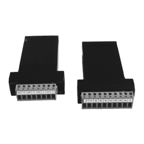
DPA1004 & DPA1044 Expansion Modules Instruction Manual Terminal Block Connections All connections are made to removable screw terminal connectors located at the front of the module. Use copper wire with 60°C or 60/75°C insulation for all line voltage connections. Observe all safety regulations. - Page 11 DPA1004 & DPA1044 Expansion Modules Instruction Manual NOTES...
- Page 12 M-5194 LIM1044OM_A 07/12...