Advertisement
Available languages
Available languages
Quick Links
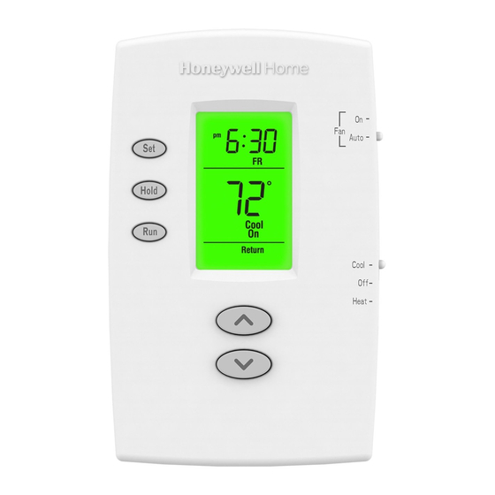
PRO TH2000DV/TH1000DV Series
Thermostats
This manual covers the following models
• TH1100DV: For Heat only systems
• TH2110DV/TH1110DV: For 1 Heat/1 Cool systems
• TH2210DV/TH1210DV: For 2 Heat/1 Cool heat pump systems only
(Pull thermostat from wallplate and turn over to find model number.)
System Types
TH2110DV/TH1110DV:
• Gas, oil, or electric heat with air
conditioning
• Warm air, hot water, high-efficiency
furnaces, 1 Heat/1 Cool heat pumps,
steam, gravity
• Heat only
• Heat only with fan
• Cool only
• 750 mV heating systems
Must be installed by a trained, experienced technician
Read these instructions carefully. Failure to follow these instructions
can damage the product or cause a hazardous condition.
For assistance with this product please visit http://customer.honeywell.com
or call Honeywell Customer Care toll-free at 1-800-468-1502
® U.S. Registered Trademark. Patents pending.
Copyright © 2013 Honeywell International Inc.
All rights reserved.
TH2210DV/TH1210DV:
• 2 Heat/1 Cool heat pumps
TH1100DV:
• Gas, oil, or electric heat
• Warm air, hot water, steam, gravity
• Heat only
• 750 mV heating systems
Need Help?
Installation
Guide
69-2800EFS-01
Advertisement

Related Manuals for Honeywell PRO TH2000DV Series


Summary of Contents for Honeywell PRO TH2000DV Series
- Page 1 • Heat only • Heat only with fan • 750 mV heating systems • Cool only • 750 mV heating systems Must be installed by a trained, experienced technician Read these instructions carefully. Failure to follow these instructions can damage the product or cause a hazardous condition. Need Help? For assistance with this product please visit http://customer.honeywell.com or call Honeywell Customer Care toll-free at 1-800-468-1502 ® U.S. Registered Trademark. Patents pending. Copyright © 2013 Honeywell International Inc. 69-2800EFS-01 All rights reserved.
- Page 2 Installation Guide Wallplate installation Remove the wallplate from the thermostat Pull at bottom to remove thermostat from wallplate. as shown at left, then follow directions below for mounting. 1. Pull wires through wire hole. 2. Position wallplate on wall, level and mark hole positions with pencil. 3. Drill holes at marked positions as shown below, then tap in supplied wall anchors. 4. Place wallplate over anchors, insert and tighten mounting screws. M34683 Drill 3/16" holes for drywall. Drill 7/32" holes for plaster. Mounting screws Wire hole USED AUX/ C IS OPTIONAL WITH BATTERIES Wall anchors M34682 CAUTION: ELECTRICAL HAZARD Can cause electrical shock or equipment damage. Disconnect power before beginning installation. MERCURY NOTICE If this product is replacing a control that contains mercury in a sealed tube, do not place the old control in the trash.
- Page 3 PRO TH2000DV/TH1000DV Series Power options INSERT BATTERIES FOR PRIMARY OR BACKUP POWER REMOVE FACTORY-INSTALLED JUMPER ONLY FOR TWO-TRANSFORMER SYSTEMS CONNECT C FOR PRIMARY AC POWER (OPTIONAL IF BATTERIES ARE INSTALLED) TERMINAL BLOCK SHOWN KEEP WIRES IN THIS SHADED AREA M34699 M34673 Wiring Terminal designations...
- Page 4 Installation Guide Wiring Wiring guide — conventional and heat pump systems TH2210DV/TH1210DV 2H/1C Heat 1H/1C Heat Aux/ Pump System Pump System Used TH2210DV/TH1210DV TH2110DV/TH1110DV [7] M32813 M32809B Changeover valve energized in Changeover valve energized in heating [5] heating [5] Changeover valve energized in Changeover valve energized in cooling [5] cooling [5] Fan relay Fan relay Compressor contactor Compressor contactor [6] Aux/E Auxiliary heat relay [W+Y joined by jumper] 24 Vac common [3]...
- Page 5 PRO TH2000DV/TH1000DV Series Fan operation settings TH2110DV/TH1110DV only: • Gas or Oil: For gas or oil heating systems, leave the fan operation switch in this factory-set position. (This setting is for systems that ELECTRIC ELECTRIC OR HEAT PUMP control the fan in a call for heat.) OR HEAT PUMP GAS OR OIL • Electric or Heat Pump: Change GAS OR OIL the switch to this setting for heat pump or electric heat systems. (This setting is for systems that allow the thermostat to control the fan in a call for heat, if a fan wire is connected to the G terminal.) M34674...
- Page 6 Installation Guide Installer setup Follow the procedure below to configure the thermostat to match the installed heating/cooling system, and customize feature operation as desired. To begin, press and hold the buttons until the display changes. Auto Auto Hold Cool Cool Cool Heat Heat E.M. Heat M34680 M34681 Setting M32819 Function number Press the s or t button to change the setting. Press the s and t buttons simultaneously for one second to advance to the next function. Press and hold the s and t buttons to exit and save settings. NOTE: If you do not press any button for 60 seconds while you are in the setup menu, the thermostat automatically saves any changes made and exits the menu.
- Page 7 PRO TH2000DV/TH1000DV Series Installer setup NOTE: The options below may not be available in all models. Setup function Settings & options (factory default in bold) 5 Heating cycle rate For gas or oil furnaces of less than 90% efficiency (CPH: cycles/hour) For steam or gravity systems TH2110DV, TH1110DV and For hot water systems & furnaces of over 90% efficiency TH1100DV For electric furnaces [Other cycle rate options: 2 or 4 CPH] 6 Auxiliary heat For hot water systems &...
- Page 8 Cooling 20-30 Vac 0.02-1.0 A Shipping Temperature • -20° to 120°F (-28.9° to 48.9°C) Operating Relative Humidity • 5% to 90% (non-condensing) Physical Dimensions • 3-7/16”H x 4-10/16”W x 1-3/16”D 87mm H x 119mm W x 30mm D Automation and Control Solutions Honeywell International Inc. 1985 Douglas Drive North Golden Valley, MN 55422 http://customer.honeywell.com ® U.S. Registered Trademark © 2013 Honeywell International Inc. 69-2800EFS—01 M.S. 05-13 Printed in U.S.A.
- Page 9 • Air chaud, eau chaude, vapeur et gravité • Chauffage seulement • Chauffage seulement • Chauffage seulement avec ventilateur • Systèmes de chauffage 750 mV • Refroidissement seulement • Systèmes de chauffage 750 mV Doit être installé par un technicien d’expérience ayant reçu la formation pertinente. Lire attentivement les instructions. Le fait de ne pas les suivre risque d’endommager le produit ou de constituer un danger. Besoin d’aide? Pour obtenir de l’assistance au sujet de ce produit, consulter le http://customer.honeywell.com ou téléphoner sans frais au Centre de service à la clientèle de Honeywell au 1 800 468-1502 ® Marque déposée aux É.-U. Brevets en instance. © 2013 Honeywell International Inc. Tous droits réservés.
- Page 10 Guide d’installation Installation de la plaque murale Séparer la plaque murale du thermostat Tirer le thermostat par le bas pour le détacher de la plaque murale. comme l’indique l’illustration ci-contre, puis suivre les directives d’installation. 1. Faire passer les fils par l’ouverture réservée aux fils. 2. Placer la plaque murale sur le mur, mettre de niveau et marquer au crayon l’emplacement des trous. 3. Percer les trous aux endroits marqués à l’aide d’une perceuse, puis insérer les chevilles d’ancrage fournies. M34683 4. Apposer la plaque murale sur les chevilles, insérer puis resserrer les vis de fixation. Utiliser une mèche de 7/32 po Utiliser une mèche de 3/16 po si le mur est en plâtre. si le mur est en placoplâtre. Vis de montage Trou du fil USED AUX/ C IS OPTIONAL WITH BATTERIES Ancrages muraux M34682 MISE EN GARDE : RISQUE DE CHOC ÉLECTRIQUE Peut provoquer des chocs électriques ou endommager le matériel. Couper l’alimentation électrique avant d’effectuer le raccordement.
- Page 11 Série PRO TH2000DV/TH1000DV Options d’alimentation INSÉRER LES PILES POUR L’ALIMENTATION PRIMAIRE OU DE SECOURS. RETIRER LE CAVALIER INSTALLÉ EN USINE SEULEMENT SI LE SYSTÈME EST À DEUX TRANSFORMATEURS RACCORDER LA BORNE C POUR L’ALIMENTATION PRINCIPALE EN C.A. (OPTIONNEL SI DES PILES SONT INSTALLÉES). BORNIER GARDER LES FILS DANS CETTE ZONE OMBRAGÉE...
- Page 12 Guide d’installation Câblage Guide de câblage – systèmes classiques et thermopompes TH2210DV/TH1210DV Thermopompes Thermopompe 2C/1F Aux/ 1C/1F utilisée M32813 TH2210DV/TH1210DV TH2110DV/TH1110DV [7] M32809B Vanne d’inversion déclenchée en mode Vanne d’inversion déclenchée en mode de chauffage [5] de chauffage [5] Vanne d’inversion déclenchée en mode Vanne d’inversion déclenchée en mode de refroidissement [5] de refroidissement [5] Relais de ventilateur Relais de ventilateur Contacteur du compresseur Contacteur du compresseur [6] Aux/E Relais de système de chauffage auxili- [W+Y reliées par un cavalier] aire [9] Commun 24 V c.a. [3] Commun 24 V c.a. [3] [R+Rc reliées par un cavalier] Alimentation [1]...
- Page 13 Série PRO TH2000DV/TH1000DV Réglage du ventilateur TH21100DV/TH1110DV seulement : • Gaz ou mazout : Dans le cas de systèmes de chauffage au gaz ou au mazout, laisser le sélecteur du ventilateur à la position réglée en ELECTRIC ELECTRIC usine. (Ce réglage convient aux systèmes qui OR HEAT PUMP OR HEAT PUMP GAS OR OIL commandent le fonctionnement du ventilateur GAS OR OIL lors d’une demande de chauffage.) • Électricité ou thermopompe : Déplacer le sélecteur à cette position si le système est une thermopompe ou un appareil de chauffage électrique. (À cette position, le thermostat commande la mise en marche du ventilateur lors d’une demande de chaleur si un fil du...
- Page 14 Guide d’installation Mode de configuration par l’installateur Suivre les directives ci-dessous pour configurer le thermostat pour qu’il cor- responde au système de chauffage-refroidissement installé, et pour persona- liser son fonctionnement. Pour commencer, Appuyer sur les boutons les maintenir enfoncés jusqu’à ce que l’affichage change. Auto Auto Hold Cool Cool Cool Heat Heat E.M. Heat M34680 M34681 Réglage M32819 Numéro de fonction Appuyer sur le bouton s ou t pour modifier les réglages. Appuyer simultanément sur les boutons s et t pendant une seconde pour passer à la fonction suivante. Appuyer sur les boutons s et t et les maintenir enfoncées pour quitter et enregistrer réglages. REMARQUE : Si aucun bouton n’est touché pendant 60 secondes dans le menu de configuration, le thermostat enregistre automatiquement toute modification effectuée et quitte le menu.
- Page 15 Série PRO TH2000DV/TH1000DV Mode de configuration par l’installateur REMARQUE : Les options ci-dessous ne sont pas disponibles pour tous les modèles. Fonctions Réglage et options (réglages de l’usine en gras) 5 Nombre de cycles de 5 Pour les appareils au gaz ou au mazout à moins de 90 % chauffage à l’heure d’efficacité (CPH : cycles par heure) 1 Systèmes à vapeur ou à gravité...
- Page 16 20-30 V c.a. 0,02-1,0 A • 0 ° à 48,9 °C (32 ° à 120 °F) Refroidissement 20-30 V c.a. 0,02-1,0 A Température à l’expédition • -28,9 ° à 48,9 °C (-20° à 120 °F) Humidité relative de service • 5 % à 90 % (sans condensation) Encombrement • 3-7/16 po H x 4-10/16 po L x 1-3/16 po P 87 mm H x 119 mm L x 30 mm P Solutions de régulation et d’automatisation Honeywell International Inc. 1985 Douglas Drive North Golden Valley, MN 55422 http://customer.honeywell.com ® Marque de commerce déposée aux É.-U. © 2013 Honeywell International Inc. 69-2800EFS—01 M.S. 05-13 Imprimé aux États-Unis...
- Page 17 • C alefacción de aire, agua caliente, vapor, gravedad • Sólo calor • Sólo calor • Sólo calor con ventilador • Sistemas de calefacción de 750 mV • Sólo frío • Sistemas de calefacción de 750 mV Debe ser instalado por un técnico capacitado y experimentado Lea estas instrucciones atentamente. Si no sigue estas instrucciones, puede dañar el producto u ocasionar un riesgo. ¿Necesita asistencia? Para obtener asistencia relacionada con este producto, visite http://customer.honeywell.com o comuníquese con el número gratuito del servicio de atención al cliente de Honeywell, llamando al 1-800-468-1502 ® Marca registrada de los EE. UU. Patentes en trámite. © 2013, Honeywell International Inc. Todos los derechos reservados.
- Page 18 Guía de instalación Instalación de la placa para pared Quite la placa para pared del termostato Hale de la parte inferior para quitar el termostato de la placa para pared. como se muestra a la izquierda, y luego siga las instrucciones para el montaje. 1. Hale los cables a través del agujero para los cables. 2. Coloque la placa en la pared, nivele y marque las posiciones de los agujeros. 3. Realice agujeros en las posiciones marcadas como se muestra abajo e introduzca las anclas de expansión con golpes leves. 4. Coloque la placa para pared sobre las anclas de expansión, introduzca los tornillos de montaje y M34683 ajústelos. En tablarroca, realice agujeros de 3/16". En yeso, realice agujeros de 7/32". Tornillos de montaje Agujero para el cable USED AUX/ C IS OPTIONAL WITH BATTERIES Anclas de expansión M34682...
- Page 19 Serie PRO TH2000DV/TH1000DV Opciones de fuentes de energía COLOQUE LAS BATERÍAS PARA SUMINISTRO DE ENERGÍA PRINCIPAL O DE RESPALDO QUITE EL PUENTE INSTALADO EN LA FÁBRICA SÓLO EN LOS SISTEMAS CON DOS TRANSFORMADORES CONECTE C PARA SUMINISTRAR CORRIENTE CA (OPCIONAL SI LAS BATERÍAS ESTÁN INSTALADAS) SE MUESTRA EL BLOQUE DE TERMINALES...
- Page 20 Guía de instalación Cableado Guía de cableado: sistemas convencionales y de bomba de calor TH2210DV/TH1210DV Sistema de bomba Sistema de bomba de calor de de calor de 1 calen- 2 calentadores tador y 1 refrigerador Aux/ M32813 usado y 1 refrigerador TH2110DV/TH1110DV [7] MS32809B TH2210DV/TH1210DV...
- Page 21 Serie PRO TH2000DV/TH1000DV Configuraciones de funcionamiento del ventilador TH2110DV/TH1110DV únicamente: • Gas o aceite: Para sistemas de calefacción a gas o a aceite, deje el interruptor del ventilador en esta posición predeterminada ELECTRIC de fábrica (esta posición es para los ELECTRIC OR HEAT PUMP OR HEAT PUMP sistemas que controlan el ventilador cuando GAS OR OIL se necesita calefacción). GAS OR OIL • Bomba eléctrica o de calor: Cambie el interruptor a esta posición para los sistemas de bomba de calor o de calefacción eléctricos. (esta posición es para los sistemas que controlan el ventilador cuando se necesita calefacción. Si se conecta un cable del ventilador al terminal G).
- Page 22 Guía de instalación Configuración de instalación Siga el procedimiento que aparece a continuación para configurar el termostato a fin de que se corresponda con el sistema de calefacción y refrigeración instalado, y seleccione las funciones según lo desee. Para comenzar, pulse y mantenga presionados los botones hasta que cambie la pantalla. Auto Auto Hold Cool Cool Cool Heat Heat E.M. Heat M34680 M34681 Configuración M32819 Número de función Presione el botón s o t para cambiar la configuración. Presione los botones s y t al mismo tiempo por un segundo para ir a la función siguiente. Pulse y mantenga presionados los botones s y t para salir y guardar la configuración.
- Page 23 Serie PRO TH2000DV/TH1000DV Configuración de instalación NOTA: Las opciones que siguen pueden no estar disponibles en todos los modelos. Funciones de Configuraciones y opciones (las que vienen la configuración desde la fábrica aparecen en negrita) 5 Velocidad del ciclo térmi- Para sistemas de calefacción a gas o a aceite de co (CPH: ciclos por hora) menos de un 90% de efectividad TH2110DV, TH1110DV Para sistemas de vapor o de gravedad...
- Page 24 Refrigeración de 20 a 30 V CA de 0,02 a 1,0 A (de 0 ºC a 48,9 °C) Temperatura de embalaje • De -20 °F a 120 °F (de -28,9 ºC a 48,9 °C) Humedad relativa de funcionamiento • 5% a 90% (no condensable) Dimensiones físicas • 3-7/16" de altura x 4-10/16" de ancho x 1-3/16" de profundidad 87 mm de altura x 119 mm de ancho x 30 mm de profundidad Soluciones para automatización y control Honeywell International Inc. 1985 Douglas Drive North Golden Valley, MN 55422 http://customer.honeywell.com ® Marca Registrada en los E.U.A © 2013 Honeywell International Inc. 69-2800EFS—01 M.S. 05-13 Impreso en EE. UU.