Table of Contents
Advertisement
Available languages
Available languages
Quick Links
Advertisement
Table of Contents

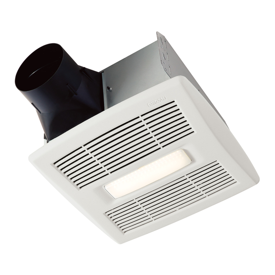
Summary of Contents for NuTone inVent AE80SL
- Page 1 Ventilador/Lámpara con sensor de humedad Model numbers: AE80SL Números de modelo: AE110SL INSTALLATION AND USE & CARE INSTRUCTIONS INSTRUCCIONES PARA INSTALACIÓN, USO Y CUIDADO English - See page 2 Español - Consulte la página 9 © 2016 Broan-NuTone LLC 99045716A...
- Page 2 Please visit our website - www.broan.com to register this product and to view installation tips and videos. Installer: Leave this manual with the homeowner. READ AND SAVE THESE INSTRUCTIONS WARNING CAUTION To reduce the risk of fire, electric • For general ventilating use only. Do not shock, or injury to persons, observe the use to exhaust hazardous or explosive following:...
-
Page 3: Cleaning And Maintenance
CLEANING & MAINTENANCE For quiet and efficient operation, long life, and SENSOR CLEANING attractive appearance - lower or remove grille The humidity sensor is mounted in the control housing. The and vacuum interior of unit with the dusting brush sensor will operate most reliably when cleaned occasionally attachment. -
Page 4: All Installations
ALL INSTALLATIONS Start here. 1. Remove blower and all packing material from fan WARNING housing. • Disconnect the electrical power supply and lock out the service panel. COOKING AREA Do not install above or inside this area. NOT FOR USE IN Cooking A COOKING AREA. -
Page 5: New Construction
NEW CONSTRUCTION 5. Connect 4-in. round duct. For Retrofit Installation - Skip to Page 6. 3. Attach damper/duct connector to fan housing. Push connector through opening from inside of housing. Engage tabs and secure with screw from parts bag. 6. Connect wiring. Bend tab to expose desired access hole. -
Page 6: Install Blower
7. Install blower. Push grille up against ceiling. Re-install blower. Secure blower with 2 screws from parts bag and plug blower into black receptacle. Plug in humidity- sensing control. CAUTION • Make sure that the wiring inside of the housing does not interfere with re-installation of the blower. - Page 7 5. Connect wiring. 7. Connect 4-in. round duct. Bend tab to expose desired access hole. Connect Pull existing ducting through housing discharge power cable to housing with appropriate UL approved opening. connector. Connect wires per diagram on page 8. Re- install wiring panel and secure with screw from parts Attach and tape ducting to duct connector.
-
Page 8: Wiring Diagrams
WIRING DIAGRAMS WIRING OPTION #1 WIRING OPTION #2 • When first switch (1) is ON, fan will operate auto- • When first switch (1) is ON, fan will operate auto- matically, based on room humidity conditions. matically based on room humidity conditions. •... - Page 9 Visite nuestro sitio web: www.broan.com para registrar este producto y ver consejos y videos para la instalación. Aviso al instalador: Deje este manual con el dueño de la casa. LEA Y CONSERVE ESTAS INSTRUCCIONES ADVERTENCIA PRECAUCIÓN Para reducir el riesgo de incendios, descargas •...
-
Page 10: Limpieza Y Mantenimiento
LIMPIEZA Y MANTENIMIENTO Para lograr un funcionamiento silencioso y eficiente, LIMPIEZA DEL SENSOR una larga vida y la apariencia atractiva del producto, El sensor de humedad está montado en la cubierta del con- baje o retire la rejilla y aspire el interior de la unidad trol. - Page 11 1. Retire el soplador y todo el TODAS LAS INSTALACIONES material de empaque de la Comience aquí. cubierta del ventilador. ADVERTENCIA • Desconectar la fuente de alimentación eléctrica y bloquee el panel de servicio. ÁREA DE COCINA No instalar el producto sobre esta área ni dentro de ella.
- Page 12 CONSTRUCCIÓN NUEVA 5. Conecte el conducto redondo de Para instalaciones de conversión: pase a la página 13. 4 pulg. (10 cm). 3. Acople el conector del regulador de tiro/conducto a la cubierta del ventilador. Empuje el conector a través de la abertura desde el interior de la cubierta.
- Page 13 Empuje la rejilla 7. Instale el soplador. contra el cielo Vuelva a instalar el soplador. Fíjelo con 2 tornillos de la bolsa raso. de piezas y conecte el soplador en el receptáculo negro. Enchufe el control de humedad con sensor. PRECAUCIÓN •...
- Page 14 5. Conecte el cableado. 7. Conecte el conducto redondo de 4 pulg. (10 cm). Doble la lengüeta para exponer el orificio de acceso deseado. Conecte el cable eléctrico a la cubierta con Jale el conducto existente a través de la abertura una conexión apropiada aprobada por UL.
-
Page 15: Diagramas De Cableado
DIAGRAMAS DE CABLEADO OPCIÓN DE CONEXIÓN # 1 OPCIÓN DE CONEXIÓN # 2 • Cuando primer interruptor (1) está en ON, el • Cuando primer interruptor (1) está en ON, ventila- ventilador funcionará automáticamente, en base a dor funcionará automáticamente en función de las las condiciones de humedad ambiente. - Page 16 Limited Warranty Warranty Period and Exclusions: Broan-NuTone LLC (the “Company”) warrants to the original consumer purchaser of its product (“you”) that the product (the “Product”) will be free from material defects in the Product or its workmanship for a period of three (3) years from the date of original purchase.


