Advertisement
Quick Links
7" and 10" T3 Series In-Wall Touch Screen
Installation Guide
Supported models
• C4-WALL7-BL
7" T3-7 In-Wall Touch Screen, Black
• C4-WALL7-WH
7" T3-7 In-Wall Touch Screen, White
• C4-WALL10-BL
10" T3-10 In-Wall Touch Screen, Black
• C4-WALL10-WH
10" T3-10 In-Wall Touch Screen, White
Introduction
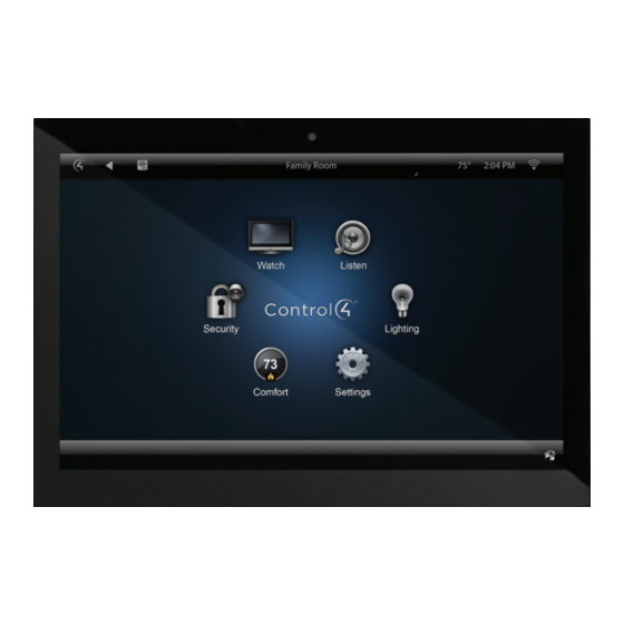
The Control4® T3-7 (7") and T3-10 (10") In-Wall Touch Screens
offer complete system control in an elegant and compact design.
The touch screens are equipped with a full capacitive screen,
audio and video Intercom (with the built-in camera) using SIP,
and more.
This touch screen works great in either new construction or
retrofit installations. For power and network connectivity, choose
from three options:
• Ethernet with PoE—The Ethernet network connection is
provided through the PoE Injector. No additional wiring is
needed.
• Ethernet with AC—Connect the touch screen to one of the
RJ-45 LAN ports on the gateway/router using the RJ-45
Ethernet cable. AC power is used to power the touch screen.
• WiFi with AC—The internal WiFi will communicate with the
LAN's WAP. If the LAN has a WAP set up, no additional
network wiring is needed. AC power is used to power the
touch screen.
Note: 802.11b is not recommended for Video Intercom.
We recommend using Wireless-N. See "Specifications"
and "Power and Network Installation Options" for more
information.
Box contents
• 7" or 10" T3-7/T3-10 In-Wall Touch Screen
• Power box (to power the touch screen) (005-00065)
• Two screws (to attach the power box)
• Touch Screen removal tool
• Four adhesive-backed foam pads
• Warranty card
1 1
Accessories available for purchase
• PoE. Control4 Power over Ethernet Injector, sold separately
(AC-POE1-B).
• Back box options (sold separately)—Metal and plastic, for
new construction or retrofit installations.
• 7" and 10" In-Wall Touch Screen Back Box Kits - New
Construction
• 7" and 10" In-Wall Touch Screens Wall Box, New
Construction, Plastic (C4-NWB57C-P)
• 7" and 10" In-Wall Touch Screens Wall Box, New
Construction, Metal (C4-NWB57C-M)
• 7" and 10" In-Wall Touch Screen Back Box Kit - Retrofit
• 7" and 10" In-Wall Touch Screens Wall Box, Retrofit,
Plastic (C4-RWB57C-P)
• 7" and 10" In-Wall Touch Screens Wall Box, Retrofit,
Metal (C4-RWB57C-M)
For back box installation details, see:
• 7" or 10" In-Wall Touch Screen Wall Box Installation
Guide-New Construction
• 7", or 10" In-Wall Touch Screen Wall Box Installation
Guide-Retrofit
Advertisement

Related Manuals for Control 4 7 Series


Summary of Contents for Control 4 7 Series
- Page 1 7" and 10" T3 Series In-Wall Touch Screen Installation Guide Supported models Accessories available for purchase • C4-WALL7-BL 7" T3-7 In-Wall Touch Screen, Black • PoE. Control4 Power over Ethernet Injector, sold separately (AC-POE1-B). • C4-WALL7-WH 7" T3-7 In-Wall Touch Screen, White •...
-
Page 2: Specifications And Requirements
Warnings Specifications and requirements Warning! The touch screen must be protected by an Specifications external circuit breaker or a fuse rated at 6A maximum when used in Europe. C4-WALL7-BL, C4-WALL7-WH, C4-WALL10-BL, Model Numbers AVERTISSEMENT ! Pour réduire le risque du feu ou de C4-WALL10-WH choc électrique, n’exposez pas cet appareil à... -
Page 3: Front View
Front view Touch screen placement Figure 1: Front view Place the touch screen in a convenient location at eye level, typically near the entrance of the room, approximately 57 to 61 inches (145 cm to 155 cm) from the floor (Figure 3). Note: Consider the camera on the panel and the height of the people in the home who will use the camera for Video Intercom. - Page 4 Option 1: Ethernet connection with PoE Wireless Network Limitations: Many WiFi Access Points handle Multicasts (WiFi simultaneously sent to multiple PoE supplies DC power on the Ethernet cable using a PoE devices, for example, when the touch screen broadcasts Injector (model #AC-POE1-B) or a third-party PoE solution to video to all stations) by slowing down transmission provide the touch screen with power and a network connection.
- Page 5 Figure 7: Insert Ethernet cable into power box Figure 9: Connect AC power Neutral (N) Line (L) 5 Go to “Attach the power box and touch screen” below. Connecting standard Ethernet 4 Cap the ground wire from the wall if you are using a plastic To connect to a wired network: back box.
- Page 6 Figure 11: Attach ribbon cable to the power box 5 Tap OK. Add and configure in Composer Pro After the touch screen is installed and appears on the home network, use Composer Pro to add it to the Control4 system and configure it.
-
Page 7: Troubleshooting
Troubleshooting Regulatory/Safety Information To review regulatory information for your particular Control4 Boot up time products, see the information located on the Control4 website at: ctrl4.co/reg When the device is booting up, it may take 30 seconds or longer before the Green LED turns on. When it turns on, it blinks slowly for a time and then turns off. - Page 8 Regulatory Compliance & Safety Information for Contol4 Model C4-WALL7-XX & C4- WALL10-XX. Electrical Safety Advisory Sécurité électrique consultatif Important Safety Information Informations de sécurité importantes Read the safety instructions before using this product. Lisez les consignes de sécurité avant d'utiliser ce produit. 1.
- Page 9 deux lames et une troisième broche de terre. La lame large ou la troisième broche est fournie pour votre sécurité. Si la fiche fournie ne s'adapte pas à votre prise, consultez un électricien pour le remplacement de la prise obsolète. 10.
- Page 10 16. Pour couper entièrement l'alimentation appareil de l'alimentation secteur, éteignez le disjoncteur. Pour rétablir le courant, mettez le disjoncteur après les consignes de sécurité et des lignes directrices. 17. This product relies on the buildings installation for short-circuit (overcurrent) protection. Ensure that the protective device is rated not greater than: 20A.
- Page 11 Warning!: To reduce the risk of electrical shock, do not expose this apparatus to rain or moisture AVERTISSEMENT! Pour réduire le risque de choc électrique, n'exposez pas cet appareil à la pluie ou à l'humidité. Save these instructions Conservez ces instructions Compliance of this equipment is confirmed by the following label that is placed on the equipment: Conformité...
- Page 12 être déterminé en mettant l'équipement hors et sous tension, l'utilisateur est encouragé à essayer de corriger l'interférence par une ou plusieurs des mesures suivantes: Réorienter ou déplacer l'antenne de réception. Augmenter la distance entre l'équipement et le récepteur. ...
- Page 13 indiqués ci-dessous sont pour le module WiFi qui a été certifiée en tant que Approbation limitée modulaire. FCC ID: R33C4LGWM IC: 7848A-C4LGWM L'équipement d'utilisateur final qui contient le module WiFi certifiée sont marqués par le suivant à l'extérieur de l'objet: Contient ID FCC: R33C4LGWM Contient IC: 7848A-C4LGWM Cet équipement doit être installé...
- Page 14 European Compliance Conformity of the equipment with the guidelines below is attested by the application of the CE mark. CE Declaration of Conformity Manufacturer’s Name: CONTROL4 CORPORATION Manufacturer’s Address: 11734 S. ELECTION ROAD SUITE 200 SALT LAKE CITY UT 84020 USA EU Representative Name: CONTROL4 EMEA LIMITED EU Representative Address: UNIT3, GREEN PARK BUSINESS CENTRE...
- Page 15 Recycling Control4 understands that a commitment to the environment is essential for a health life and sustainable growth for future generations. We are committed to supporting the environmental standards, laws, and directives that have been put in place by various communities and countries that deal with concerns for the environment.
- Page 16 Regulatory Compliance & Safety Information for Contol4 Model C4-WALL7-XX & C4- WALL10-XX. Electrical Safety Advisory Sécurité électrique consultatif Important Safety Information Informations de sécurité importantes Read the safety instructions before using this product. Lisez les consignes de sécurité avant d'utiliser ce produit. 1.
- Page 17 deux lames et une troisième broche de terre. La lame large ou la troisième broche est fournie pour votre sécurité. Si la fiche fournie ne s'adapte pas à votre prise, consultez un électricien pour le remplacement de la prise obsolète. 10.
- Page 18 16. Pour couper entièrement l'alimentation appareil de l'alimentation secteur, éteignez le disjoncteur. Pour rétablir le courant, mettez le disjoncteur après les consignes de sécurité et des lignes directrices. 17. This product relies on the buildings installation for short-circuit (overcurrent) protection. Ensure that the protective device is rated not greater than: 20A.
- Page 19 Warning!: To reduce the risk of electrical shock, do not expose this apparatus to rain or moisture AVERTISSEMENT! Pour réduire le risque de choc électrique, n'exposez pas cet appareil à la pluie ou à l'humidité. Save these instructions Conservez ces instructions Compliance of this equipment is confirmed by the following label that is placed on the equipment: Conformité...
- Page 20 être déterminé en mettant l'équipement hors et sous tension, l'utilisateur est encouragé à essayer de corriger l'interférence par une ou plusieurs des mesures suivantes: • Réorienter ou déplacer l'antenne de réception. • Augmenter la distance entre l'équipement et le récepteur. •...
- Page 21 indiqués ci-dessous sont pour le module WiFi qui a été certifiée en tant que Approbation limitée modulaire. FCC ID: R33C4WALL5G IC: 7848A-C4LGWM Cet équipement doit être installé par des professionnels qualifiés ou entrepreneurs conformément aux normes FCC partie 15.203 & IC RSS-210, Exigences d'antenne. Ne pas utiliser une antenne autre que celui fourni avec l'appareil.
- Page 22 European Compliance Conformity of the equipment with the guidelines below is attested by the application of the CE mark. CE Declaration of Conformity Manufacturer’s Name: CONTROL4 CORPORATION Manufacturer’s Address: 11734 S. ELECTION ROAD SUITE 200 SALT LAKE CITY UT 84020 USA EU Representative Name: CONTROL4 EMEA LIMITED EU Representative Address: UNIT3, GREEN PARK BUSINESS CENTRE...
- Page 23 Recycling Control4 understands that a commitment to the environment is essential for a health life and sustainable growth for future generations. We are committed to supporting the environmental standards, laws, and directives that have been put in place by various communities and countries that deal with concerns for the environment.