
Related Manuals for Greenlee 853


Summary of Contents for Greenlee 853
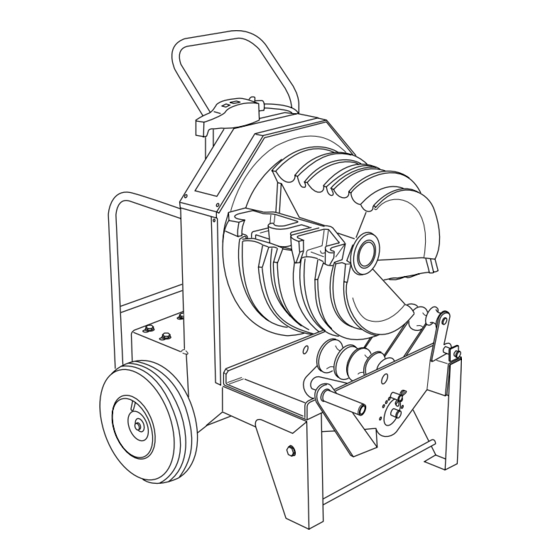
- Page 1 INSTRUCTION MANUAL QUAD BENDER™ Read and understand all of the instructions and safety information in this manual before operating or servicing this tool. 999 3876.6 © 2001 Greenlee Textron IM 1527 REV 1 4/01...
-
Page 2: Table Of Contents
Maintenance ... 23 Troubleshooting ... 24 Description The Greenlee 853 Quad Bender™ is intended to bend 1" to 2" EMT, IMC, rigid steel, and rigid aluminum conduit from 0 through 90 degrees. The Greenlee 853 Quad Bender™ is protected by U.S. -
Page 3: Important Safety Information
Failure to observe this warning will result in severe injury or death. Greenlee Textron / Subsidiary of Textron Inc. Electric shock hazard: • Connect the power cord to a 120 volt, 20 amp receptacle on a ground fault protected circuit only. - Page 4 Failure to observe this warning can result in severe injury. Greenlee Textron / Subsidiary of Textron Inc. Do not use as a step or ladder. • Conduit moves rapidly as it is bent. The path of the conduit must be clear of obstructions.
-
Page 5: Grounding Instructions
Failure to observe these warning can result in severe injury or death. Greenlee Textron / Subsidiary of Textron Inc. This tool must be grounded. In the event of a malfunc- tion or breakdown, an electrical ground provides a path of least resistance for the electric current. -
Page 6: Identification
Temperature ... –20 C to 49 C (–5 F to 120 F) Relative Humidity ... 0 to 98% Capacity ... 1" to 2" EMT, IMC and Rigid Steel and Rigid Aluminum Conduit Greenlee Textron / Subsidiary of Textron Inc. 853 Quad Bender™ 7. Bending Instructions Decal 8. -
Page 7: Identification
853 Quad Bender™ Identification (cont’d) Roller Support Assembly (500 7267.6) Bending Shoe (500 7271.4) Greenlee Textron / Subsidiary of Textron Inc. 4455 Boeing Dr., Rockford, IL 61109-2988 815/397-7070... -
Page 8: Setup
Roller Support Assembly Installed Install pin Greenlee Textron / Subsidiary of Textron Inc. 2. Slide the bending shoe onto the shaft of the main sprocket, as shown. Align the four drive studs on the back of the shoe with the four holes in the main sprocket. -
Page 9: Operation
Loose clothing can get caught in moving parts. Failure to observe this warning can result in severe injury or death. Greenlee Textron / Subsidiary of Textron Inc. BENDING CONDUIT 1. Plug the cord into an appropriate receptacle. See Grounding Instructions. - Page 10 Release the switch as you approach the desired angle of bend. d. Press BEND momentarily until the bend is complete. Greenlee Textron / Subsidiary of Textron Inc. 1-1/4" to 2" Steel Rigid Conduit: a. Press and hold BEND. b. Release the switch as you approach the desired angle of bend.
- Page 11 Roller Support Assembly (see p. 6) to align the center- line of the roller with the centerline of the shoe groove. Retighten the locator screws. Adjusting the Roller Support Location R.H. Locator Screw Greenlee Textron / Subsidiary of Textron Inc. 4455 Boeing Dr., Rockford, IL 61109-2988 815/397-7070...
-
Page 12: Illustrated Bending Glossary
853 Quad Bender™ Illustrated Bending Glossary Offset Height Greenlee Textron / Subsidiary of Textron Inc. back-to-back bend — any U-shaped bend formed by two parallel 90 bends with a straight section of conduit or pipe between the bends. center-to-center distance — the distance between the successive bends that make up an offset or a three-bend saddle. -
Page 13: Bending Instructions
Compensate by overbending as shown in the Scale Reading Table. The shoe bends to 90 maximum. STUB LENGTH MARK 2 MARK 1 DEDUCT MARK 2 Greenlee Textron / Subsidiary of Textron Inc. Deduct Table SIZE STEEL RIGID 11-7/8 DEDUCT 11-7/8 11-7/8 ALUM. - Page 14 Without removing the conduit from the bender, rotate the conduit 180 . Make the second bend. LENGTH MARK 1 CENTER TO CENTER DISTANCE LENGTH HEIGHT OBSTRUCTION Greenlee Textron / Subsidiary of Textron Inc. Offset Table Finished Angle OFFSET CENTER CONDUIT SIZE CENTER 1-1/4...
- Page 15 5. Bend the conduit. HEIGHT ANGLE MARK Greenlee Textron / Subsidiary of Textron Inc. OFFSETS An offset is used to route the conduit around an obstruc- tion. To make an offset, two equal bends are required. The distance between the two bends is the center-to- center distance.
- Page 16 ANGLE LENGTH – Z MARK 1 MARK 2 Greenlee Textron / Subsidiary of Textron Inc. THREE-BEND SADDLE 1. Select the size and type of conduit. Measure the height of the obstruction and the distance from the end of the conduit to the center (LENGTH TO CENTER) of the bend.
- Page 17 L2 + STRAIGHT SECTION LENGTH – Z MARK 1 MARK 2 Greenlee Textron / Subsidiary of Textron Inc. U-BENDS 1. Select the size and type of conduit. Determine the LENGTH and the HEIGHT. 2. Find the table that corresponds to the size and type of conduit selected in Step 1.
-
Page 18: Bending Tables
22.5 22.5 22.5 22.5 MINIMUM H = 3.21 MINIMUM H = 4.78 MINIMUM H = 8.52 MINIMUM H = 12.85 MINIMUM H = 22.04 Greenlee Textron / Subsidiary of Textron Inc. 2" 4" 6" 8" 10" 0.49 8.22 15.94 23.67 31.40... - Page 19 MINIMUM H = 2.25 22.5 22.5 22.5 22.5 MINIMUM H = 3.81 MINIMUM H = 5.64 MINIMUM H = 9.95 MINIMUM H = 14.89 MINIMUM H= 25.28 Greenlee Textron / Subsidiary of Textron Inc. 2" 4" 6" 8" 10" 5.20 12.93 20.65 28.38 7.71...
- Page 20 22.5 22.5 22.5 22.5 MINIMUM H = 3.25 MINIMUM H = 4.83 MINIMUM H = 8.59 MINIMUM H = 12.90 MINIMUM H = 22.04 Greenlee Textron / Subsidiary of Textron Inc. 2" 4" 6" 8" 10" 0.19 7.91 15.64 23.37 31.09...
- Page 21 22.5 22.5 22.5 22.5 MINIMUM H = 3.78 MINIMUM H = 5.58 MINIMUM H = 9.81 MINIMUM H = 14.64 MINIMUM H = 24.27 Greenlee Textron / Subsidiary of Textron Inc. 2" 4" 6" 8" 10" 4.75 12.48 20.21 27.93 7.71...
-
Page 22: Handle Removal And Replacement
853 Quad Bender™ Handle Removal and Replacement The handle of the 853 is removable. This feature is convenient when performing complex bending, and makes it easy to replace a damaged handle. Removal 1. Place the bender in the upright position. -
Page 23: Maintenance
4. Slide the reductor in slotted mounting holes to the retension chain. Set tension with the eccentric cam. Greenlee Textron / Subsidiary of Textron Inc. With the eight reductor mounting bolts loose, rotate the eccentric cam with a 1/2" square drive to tension the chain. -
Page 24: Troubleshooting
Too little squeeze on 1-1/4", 1-1/2" or 2" EMT, IMC or Rigid Aluminum conduit. Unusual conduit characteristics. Greenlee Textron / Subsidiary of Textron Inc. 4455 Boeing Drive, Rockford, IL 61109-2988 USA Canada Fax: 800/524-2853 POSSIBLE REMEDY Check supply voltage circuit operation.