
Related Manuals for Gigabyte GA-945GCM-S2C


Summary of Contents for Gigabyte GA-945GCM-S2C
- Page 1 GA-945GCM-S2L/ GA-945GCM-S2C LGA775 socket motherboard for Intel Core processor family/ ® Intel Pentium processor family/Intel Celeron processor family ® ® ® ® User's Manual Rev. 1007 12ME-945GCMS2-1007R...
-
Page 3: Identifying Your Motherboard Revision
GIGABYTE's prior written permission. Documentation Classifications In order to assist in the use of this product, GIGABYTE provides the following types of documentations: For detailed product information, carefully read the User's Manual. For instructions on how to use GIGABYTE's unique features, read or download the information on/from the Support\Motherboard\Technology Guide page on our website. -
Page 4: Table Of Contents
Box Contents ... 6 Optional Items... 6 GA-945GCM-S2L/GA-945GCM-S2C Motherboard Layout ... 7 Block Diagram... 8 Chapter 1 Hardware Installation ... 9 Installation Precautions ... 9 Product Specifications ... 10 Installing the CPU and CPU Cooler ... 13 1-3-1 Installing the CPU ... 13 1-3-2 Installing the CPU Cooler ... - Page 5 Chapter 3 Drivers Installation ... 53 Installing Chipset Drivers ... 53 Software Applications ... 54 Driver CD Information ... 54 Hardware Information ... 55 Contact Us ... 55 Chapter 4 Unique Features ... 57 Xpress Recovery2 ... 57 BIOS Update Utilities ... 62 4-2-1 Updating the BIOS with the Q-Flash Utility ...
-
Page 6: Box Contents
Box Contents GA-945GCM-S2L or GA-945GCM-S2C motherboard Motherboard driver disk User's Manual Quick Installation Guide One IDE cable and one floppy disk drive cable Two SATA 3Gb/s cables I/O Shield • The box contents above are for reference only and the actual items shall depend on product package you obtain. -
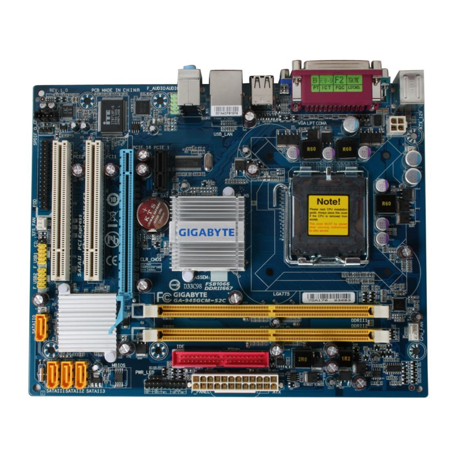
Page 7: Ga-945Gcm-S2L/Ga-945Gcm-S2C Motherboard Layout
GA-945GCM-S2L/GA-945GCM-S2C Motherboard Layout KB_MS ATX_12V R_USB AUDIO F_AUDIO RTL8111C PCIE_1 RTL8101E PCIE_16 IT8718 PCI1 CODEC PCI2 Only for GA-945GCM-S2L. Only for GA-945GCM-S2C. LGA775 Intel 945GC ® CLR_CMOS Intel SYS_FAN F_USB1 F_USB2 - 7 - CPU_FAN MBIOS ICH7 ® SATAII3 SATAII2... -
Page 8: Block Diagram
PCI CLK (33 MHz) Only for GA-945GCM-S2L. Only for GA-945GCM-S2C. (Note 1) Enable use of a Core FSB 1333 MHz Core (Note 2) Use of a 1066/800 MHz FSB CPU is required if you wish to install DDR2 667 MHz memory. -
Page 9: Chapter 1 Hardware Installation
Chapter 1 Hardware Installation Installation Precautions The motherboard contains numerous delicate electronic circuits and components which can become damaged as a result of electrostatic discharge (ESD). Prior to installation, carefully read the user's manual and follow these procedures: Prior to installation, do not remove or break motherboard S/N (Serial Number) sticker or •... -
Page 10: Product Specifications
Product Specifications Support for an Intel Intel Intel Intel (Go to GIGABYTE's website for the latest CPU support list.) Support for Intel L2 cache varies with CPU Front Side Bus 1333 Chipset North Bridge: Intel South Bridge: Intel Memory 2 x 1.8V DDR2 DIMM sockets supporting up to 4 GB of system memory... - Page 11 Internal Connectors 1 x 24-pin ATX main power connector 1 x 4-pin ATX 12V power connector 1 x floppy disk drive connector 1 x IDE connector 4 x SATA 3Gb/s connectors 1 x CPU fan header 1 x system fan header 1 x front panel header 1 x front panel audio header 1 x CD In connector...
- Page 12 Unique Features Support for @BIOS Support for Download Center Support for Q-Flash Support for EasyTune Support for Xpress Install Support for Xpress Recovery2 Support for Virtual Dual BIOS Bundled Software Norton Internet Security (OEM version) Operating System Support for Microsoft Form Factor Micro ATX form factor;...
-
Page 13: Installing The Cpu And Cpu Cooler
Read the following guidelines before you begin to install the CPU: • Make sure that the motherboard supports the CPU. (Go to GIGABYTE's website for the latest CPU support list.) • Always turn off the computer and unplug the power cord from the power outlet before installing the CPU to prevent hardware damage. - Page 14 B. Follow the steps below to correctly install the CPU into the motherboard CPU socket. Before installing the CPU, make sure to turn off the computer and unplug the power cord from the power outlet to prevent damage to the CPU. CPU Socket Lever Step 1: Completely raise the CPU socket lever.
-
Page 15: Installing The Cpu Cooler
1-3-2 Installing the CPU Cooler Follow the steps below to correctly install the CPU cooler on the motherboard. (The following procedure uses Intel boxed cooler as the example cooler.) ® Step 1: Apply an even and thin layer of thermal grease on the surface of the installed CPU. -
Page 16: Installing The Memory
• Make sure that the motherboard supports the memory. It is recommended that memory of the same capacity, brand, speed, and chips be used. (Go to GIGABYTE's website for the latest memory support list.) • Always turn off the computer and unplug the power cord from the power outlet before installing the memory to prevent hardware damage. -
Page 17: Installing A Memory
1-4-2 Installing a Memory Before installing a memory module , make sure to turn off the computer and unplug the power cord from the power outlet to prevent damage to the memory module. DDR2 DIMMs are not compatible to DDR DIMMs. Be sure to install DDR2 DIMMs on this motherboard. -
Page 18: Installing An Expansion Card
Installing an Expansion Card Read the following guidelines before you begin to install an expansion card: • Make sure the motherboard supports the expansion card. Carefully read the manual that came with your expansion card. • Always turn off the computer and unplug the power cord from the power outlet before installing an expansion card to prevent hardware damage. -
Page 19: Back Panel Connectors
Back Panel Connectors PS/2 Keyboard and PS/2 Mouse Port Use the upper port (green) to connect a PS/2 mouse and the lower port (purple) to connect a PS/2 keyboard. Parallel Port Use the parallel port to connect devices such as a printer, scanner and etc. The parallel port is also called a printer port. - Page 20 Mic In Jack (Pink) The default Mic in jack. Microphones must be connected to this jack. Refer to the instructions on setting up a 2/4/5.1-channel audio configuration in Chapter 5, "Configuring 2/4/5.1-Channel Audio." Only for GA-945GCM-S2C. GA-945GCM-S2L/S2C Motherboard Connection/Speed LED: State...
-
Page 21: Internal Connectors
Internal Connectors ATX_12V CPU_FAN SYS_FAN SATAII0 / 1 / 2 / 3 PWR_LED Read the following guidelines before connecting external devices: • First make sure your devices are compliant with the connectors you wish to connect. • Before installing the devices, be sure to turn off the devices and your computer. Unplug the power cord from the power outlet to prevent damage to the devices. - Page 22 1/2) ATX_12V/ATX (2x2 12V Power Connector and 2x12 Main Power Connector) With the use of the power connector, the power supply can supply enough stable power to all the components on the motherboard. Before connecting the power connector, first make sure the power supply is turned off and all devices are properly installed.
- Page 23 3/4) CPU_FAN/SYS_FAN (Fan Headers) The motherboard has a 4-pin CPU fan header (CPU_FAN) and a 3-pin system fan header (SYS_FAN). Each fan header supplies a +12V power voltage and possesses a foolproof insertion design. When connecting a fan cable, be sure to connect it in the correct orientation. Most fans are designed with color-coded power connector wires.
- Page 24 6) IDE (IDE Connector) The IDE connector supports up to two IDE devices such as hard drives and optical drives. Before attaching the IDE cable, locate the foolproof groove on the connector. If you wish to connect two IDE devices, remember to set the jumpers and the cabling according to the role of the IDE devices (for example, master or slave).
-
Page 25: Battery
8) PWR_LED (System Power LED Header) This header can be used to connect a system power LED on the chassis to indicate system power status. The LED is on when the system is operating. The LED keeps blinking when the system is in S1 sleep state. -
Page 26: F_Panel
10) F_PANEL (Front Panel Header) Connect the power switch, reset switch, speaker and system status indicator on the chassis front panel to this header according to the pin assignments below. Note the positive and negative pins before connecting the cables. •... -
Page 27: Cd In Connector
11) F_AUDIO (Front Panel Audio Header) The front panel audio header supports Intel High Definition audio (HD) and AC'97 audio. You may connect your chassis front panel audio module to this header. Make sure the wire assignments of the module connector match the pin assignments of the motherboard header. Incorrect connection between the module connector and the motherboard header will make the device unable to work or even damage it. -
Page 28: Usb Headers
13) SPDIF_O (S/PDIF Out Header) This header supports digital S/PDIF out. Via an optional S/PDIF out cable, this header can connect to an audio device that supports digital audio in. For purchasing the optional S/PDIF out cable, please contact the local dealer. Pin 1 (the red wire) of the S/PDIF out cable must align with pin 1 of the SPDIF_O header. -
Page 29: Chassis Intrusion Header
15) CLR_CMOS (Clearing CMOS Jumper) Use this jumper to clear the CMOS values (e.g. date information and BIOS configurations) and reset the CMOS values to factory defaults. To clear the CMOS values, place a jumper cap on the two pins to temporarily short the two pins or use a metal object like a screwdriver to touch the two pins for a few seconds. - Page 30 GA-945GCM-S2L/S2C Motherboard - 30 -...
-
Page 31: Chapter 2 Bios Setup
To see more advanced BIOS Setup menu options, you can press <Ctrl> + <F1> in the main menu of the BIOS Setup program. To upgrade the BIOS, use either the GIGABYTE Q-Flash or @BIOS utility. Q-Flash allows the user to quickly and easily upgrade or back up BIOS without entering the •... -
Page 32: Startup Screen
Startup Screen The following screen may appear when the computer boots. Award Modular BIOS v6.00PG, An Energy Star Ally Copyright (C) 1984-2007, Award Software, Inc. Intel I945 BIOS for 945GCM-S2L E10 Motherboard Model BIOS Version <DEL>: BIOS Setup/Q-Flash <F9>: XpressRecovery2 <F12>: Boot Menu <End>: Qflash 08/01/2007-I945-6A89HG0IC-00 Function Keys: <DEL>... -
Page 33: The Main Menu
The Main Menu Once you enter the BIOS Setup program, the Main Menu (as shown below) appears on the screen. Use arrow keys to move among the items and press <Enter> to accept or enter a sub-menu. (Sample BIOS Version: GA-945GCM-S2L E10) CMOS Setup Utility-Copyright (C) 1984-2007 Award Software Standard CMOS Features Advanced BIOS Features... - Page 34 Standard CMOS Features Use this menu to configure the system time and date, hard drive types, floppy disk drive types, and the type of errors that stop the system boot, etc. Advanced BIOS Features Use this menu to configure the device boot order, advanced features available on the CPU, and the primary display adapter.
-
Page 35: Standard Cmos Features
Standard CMOS Features CMOS Setup Utility-Copyright (C) 1984-2007 Award Software Date (mm:dd:yy) Time (hh:mm:ss) IDE Channel 0 Master IDE Channel 0 Slave IDE Channel 2 Master IDE Channel 2 Slave IDE Channel 3 Master IDE Channel 3 Slave Drive A Floppy 3 Mode Support Halt On Base Memory... - Page 36 The following fields display your hard drive specifications. If you wish to enter the parameters manually, refer to the information on the hard drive. Capacity Approximate capacity of the currently installed hard drive. Cylinder Number of cylinders. Head Number of heads. Precomp Write precompensation cylinder.
-
Page 37: Advanced Bios Features
Advanced BIOS Features CMOS Setup Utility-Copyright (C) 1984-2007 Award Software Hard Disk Boot Priority First Boot Device Second Boot Device Third Boot Device Password Check HDD S.M.A.R.T. Capability CPU Hyper-Threading (Note) Limit CPUID Max. to 3 (Note) No-Execute Memory Protect CPU Enhanced Halt (C1E) CPU Thermal Monitor 2(TM2) CPU EIST Function... - Page 38 Limit CPUID Max. to 3 Allows you to determine whether to limit CPUID maximum value. Set this item to Disabled for Windows XP operating system; set this item to Enabled for legacy operating system such as Windows NT4.0. (Default: Disabled) No-Execute Memory Protect Enables or disables Intel the computer, reducing exposure to viruses and malicious buffer overflow attacks when working...
-
Page 39: Integrated Peripherals
Integrated Peripherals CMOS Setup Utility-Copyright (C) 1984-2007 Award Software On-Chip Primary PCI IDE On-Chip SATA Mode x PATA IDE Set to SATA Port 0/2 Set to SATA Port 1/3 Set to USB Controller USB 2.0 Controller USB Keyboard Support USB Mouse Support Legacy USB storage detect Azalia Codec Onboard H/W LAN... -
Page 40: Usb Controller
SATA Port 1/3 Set to This value is dependent on the On-Chip SATA Mode and PATA IDE Set to settings. When PATA IDE Set to is configured to Ch. 0 Master/Slave, this option will be automatically set to Ch. 1 Master/Slave. USB Controller Enables or disables the integrated USB controller. - Page 41 SMART LAN (LAN Cable Diagnostic Function) CMOS Setup Utility-Copyright (C) 1984-2007 Award Software Start detecting at Port... Pair1-2 Status = Open Pair3-6 Status = Open Pair4-5 Status = Open Pair7-8 Status = Open : Move Enter: Select F5: Previous Values This motherboard incorporates cable diagnostic feature designed to detect the status of the attached LAN cable.
- Page 42 Onboard LAN Boot ROM Allows you to decide whether to activate the boot ROM integrated with the onboard LAN chip. (Default: Disabled) Onboard Serial Port 1 Enables or disables the first serial port and specifies its base I/O address and corresponding interrupt.
-
Page 43: Power Management Setup
Power Management Setup CMOS Setup Utility-Copyright (C) 1984-2007 Award Software ACPI Suspend Type Soft-Off by PWR-BTTN PME Event Wake Up Power On by Ring Resume by Alarm x Date (of Month) Alarm x Time (hh:mm:ss) Alarm HPET Support (Note) (Note) HPET Mode Power On By Mouse Power On By Keyboard... - Page 44 Resume by Alarm Determines whether to power on the system at a desired time. (Default: Disabled) If enabled, set the date and time as following: Date (of Month) Alarm : Turn on the system at a specific time on each day or on a specific day in a month.
-
Page 45: Pnp/Pci Configurations
PnP/PCI Configurations CMOS Setup Utility-Copyright (C) 1984-2007 Award Software PCI1 IRQ Assignment PCI2 IRQ Assignment : Move Enter: Select F5: Previous Values PCI1 IRQ Assignment Auto 3,4,5,7,9,10,11,12,14,15 PCI2 IRQ Assignment Auto 3,4,5,7,9,10,11,12,14,15 PnP/PCI Configurations [Auto] [Auto] +/-/PU/PD: Value F10: Save F6: Fail-Safe Defaults BIOS auto-assigns IRQ to the first PCI slot. -
Page 46: Pc Health Status
PC Health Status CMOS Setup Utility-Copyright (C) 1984-2007 Award Software Reset Case Open Status Case Opened Vcore DDR18V +3.3V +12V Current CPU Temperature Current CPU FAN Speed Current SYSTEM FAN Speed CPU Warning Temperature CPU FAN Fail Warning SYSTEM FAN Fail Warning CPU Smart FAN Control : Move Enter: Select... - Page 47 CPU Smart FAN Control Enables or disables the CPU fan speed control function. Enabled allows the CPU fan to run at different speed according to the CPU temperature. You can adjust the fan speed with EasyTune based on system requirements. If disabled, CPU fan runs at full speed. (Default: Enabled) - 47 - BIOS Setup...
-
Page 48: Frequency/Voltage Control
Frequency/Voltage Control CMOS Setup Utility-Copyright (C) 1984-2007 Award Software (Note) CPU Clock Ratio O.C FSB1333 Core. 2 CPU CPU Host Clock Control x CPU Host Frequency(Mhz) PCI Express Frequency (Mhz) System Memory Multiplier Memory Frequency (Mhz) DIMM OverVoltage Control FSB OverVoltage Control CPU Voltage Control Normal CPU Vcore : Move... - Page 49 CPU Host Frequency (Mhz) Allows you to manually set the CPU host frequency. This item is configurable only if the CPU Host Clock Control option is enabled. The adjustable range is from 100 MHz to 700 MHz. For an 533 MHz FSB CPU, set this item to 133 MHz. For an 800 MHz FSB CPU, set this item to 200 MHz.
-
Page 50: Load Fail-Safe Defaults
2-10 Load Fail-Safe Defaults CMOS Setup Utility-Copyright (C) 1984-2007 Award Software Standard CMOS Features Advanced BIOS Features Integrated Peripherals Power Management Setup PnP/PCI Configurations PC Health Status Frequency/Voltage Control ESC: Quit F8: Q-Flash Press <Enter> on this item and then press the <Y> key to load the safest BIOS default settings. In case system instability occurs, you may try to load Fail-Safe defaults, which are the safest and most stable BIOS settings for the motherboard. -
Page 51: Set Supervisor/User Password
2-12 Set Supervisor/User Password CMOS Setup Utility-Copyright (C) 1984-2007 Award Software Standard CMOS Features Advanced BIOS Features Integrated Peripherals Power Management Setup PnP/PCI Configurations PC Health Status Frequency/Voltage Control ESC: Quit F8: Q-Flash Press <Enter> on this item and type the password with up to 8 characters and then press <Enter>. You will be requested to confirm the password. -
Page 52: Save & Exit Setup
2-13 Save & Exit Setup CMOS Setup Utility-Copyright (C) 1984-2007 Award Software Standard CMOS Features Advanced BIOS Features Integrated Peripherals Power Management Setup PnP/PCI Configurations PC Health Status Frequency/Voltage Control ESC: Quit F8: Q-Flash Press <Enter> on this item and press the <Y> key. This saves the changes to the CMOS and exits the BIOS Setup program. -
Page 53: Chapter 3 Drivers Installation
Chapter 3 Drivers Installation • Before installing the drivers, first install the operating system. (The following instructions use Windows XP as the example operating system.) • After installing the operating system, insert the motherboard driver disk into your optional drive. The driver Autorun screen is automatically displayed which looks like that shown in the screen shot below. -
Page 54: Software Applications
Software Applications This page displays all the tools and applications that GIGABYTE develops and some free software. You may press the Install button following an item to install it. Driver CD Information This page provides information about the drivers, applications and tools in this driver disk. -
Page 55: Hardware Information
Hardware Information This page provides information about the hardware devices on this motherboard. Contact Us Check the contacts information of the GIGABYTE headquarter in Taiwan and the overseas branch offices on the last page of this manual. - 55 -... - Page 56 GA-945GCM-S2L/S2C Motherboard - 56 -...
-
Page 57: Chapter 4 Unique Features
Chapter 4 Unique Features Xpress Recovery2 Before You Begin: • Xpress Recovery2 will check the first physical hard drive* for the operating system. Xpress Recovery2 can only back up/restore the first physical hard drive that has the operating system installed. •... - Page 58 Installation and Configuration (The following procedure uses Windows XP as the example operating system.) A. Installing Windows XP and Partitioning the Hard Drive 1. Set CD-ROM drive as the first boot device under "Advanced BIOS Features" in the BIOS Setup program.
- Page 59 4. After the operating system is installed, right-click the My Computer icon on your desktop and select Manage (Figure 4). Go to Computer Management to check disk allocation. Xpress Recovery2 will save the backup file to the unallocated space (black stripe along the top)(Figure 5). Please note that if there is no enough unallocated space, Xpress Recovery2 cannot save the backup file.
- Page 60 B. Accessing Xpress Recovery2 1. Boot from the motherboard driver disk to access Xpress Recovery2 for the first time. When you see the following message: Press any key to startup Xpress Recovery2 (Figure 8), press any key to enter Xpress Recovery2. Boot from CD/DVD: Press any key to startup XpressRecovery2...
- Page 61 D. Using the Restore Function in Xpress Recovery2 Select RESTORE to restore the backup to your hard drive in case the system breaks down. The RESTORE option will not be present if no backup is created before (Figure 13, 14). Figure 13 E.
-
Page 62: Bios Update Utilities
4-2-1 Updating the BIOS with the Q-Flash Utility A. Before You Begin: 1. From GIGABYTE's website, download the latest compressed BIOS update file that matches your motherboard model. 2. Extract the file and save the new BIOS file (e.g. 9gcms2l.f1) to your floppy disk, USB flash drive, or hard drive. - Page 63 B. Updating the BIOS When updating the BIOS, choose the location where the BIOS file is saved. The follow procedure assumes that you save the BIOS file to a floppy disk. Step 1: 1. Insert the floppy disk containing the BIOS file into the floppy disk drive. In the main menu of Q- Flash, use the up or down arrow key to select Update BIOS from Drive and press <Enter>.
- Page 64 Step 4: Press <Esc> and then <Enter> to exit Q-Flash and reboot the system. As the system boots, you should see the new BIOS version is present on the POST screen. Step 5: During the POST, press <Delete> to enter BIOS Setup. Select Load Optimized Defaults and press <Enter>...
-
Page 65: Updating The Bios With The @Bios Utility
BIOS or a system that is unable to start. 3. Do not use the C.O.M. (Corporate Online Management) function when using @BIOS. 4. GIGABYTE product warranty does not cover any BIOS damage or system failure resulting from an inadequate BIOS flashing. - Page 66 • If the BIOS update file for your motherboard is not present on the @BIOS server site, please manually download the BIOS update file from GIGABYTE's website and follow the instructions in "Update the BIOS without Using the Internet Update Function" below.
-
Page 67: Easytune 5
Enters the PC Health setting page Confirmation and Execution button Toggles between Easy and Advance Mode Displays panel of CPU frequency Shows the information of the current function Visits GIGABYTE website Displays EasyTune 5 help screen Quits or minimizes EasyTune - 67 -... -
Page 68: Windows Vista Readyboost
Windows Vista ReadyBoost Windows ReadyBoost allows you to use flash memory on a Windows Vista certified USB flash drive to boost your computer's performance. You may enable ReadyBoost and allocate part of your USB flash drive's memory to speed up your computer. Follow the steps below to enable the ReadyBoost function: •... -
Page 69: Chapter 5 Appendix
Chapter 5 Appendix Configuring Audio Input and Output 5-1-1 Configuring 2/4/5.1-Channel Audio The motherboard provides three audio jacks on the back panel which support 2/4/5.1-channel to the right shows the default audio jack assignments. Audio signals will be present on both of the front and back panel audio connections simultaneously. If you want to mute the back panel audio (only supported when using an HD front panel audio module), refer to instructions on page 71. - Page 70 Step 2: Click the Audio I/O tab. In the speaker list on the left, select 2CH Speaker, 4CH Speaker, or 6CH Speaker according to the type of speaker configura- tion you wish to set up. Step 3: The pictures to the right show the 2-, 4-, 5.1-channel speaker configurations.
- Page 71 B. Configuring Sound Effect: You may configure an audio environment on the Sound Effect tab. C. Activating an AC'97 Front Panel Audio Module: If your chassis provides an AC'97 front panel audio module, to activate the AC'97 functionality, click the tool icon on the Audio I/O tab.
-
Page 72: Installing The S/Pdifout Cable (Optional)
5-1-2 Installing the S/PDIFOut Cable (Optional) The S/PDIF out cable provides S/PDIF out functionalities. Optical Coaxial S/PDIF Out S/PDIFOut S/PDIF out: The S/PDIF out jacks can transmit audio signals to an external decoder for decoding to get the best audio quality. Install the S/PDIF in and out cable first if you want to output S/PDIF digital audio signals to an external decoder. - Page 73 S/PDIF Coaxial Cable S/PDIF Optical Cable B. Configuring S/PDIF out: Click the tool icon in the DIGITAL section. In the S/PDIF Settings dialog box, select an output sam- pling rate and select (or disable) the output source. Click OK to complete the configuration. Step 3: Connect a S/PDIF coaxial cable or a S/PDIF optical cable (either one) to an external decoder for transmitting the S/PDIF digital...
-
Page 74: Configuring Microphone Recording
5-1-3 Configuring Microphone Recording Step 1: After installing the audio driver, the Audio Manager icon will appear in your system tray. Double-click the icon to access the Audio Control Panel. Step 2: Connect your microphone to the Mic in jack (pink) on the back panel or the Line in jack on the front panel. - Page 75 Step 4: To hear the sound being recorded during the record- ing process when using the microphone function on the front panel, do not select the Mute check box under Front Pink In or Front Green In in Master Volume. It is recommended that you set the volume at a middle level.
-
Page 76: Using The Sound Recorder
Step 6: To raise the recording and playing sound for the microphone, go to Options in Master Volume and select Advanced Controls. Click the Advanced button under a volume control option (e.g. Front Green In, Front Pink In). In the Other Controls field, select the 1 Microphone Boost check box. -
Page 77: Troubleshooting
5-2-1 Frequently Asked Questions To read more FAQs for your motherboard, please go to the Support\Motherboard\FAQ page on GIGABYTE's website. Q: In the BIOS Setup program, why are some BIOS options missing? A: Some advanced options are hidden in the BIOS Setup program. Press <Delete> to enter BIOS Setup during the POST. -
Page 78: Troubleshooting Procedure
5-2-2 Troubleshooting Procedure If you encounter any troubles during system startup, follow the troubleshooting procedure below to solve the problem. Turn off the power. Remove all peripherals, connecting cables, and power cord etc. Make sure the motherboard does not short-circuit with the chassis or other metal objects. - Page 79 When the computer is turned on, is the CPU cooler running? Check if there is display on your monitor. Turn off the computer. Plugg in the keyboard and mouse and restart the computer. Check if the keyboard is working properly. Press <Delete>...
-
Page 80: Regulatory Statements
"end of life" product. Restriction of Hazardous Substances (RoHS) Directive Statement GIGABYTE products have not intended to add and safe from hazardous substances (Cd, Pb, Hg, Cr+6, PBDE and PBB). The parts and components have been carefully selected to meet RoHS requirement. - Page 81 Finally, we suggest that you practice other environmentally friendly actions by understanding and using the energy-saving features of this product (where applicable), recycling the inner and outer packaging (including shipping containers) this product was delivered in, and by disposing of or recycling used batteries properly.
- Page 82 GA-945GCM-S2L/S2C Motherboard - 82 -...
- Page 83 FAX: +86-28-85256822 Xian TEL: +86-29-85531943 FAX: +86-29-85510930 Shenyang TEL: +86-24-83992901 FAX: +86-24-83992909 GIGABYTE TECHNOLOGY (INDIA) LIMITED - India WEB address : http://www.gigabyte.in Saudi Arabia WEB address : http://www.gigabyte.com.sa GIGABYTE TECHNOLOGY PTY. LTD. - Australia WEB address : http://www.gigabyte.com.au - 83 -...
- Page 84 WEB address : http://www.gigabyte.co.yu Kazakhstan WEB address : http://www.giga-byte.kz You may go to the GIGABYTE website, select your language in the language list on the top right corner of the website. To submit a technical or non-technical (Sales/ Marketing) question, please link to : http://ggts.gigabyte.com.tw...