Table of Contents
Advertisement
Quick Links
DECLARATION OF CONFORMITY
Per FCC Part 2 Section 2. 1077(a)
Responsible Party Name: G.B.T. INC.
Address: 18305 Valley Blvd., Suite#A
LA Puent, CA 91744
Phone/Fax No: (818) 854-9338/ (818) 854-9339
hereby declares that the product
Product Name:
Mother Board
GA-8TX
Model Number:
Conforms to the following specifications:
FCC Part 15, Subpart B, Section 15.107(a) and Section 15.109(a),
Class B Digital Device
Supplementary Information:
This device complies with part 15 of the FCC Rules. Operation is subject to the
following two conditions:
(1)
This device may not cause harmful
and
(2)
this device must accept any inference received, including
that may cause undesired operation.
Representative Person's Name:
ERIC LU
Eric Lu
Signature:
Date:
Oct.23,2000
determined by turning the equipment off and on, the user is encouraged to try to
correct the interference by one or more of the following measures:
-Reorient or relocate the receiving antenna
-Move the equipment away from the receiver
-Plug the equipment into an outlet on a circuit different from that to which
the receiver is connected
-Consult the dealer or an experienced radio/television technician for
additional suggestions
You are cautioned that any change or modifications to the equipment not
expressly approve by the party responsible for compliance could void Your
authority to operate such equipment.
This device complies with Part 15 of the FCC Rules. Operation is subjected to
the following two conditions 1) this device may not cause harmful interference
and 2) this device must accept any interference received, including interference
that may cause undesired operation.
FCC Compliance Statement:
This equipment has been tested and found to
comply with limits for a Class B digital device ,
pursuant to Part 15 of the FCC rules. These
limits are designed to provide reasonable
protection
against
residential
installations.
generates,
uses,
frequency energy, and if not installed and used
in accordance with the instructions, may cause
harmful interference to radio communications.
However, there is no guarantee that interference
will not occur in a particular installation. If this
equipment does cause interference to radio or
television equipment reception, which can be
harmful
interference
This
equipment
and
can
radiate
in
radio
Advertisement
Chapters
Table of Contents

Related Manuals for Gigabyte GA-8TX

Summary of Contents for Gigabyte GA-8TX
- Page 1 LA Puent, CA 91744 Phone/Fax No: (818) 854-9338/ (818) 854-9339 hereby declares that the product Product Name: Mother Board GA-8TX Model Number: Conforms to the following specifications: FCC Part 15, Subpart B, Section 15.107(a) and Section 15.109(a), Class B Digital Device Supplementary Information: This device complies with part 15 of the FCC Rules.
-
Page 2: Declaration Of Conformity
Safety of household and similar electrical appliances (Stamp) Declaration of Conformity We, Manufacturer/Importer (full address) G.B.T. Technology Träding GMbH declare that the product Mother Board GA-8TX is in conformity with EN 61000-3-2* EN60555-2 EN61000-3-3* EN60555-3 EN 50081-1 EN 50082-1 EN 55081-2... - Page 3 Pentium 4 Processor Motherboard USER'S MANUAL ® Processor 4 Motherboard REV. 1.0 First Edition R-10-01-010120...
- Page 5 How This Manual Is Organized This manual is divided into the following sections: 1) Revision List 2) Item Checklist 3) Features 4) Installation Guide 5) Performance & Block Diagram 6) Suspend to RAM & Dual BIOS 7) Four Speaker & SPDIF 8) @ BIOS &...
-
Page 7: Table Of Contents
Revision History Item Checklist Summary of Features 8TX Motherboard Layout Installation Guide Page Index for Connectors / Panel and Jumper Definition Performance List Block Diagram Suspend to RAM Installation Dual BIOS Introduction (Optional) Four Speaker & SPDIF Introduction (Optional) @ BIOS Introduction (Optional) EasyTuneIII Introduction (Optional) -
Page 9: Revision History
8TX Motherboard Revision History Revision Revision Note Initial release of the 8TX motherboard user’s manual. The author assumes no responsibility for any errors or omissions that may appear in this document nor does the author make a commitment to update the information contained herein. Third-party brands and names are the property of their respective owners. -
Page 10: Item Checklist
Item Checklist Item Checklist The 8TX Motherboard Cable for IDE / Floppy device CD (8TX Driver CD) for motherboard utilities 8TX User’s Manual Processor heat sink attach clips x 2 Screw x 4... - Page 11 8TX Motherboard Features Summary Form factor Chipset Clock Generator Memory I/O Control Slots On-Board IDE On-Board Peripherals Hardware Monitor (Optional) On-Board Sound PS/2 Connector 30.4 cm x 24.3 cm ATX size form factor, 6 layers PCB. Socket 423 processor Intel Pentium 4 100MHz FSB L2 cache depend on CPU 82850 HOST / AGP / RDRAM Controller 82801BA(ICH2) I/O Controller Hub...
- Page 12 BIOS Additional Features Licensed AMI BIOS, 4M bit FWH Support Dual BIOS Internal/External Modem wake up STR (Suspend-To-RAM) Wake On LAN PS/2 Keyboard password power on PS/2 Mouse power on System after AC back Poly fuse for keyboard, USB, game port over- current protection USB KB/MS wake up from S3 Features Summary...
-
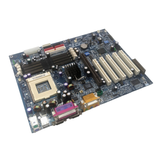
Page 13: 8Tx Motherboard Layout
8TX Motherboard 8TX Motherboard Layout PS/2 Socket 423 Processor AGP 1 AC97 JP25 PCI1 PCI2 JP23 JP22 JP24 PCI3 PCI4 PCI5 Intel 82850 JP16 ICH2 JP21 CN10 JP13 JP20 JP14 JP17 JP15 BAT1 JP12 JP10 JP11... -
Page 14: Installation Guide
Installation Guide Getting Started WARNING! Computer motherboards and expansion cards contain very delicate Integrated Circuit (IC) chips. To protect them against damage from static electricity, you should follow some precautions whenever you work on your computer. Unplug your computer when working on the inside. - Page 15 8TX Motherboard You may use the 4 screws which come with the mainboard to reinforce the support between P4 CPU heat-sink on the mainboard and chassis. Please note! In order to follow the installation steps below; your chassis must be WILLMETTE/850 board design compatible.
- Page 16 Installation Guide To set up your computer, you must complete the following steps: Step 1 - Set system jumpers Step 2- Install the Central Processing Unit (CPU) Step 3-Install memory modules Step 4-Install expansion cards Step 5-Connect ribbon cables, cabinet wires, and power supply Step 6-Set up BIOS software Step 7-Install supporting software tools Step 2...
- Page 17 8TX Motherboard CPU Speed Setup The system bus frequency can be switched at 100MHz - 133MHz by adjusting SW 1. (The frequency ratio depend on CPU). SW1 Select the System Speed at 100MHz - 133MHz. CPU CLK *100MHz 105MHz 110MHz 133MHz *We recommend you to setup your system speed to 100MHz.
- Page 18 3.Align CPU and insert it 5.Slip the bracket on to the CPU retention and press both end to clip it on the retention. 6.Make sure the CPU fan is plugged to the CPU fan connector, than install complete. (Please refer to the cooler’s installation manual for detailed installation steps) ATX 12V Power Supply -Additional 4 pin connector for 12V current -Backward compatibility maintained with load sharing capability...
-
Page 19: Memory Installation
8TX Motherboard Memory Installation The motherboard has 4 Rambus In-line Memory Module (RIMM) sockets. The BIOS will automatically detects memory type and size. To install the memory module, just push it vertically into the RIMM Slot .The RIMM module can only fit in one direction due to the two notches. Please note;... - Page 20 Introduce RIMM (Rambus In-line Memory Module) Direct Rambus Memory Controller Directly support a Dual Direct Rambus * Channel Supports 300&400 MHz Direct Rambus * Channel @ 100MHz host bus frequency. Maximum memory array size up to 256MB using 64Mb/72Mb, 512MB using 128Mb/144Mb, 1GB using 256Mb/288Mb DRAM technology Supports up to 32 Direct Rambus devices per channel Supports a maximum DRAM address decode space of 4GB...
-
Page 21: Page Index For Connectors / Panel And Jumper Definition
8TX Motherboard Page Index for Connectors/Panel and Jumper Definition Connectors ATX Power Aux. Power COM A / COM B / LPT Port CN6 (PS/2 Keyboard & PS/2 Mouse Connector) CN7 (USB Connector) CN10 (Front USB Connector) Floppy Port Game & Audio Port IDE 1/IDE 2 (Primary/ Secondary) Port J2 (CD Audio Line In) J3 (AUX_IN) - Page 22 JP16 (Case Open) JP17 (STR Selection) JP20 (Rear USB Device Wake up Selection) JP21 (Front USB Device Wake Up Selection) BAT 1(Battery) Installation Guide P.31 P.32 P.32 P.33 P.33...
-
Page 23: Connectors
8TX Motherboard Connectors ATX Power Please note: AC power cord should only be connected to your power supply unit after ATX power cable and other related devices are firmly connected to the mainboard. Aux. Power Please note: The 6-pin Aux. Power connector provides additional current to meet the board’s +3.3VDC and +5VDC requirments. -
Page 24: Com A / Com B / Lpt Port
COM A / COM B / LPT Port Please note: This mainboard supports 2 standard COM ports and 1 LPT port. Device like printer can be connected to LPT port ; mouse and modem etc can be connected to COM ports. CN6 : PS/2 Keyboard &... -
Page 25: Cn7 (Usb Connector)
8TX Motherboard CN7 : USB Connector Please note: Before you connect your device(s) into USB connector(s), please make sure your device(s) such as USB keyboard, mouse, scanner, zip, buzzer..etc. have a standard USB interface. Also make sure your OS (Win 95 w/ USB supperment, Win98, Windows 2000, Windows ME, Win NT w/ SP 6) supports USB controller. -
Page 26: Floppy Port
Floppy Port Game & Audio Port Please note: Line Out 1: Line Out or SPDIF (The SPDIF output is capable of providing digital audio to external speakers or compressed AC3 data to an external Dolby digital decoder). To enable SPDIF, simply insert SPDIF connector into Line Out1. -
Page 27: J2 (Cd Audio Line In)
8TX Motherboard IDE1(Primary) , IDE2 (Secondary) Port J2 : CD Audio Line In RED LINE IDE 2 IDE 1 Pin No. Definition CD-L CD-R... -
Page 28: J3 (Aux_In)
J3 : AUX IN J4 : TEL(The connector is for internal modem card with voice connector) Pin No. Definition AUX-L AUX-R Pin No. Definition Signal-In Signal-Out Connectors... -
Page 29: J8 (Ring Power On)
8TX Motherboard J8 : Ring Power On J11 : External SMBUS Device Connector Pin No. Definition Signal Pin No. Definition SMB CLK SMB DATA... -
Page 30: J12 (System Fan)
J12 : System FAN J13 : Power FAN Pin No. Definition Control +12V SENSE Pin No. Definition Control +12V SENSE Connectors... -
Page 31: J14 (Cpu Fan)
8TX Motherboard J14 : CPU FAN Please note , a proper installation of the CPU cooler is essential to prevent the CPU from running under abnormal condition or damaged by overheating. J16 : ATX +12V Power Connector Please note , This connector (ATX +12V) is only for heavy loading AGPPRO card. -
Page 32: J17 (Wake On Lan)
J17 : Wake on LAN JP12: STR LED Connector Please note: Do not remove memory modules while RIMM LED is on. It might cause short or other unexpected damages due to the 2.5V stand by voltage. Remove memory modules only when STR function is disabled by jumper and AC Power cord is disconnected. -
Page 33: Jp15 (Ir/Cir)
8TX Motherboard JP15 : IR/CIR Please note :Warning make sure that pin 1 on the IR device is align with pin one of the connector. To enable the IR/CIR function on the board, you are required to purchase an option IR/CIR module. For detail information please contact your authorized Giga-Byte distributor. -
Page 34: Panel And Jumper Definition
Panel And Jumper Definition J7 : For 2X11 Pins Jumper GN (Green Switch) GD (Green LED) HD (IDE Hard Disk Active LED) SPK (Speaker Connector) RE (Reset Switch) P+P P (Power LED) PW (Soft Power Connector) Please note , Please connect the power LED, PC speaker, reset switch and power switch etc of your chassis front panel to the front panel jumper according to the pin assignment above. -
Page 35: J9 (Internal Buzzer Connector)(Optional)
8TX Motherboard J9 : Internal Buzzer Connector(Optional) JP5 : Clear CMOS Function Please note , You may clear the CMOS data to its default values by this jumper Enable Disable (Default) Pin No. Definition 2-3close Internal Buzzer Disable 1-2close Internal Buzzer Enable (Default) Clear CMOS Normal... -
Page 36: Jp6 (Safe Mode/Recovery/Normal)
JP6 : Safe mode / Recovery / Normal Please note , Sometime the system can not start up due to the setting in the CMOS/BIOS, to restore the CMOS/BIOS setting back to its safe setting the jumper can be set to 2-3. Once your system can start up you can set the jumper back to its normal position 1-2. -
Page 37: Jp10 (Top Block Lock)
8TX Motherboard JP8 : PCI Sound Function Selection JP10 : Top Block Lock Please note , To upgrade BIOS on this M/B,JP10 must be set to 1&2. Enable Disable (Default) Pin No. Definition 1-2 close PCI Sound Enable(Default) 2-3 close PCI Sound Disable Lock Unlock... -
Page 38: Jp11 (Bios Write Protection)
JP11 : BIOS Write Protection Please note , To flash/upgrade BIOS on this MB JP 11 must be set to 2 & 3. We recommend JP 11 to be set to 1 & 2, whenever user does not need to flash/upgrade the BIOS. -
Page 39: Jp14 (Ps/2 Keyboard Power On)(Back)
8TX Motherboard JP14 : PS/2 Keyboard Power On Please note , Please note, PS/2 keyboard power on will enable user to power on his computer by pressing the designated key/keys on the PS/2 keyboard. To enable PS/2 keyboard power on, set jumper JP14 to 1-2, and then enable the PS/2 keyboard power on function to assign the key/keys of your choice inside the BIOS setup Menu. -
Page 40: Jp17 (Str Selection)
JP17 : STR Selection JP20 : Rear USB Device Wake up Selection (USB Connector Please note , To use “USB KB/MS Wakeup from S3” function, set BIOS setting “USB KB/MS Wake up from S3” to ENABLED and enable jumpers JP20&JP17. To prevent user confusion, it is recommended to enable, jumper JP21 (Front USB Device wake-up function). -
Page 41: Jp21 (Front Usb Device Wake Up Selection)
8TX Motherboard JP21 : Front USB Device Wake up Selection (USB Port CN10) Please note , To use “USB KB/MS Wakeup from S3” function, set BIOS setting “USB KB/MS Wake up from S3” to ENABLED and enable jumpers JP21&JP17. To prevent user confusion, it is recommended to enable, jumper JP20 (Rear USB Device wake-up function).. -
Page 42: Performance List
Hardware & Software configuration will result in different benchmark testing results.) Pentium DRAM (128x2) MB RDRAM (SAMSUNG MR16R0828AN1-CK8) CACHE SIZE 256 KB DISPLAY GIGABYTE GF-2000 DDR1.1 STORAGE Onboard IDE (IBM DTLA-307030 ) O.S. Windows 2000 SPK1 Display Driver Nvivia 0530 (NUCD 1.6C) DRIVER (1024 x 768 x 16bit colors x 75Hz.) -
Page 43: Block Diagram
8TX Motherboard Block Diagram AGP Pro 4X AGPCLK (66MHz) PCI Bus 33MHz Creative CT5880 Option AC97 CODEC 5 PCI PCI (33MHz) AGPCLK (66MHz) PCI (33MHz) 48MHz 14.318MHz 33MHz CPUCLK (100MHz) Pentium 4 System Bus 100MHz Intel 82850 300/400MHz HCLK (100/MHz) MCH (66MHz) 33MHz 14.318MHz... -
Page 44: Suspend To Ram Installation
Suspend To RAM Installation A.1 Introduce STR function: Suspend-to-RAM (STR) is a Windows 98 ACPI sleep mode function. When recovering from STR (S3) sleep mode, the system is able, in just a few seconds, to retrieve the last “state” of the system before it went to sleep and recover to that state. - Page 45 8TX Motherboard Step 2: (If you want to use STR Function, please set jumper JP17 Pin1-2 (Closed.) Step 3: Power on the computer and as soon as memory counting starts, press <Del>. You will enter BIOS Setup. Select the item “POWER MANAGEMENT SETUP”, then select “ACPI Sleep Type: S3 /STR”...
- Page 46 A.3 How to put your system into STR mode? There are two ways to accomplish this: Choose the “Stand by” item in the “Shut Down Windows” area. A. Press the “Start” button and then select “Shut Down” B. Choose the “Stand by” item and press “OK” Suspend to RAM Installation...
- Page 47 8TX Motherboard Define the system ”power on” button to initiate STR sleep mode: A. Double click “My Computer” and then “Control Panel” B. Double click the “ Power Management” item.
- Page 48 C. Select the “Advanced” tab and “Standby” mode in Power Buttons. D. Restart your computer to complete setup. Now when you want to enter STR sleep mode, just momentarily press the “Power on” button.. A.4 How to recover from the STR sleep mode? There are seven ways to “wake up”...
- Page 49 8TX Motherboard A.5 Notices : In order for STR to function properly, the hardware devices, such as AGP, Ethernet card, etc., and related drivers must be compliant with ACPI specification. ATX power supply must comply with the ATX 12V Power 1.1 specification (1.0 amps of 5V Stand-By current is minimum requirement, 2.0 amps was preferred).
-
Page 50: Dual Bios Introduction (Optional)
Dual BIOS Introduction (Optional) What is Dual BIOS Technology? Dual BIOS means that there are two system BIOS (ROM) on the motherboard, one is the Main BIOS and the other is Backup BIOS. Under normal circumstances, the system boots and works from the Main BIOS. If the Main BIOS is corrupted or damaged, the Backup BIOS can take over when the system is powers on. - Page 51 8TX Motherboard b. AMI Dual BIOS Flash ROM Programming Utility AMI Dual BIOS Flash ROM Programming Utility Boot From……………………….. Main BIOS Main ROM Type………………… Intel N82802AB Backup ROM Type……………… Intel N82802AB Wide Range Protection Auto Recovery Halt On Error Copy Main ROM Data to Backup PgDn/PgUp:Modify(Enter:Run) c.
- Page 52 Boot From : Main BIOS (Default), Backup BIOS Status 1: The user can set to boot from main BIOS or Backup BIOS. Auto Recovery : Enabled(Default), Disabled When one of the Main BIOS or Backup BIOS occurs checksum failure, the working BIOS will automatically recover the BIOS of checksum failure.
- Page 53 DualBIOS Technology FAQ GIGABYTE Technology is pleased to introduce DualBIOS technology, a hot spare for your system BIOS. This newest “Value-added” feature, in a long series of innovations from GIGABYTE, is available on GA-8TX motherboard. Future GIGABYTE motherboards will also incorporate this innovation.
- Page 54 I. Q: What is DualBIOS technology? Answer: DualBIOS technology is a patented technology from Giga-Byte Technology. The concept of this technology is based on the redundancy and fault tolerance theory. DualBIOS simply means there are two system BIOSes (ROM) integrated onto the motherboard. One is a main BIOS, and the other is a backup BIOS.
- Page 55 8TX Motherboard III. Q: How does DualBIOS Answer: 1. DualBIOS technology provides a wide range of protection during the boot up procedure. It protects your BIOS during system POST, ESCD update, and even all the way to PNP detection/assignment. 2. DualBIOS provides automatic recovery for the BIOS.
- Page 56 2. During or after a BIOS upgrade, if DualBIOS backup BIOS will take over the boot-up process automatically. Moreover, it will verify the main and backup BIOS checksums when booting-up. DualBIOS checksum of the main and backup BIOS while the system is powered on to guarantee your BIOS operates properly.
-
Page 57: Four Speaker & Spdif Introduction (Optional)
8TX Motherboard Four Speaker & SPDIF Introduction (Optional) Four Speaker Introduction What is Four Speaker? The Creative CT5880 audio chip can support up to 4 speaker output. If you select “Four speaker out”, Line In will be reconfigured as another line out to support a second pair of speakers. - Page 58 Four Speaker & SPDIF Introduction c. Select “Four speaker” item. Microsoft Windows Me setup procedure: a. Go to “Control Panel” Double click “Sounds and Multimedia”.
- Page 59 8TX Motherboard b. Select “Audio” Page, and click “Advanced” button. c. Select “Quadraphonic Speakers” and click ok. Four Speaker Application The four speaker function will only be supported in application softwares that use Microsoft DirectX and Creative EAX, for example, the game titles, software DVD player and MP3 player. Click ”Advanced”.
-
Page 60: Spdif Introduction
SPDIF Introduction What is SPDIF? The SPDIF output is capable of providing digital audio to external speakers or compressed AC3 data to an external Dolby digital decoder. How to use SPDIF? a. Click your mouse right button in “My Computer” and select the “Properties” item. b. - Page 61 8TX Motherboard c. Click “Sound, video and game controllers” item and select the “Creative Sound Blaster PCI128” item. d. Click “Settings” item and select the “Output Mode” item.
- Page 62 e. Click “Digital” item, Line Out will be reconfigure to SPDIF Out. f. Recommend you to select “Autosense”, It will automatically detect the type (mono or stereo) of the audio connector that you plug into Line Out audio jack, then configure Line Out to either SPDIF or Speaker accordingly.
-
Page 63: Bios Introduction (Optional)
BIOS, just choose “Save Current BIOS” to save it first. You make a wise choice to use Gigabyte, and @BIOS update your BIOS smartly. You are now worry free from updating wrong BIOS, and capable to maintain and manage your BIOS easily. -
Page 64: Easytuneiii Introduction (Optional)
Click “Advanced Mode” to enjoy “sport drive” class overclocking. In “Advanced Mode”, one can change the system bus speed in small increments to get ultimate system performance. And no matter which mainboard is used, if it’s a Gigabyte’s product*, EasyTuneIII helps to perform the best of system. - Page 65 8TX Motherboard For further technical information, please link to: http://www.gigabyte.com.tw Note: If your IUCD version is 1.6 or below, please visit our website and download the latest EasyTune III TM version.
-
Page 66: Page Index For Bios Setup
Page Index for BIOS Setup The Main Menu Standard CMOS Setup BIOS Features Setup Chipset Features Setup Power Management Setup PNP/ PCI Configuration Load BIOS Defaults Load Setup Defaults Integrated Peripherals Hardware Monitor Setup Supervisor / User Password IDE HDD Auto Detection Save &... -
Page 67: Entering Setup
8TX Motherboard BIOS Setup BIOS Setup is an overview of the BIOS Setup Interface. The interface allows users to modify the basic system configuration, which is stored in battery-backed CMOS RAM so that it retains the Setup information can be retained when the power is turned off. ENTERING SETUP Power ON the computer and press <Del>... -
Page 68: Getting Help
GETTING HELP Main Menu The on-line description of the highlighted setup function is displayed at the bottom of the screen. Status Page Setup Menu / Option Page Setup Menu Press F1 to pop up a small help window that describes the appropriate keys to use and the possible selections for the highlighted item. - Page 69 8TX Motherboard Standard CMOS Setup This setup page includes all the adjustable items in standard compatible BIOS. BIOS Features Setup This setup page includes all the adjustable items of Award special enhanced features. Chipset Features Setup This setup page includes all the adjustable items of chipset special features. Power Management Setup This setup page includes all the adjustable items of Green function features.
-
Page 70: Standard Cmos Setup
Standard CMOS Setup The items in Standard CMOS Setup Menu (Figure 2) are divided into 10 categories. Each category includes none, one or more than one setup items. Use the arrows to highlight the item and then use the <PgUp> or <PgDn> keys to select the value in each item. AMIBIOS SETUP –... - Page 71 8TX Motherboard Primary Master / Slave , Secondary Master / Slave The category identifies the type of hard disk from drive C to F that has been installed in the computer. There are two settings: Auto, and Manual. Manual: HDD type is user-definable; Auto will automatically detect HDD type.
-
Page 72: Extended Memory
Boot Sector Virus Protection If it is set to enable, the category will flash on the screen when there is any attempt to write to the boot sector or partition table of the hard disk drive. The system will halt and the following error message will appear in the mean time. -
Page 73: Bios Features Setup
8TX Motherboard BIOS Features Setup AMIBIOS SETUP – BIOS FEATURES SETUP ( C ) 1999 American Megatrends, Inc. All Rights Reserved 1st Boot Device 2nd Boot Device 3rd Boot Device Floppy Drive Seek BootUp Num-Lock Password Check S.M.A.R.T. for Hard Disks 1st / 2nd / 3rd Boot Device Floppy Set your boot device priority to Floppy. -
Page 74: Password Check
Boot Up Num-Lock Keypad is number keys. (Default Value) Keypad is arrow keys. Password Check Please refer to the detail on P.81 Setup The user must enter correct password in order to access BIOS setup utility. (Default Value) Always The user must enter correct password in order to access the system and/or BIOS Setup. -
Page 75: Chipset Features Setup
8TX Motherboard Chipset Features Setup We would not suggest you change the chipset default setting unless you really need it. AMIBIOS SETUP – CHIPSET FEATURES SETUP ( C ) 1999 American Megatrends, Inc. All Rights Reserved CPU Frequency Ratio RDRAM Bus Frequency Over RIMM Voltage Memory ECC Mode Memory Hole... -
Page 76: Delayed Transaction
Memory Hole Normal Setting . (Default Value) Disabled 15MB~16MB Set Address=15~16MB relocate to ISA BUS. Graphics Aperture Size 4 MB Display Graphics Aperture Size is 4MB. 8 MB Display Graphics Aperture Size is 8MB. 16 MB Display Graphics Aperture Size is 16MB. 32 MB Display Graphics Aperture Size is 32MB. -
Page 77: Power Management Setup
8TX Motherboard Power Management Setup AMIBIOS SETUP – POWER MANAGEMENT SETUP ( C ) 1999 American Megatrends, Inc. All Rights Reserved ACPI Sleep Type USB Dev Wakeup From S3 Suspend Time Out (Minute) Throttle Slow Clock Ratio Soft-Off by Power Button System After AC Back ModemRingOn/WakeOnLan PME Event Wake Up... - Page 78 Soft-off by Power Button Instant off The user press the power button once, he can turn off the system. (Default Value) Suspend The user press the power button once, then he can enter suspend mode. System after AC Back When AC-power back to the system, the system will be in “Off” state. (Default Value) When AC-power back to the system, the system will be in ”On”...
- Page 79 8TX Motherboard FDC/LPT/COM Ports Access Monitor FDC/LPT/COM Ports Access. (Default Value) Monitor Ignore Ignore FDC/LPT/COM Ports Access. Pri. Master IDE Access Monitor Primary Master IDE Access. (Default Value) Monitor Ignore Ignore Primary Master IDE Access. Pri. slave IDE Access Monitor Monitor Primary slave IDE Access.
-
Page 80: Pnp/Pci Configuration
PNP/PCI Configuration AMIBIOS SETUP – PNP / PCI CONFIGURATION ( C ) 1999 American Megatrends, Inc. All Rights Reserved Reset Configuration Data VGA Boot From IRQ-3 IRQ-4 IRQ-5 IRQ-7 IRQ-9 IRQ-10 IRQ-11 IRQ-14 IRQ-15 Reset Configuration Data Advising BIOS clear PnP configuration data for usable value. Disabled Disabled this function. -
Page 81: Load Bios Defaults
8TX Motherboard Load BIOS Defaults AMIBIOS SIMPLE SETUP UTILITY-VERSION 1.24a ( C ) 1999 American Megatrends, Inc. All Rights Reserved STANDARD CMOS SETUP BIOS FEATURES SETUP CHIPSET FEATURES SETUP POWER MANAGEMENT SETUP Load BIOS Defaults (Y/N)?N PNP/PCI CONFIGURATION LOAD BIOS DEFAULTS LOAD SETUP DEFAULTS ESC : Quit : Select Item (Shift) F2 : Change Color F5 : Old Values... -
Page 82: Load Setup Defaults
Load Setup Defaults AMIBIOS SIMPLE SETUP UTILITY-VERSION 1.24a ( C ) 1999 American Megatrends, Inc. All Rights Reserved STANDARD CMOS SETUP BIOS FEATURES SETUP CHIPSET FEATURES SETUP POWER MANAGEMENT SETUP Load Setup Defaults (Y/N)?N PNP/PCI CONFIGURATION LOAD BIOS DEFAULTS LOAD SETUP DEFAULTS ESC : Quit : Select Item (Shift) F2 : Change Color F5 : Old Values : Load BIOS Defaults... -
Page 83: Integrated Peripherals
8TX Motherboard Integrated Peripherals AMIBIOS SETUP – INTEGRATED PERIPHERALS ( C ) 1999 American Megatrends, Inc. All Rights Reserved OnBoard IDE OnBoard FDC OnBoard Serial Port A OnBoard Serial Port B Serial Port B Mode IR Duplex Mode OnBoard CIR Port CIR IRQ Select OnBoard Parallel Port Parallel Port Mode... - Page 84 OnBoard Serial Port B BIOS will automatically setup the port B address. (Default Value) Auto 3F8/COM1 Enable OnBoard Serial port B and address is 3F8. 2F8/COM2 Enable OnBoard Serial port B and address is 2F8. 3E8/COM3 Enable OnBoard Serial port B and address is 3E8. 2E8/COM4 Enable OnBoard Serial port B and address is 2E8.
- Page 85 8TX Motherboard Parallel Port Mode Using Parallel port as Enhanced Parallel Port. Using Parallel port as Extended Capabilities Port. (Default Value) Normal Normal Operation. EPP Version Compliant with EPP 1.9 version. Compliant with EPP 1.7 version. (Default Value) Parallel Port IRQ Set Parallel Port IRQ to 7.
- Page 86 Mouse PowerOn Function Disable this function. (Default Value) Disabled Right –button Click right-button to power on the system. Left-button Click Left-button to power on the system. Keyboard Power On Function Disable this function. (Default Value) Disabled Specific key Set password key to power on by keyboard. Power Key Set “Power key”...
-
Page 87: Hardware Monitor Setup
8TX Motherboard Hardware Monitor Setup AMIBIOS SETUP – HARDWARE MONITOR SETUP ( C ) 1999 American Megatrends, Inc. All Rights Reserved CPU Temp. Alarm CPU Fan Fail Alarm Power Fan Fail Alarm System Fan Fail Alarm Reset Case Open Status Case Status Current CPU Temp. - Page 88 BIOS Setup Current CPU Tempe. Detect CPU Temp. automatically. Current System Tempe. Detect System Temp. automatically. Current CPU FAN / System FAN / Power FAN Speed (RPM) Detect Fan speed status automatically. Current CPU VID / Vcore / Vcc18 / Vio / 12V / +5V / Battery / +5VSB Detect system’s voltage status automatically.
-
Page 89: Supervisor / User Password
8TX Motherboard Supervisor / User Password When you select this function, the following message will appear at the center of the screen to assist you in creating a password. AMIBIOS SIMPLE SETUP UTILITY-VERSION 1.24a ( C ) 1999 American Megatrends, Inc. All Rights Reserved STANDARD CMOS SETUP BIOS FEATURES SETUP CHIPSET FEATURES SETUP... -
Page 90: Ide Hdd Auto Detection
IDE HDD Auto Detection AMIBIOS SETUP – STANDARD CMOS SETUP ( C ) 1999 American Megatrends, Inc. All Rights Reserved Date (mm/dd/yyyy) : Tue Jan 18, 2000 Time (hh/mm/ss) : 10:36:24 TYPE SIZE CYLS HEAD PRECOMP LANDZ SECTOR MODE Pri Master : Auto Pri Slave : Auto... -
Page 91: Save & Exit Setup
8TX Motherboard Save & Exit Setup AMIBIOS SIMPLE SETUP UTILITY-VERSION 1.24a ( C ) 1999 American Megatrends, Inc. All Rights Reserved STANDARD CMOS SETUP BIOS FEATURES SETUP CHIPSET FEATURES SETUP POWER MANAGEMENT SETUP SAVE to CMOS and EXIT(Y/N)? Y PNP/PCI CONFIGURATION LOAD BIOS DEFAULTS LOAD SETUP DEFAULTS ESC : Quit... -
Page 92: Exit Without Saving
Exit Without Saving AMIBIOS SIMPLE SETUP UTILITY-VERSION 1.24a ( C ) 1999 American Megatrends, Inc. All Rights Reserved STANDARD CMOS SETUP BIOS FEATURES SETUP CHIPSET FEATURES SETUP POWER MANAGEMENT SETUP Quit without saving (Y/N)? N PNP/PCI CONFIGURATION LOAD BIOS DEFAULTS LOAD SETUP DEFAULTS ESC : Quit : Select Item (Shift) F2 : Change Color F5 : Old Values... - Page 93 8TX Motherboard Technical Support /RMA Sheet Customer/Country: Company: Contact Person: Model name/Lot Number: BIOS version: Hardware Mfs. Model name Size: Configuration Memory Brand Video Card Audio Card CD-ROM / DVD-ROM Modem Network AMR / CMR Keyboard Mouse Power supply Other Device Problem Description: Phone No.: E-mail Add.
-
Page 94: Appendix
Appendix Appendix A: Intel 850 Chipset Driver Installation A. Windows 9x INF Update Utility Insert the support CD that came with your motherboard into your CD-ROM drive or double-click the CD drive icon in My Computer to bring up the setup screen. 1.Click “Windows 9x/2k INF Update Utility”... - Page 95 8TX Motherboard B. Intel ICH IDE ATA100 Driver Installation Insert the support CD that came with your motherboard into your CD-ROM drive or double-click the CD drive icon in My Computer to bring up the setup screen. 1.Click “Intel Utility ATA Storage Driver”...
- Page 96 Appendix 6.Click “Finish” to restart computer.
- Page 97 8TX Motherboard Appendix B: Creative Sound Driver Installation Insert the support CD that came with your motherboard into your CD-ROM drive or double-click the CD drive icon in My Computer to bring up the setup screen. 1.Click here. 3.Click”OK” item. 5.Click”Next”...
- Page 98 7.We recommend you to click this item. 8.Click”Next” item. 9.Click “Finish” to restart. (10) Appendix...
- Page 99 8TX Motherboard Appendix B: BIOS Flash Procedure BIOS update procedure: If your OS is Win9X, we recommend that you used Gigabyte @BIOS Program to flash BIOS. Click “Tool” . Click “@BIOS Writer v1.05a” Click “ ” . Methods and steps : I.
- Page 100 In method I, if the BIOS file you need cannot be found in @BIOS server, please go onto Gigabyte's web site for downloading and updating it according to method II. d. Please note that any intercorruption during updating will cause system unbooted...
- Page 101 Format a bootable system floppy diskette by the command “ format a:/s ” in command mode. Visit the Gigabyte website at http:// www.gigabyte.com.tw, Select the BIOS file you need and download it to your bootable floppy diskette. Insert the bootable diskette containing the BIOS file into the floppy diskette driver.
- Page 102 Appendix D: Acronyms Acronyms Meaning ACPI Advanced Configuration and Power Interface Advanced Power Management Accelerated Graphics Port Audio Modem Riser Advanced Communications Riser BIOS Basic Input / Output System Central Processing Unit CMOS Complementary Metal Oxide Semiconductor CRIMM Continuity RIMM Communication and Networking Riser Direct Memory Access Desktop Management Interface...
- Page 103 8TX Motherboard Acronyms Meaning Original Equipment Manufacturer PCI A.G.P. Controller POST Power-On Self Test Peripheral Component Interconnect RIMM Rambus in-line Memory Module Special Circumstance Instructions SECC Single Edge Contact Cartridge SRAM Static Random Access Memory Symmetric Multi-Processing System Management Interrupt Universal Serial Bus Voltage ID...