
Related Manuals for Toshiba 14AR22


Summary of Contents for Toshiba 14AR22
- Page 1 TOSHIBA FILE NO.050-200216 SERVICE MANUAL COLOR TELEVISION 14AR22 V OL AUT O V OL T AGE DOCUMENT CREATED IN JAPAN, Aug., 2002...
-
Page 2: Table Of Contents
COLOR TELEVISION Chassis No. MSA 14AR22 V OL AUT O V OL T AGE MODEL In the interests of user-safety (Required by safety regulations in some countries) the set should be restored to its original condition and only parts identical to those specified should be used. -
Page 3: Important Service Safety Precaution
14AR22 IMPORTANT SERVICE SAFETY PRECAUTION Ë Service work should be performed only by qualified service technicians who are thoroughly familiar with all safety checks and the servicing guidelines which follow: WARNING X-RADIATION AND HIGH VOLTAGE LIMITS 1. For continued safety, no modification of any circuit 1. - Page 4 14AR22 IMPORTANT SERVICE SAFETY PRECAUTION (Continued) • Connect the resistor connection to all exposed metal BEFORE RETURNING THE RECEIVER parts having a return to the chassis (antenna, metal (Fire & Shock Hazard) cabinet, screw heads, knobs and control shafts, escutcheon and etc.) and measure the AC voltage Before returning the receiver to the user, perform drop across the resistor.
-
Page 5: Location Of User's Control
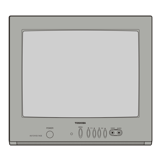
14AR22 LOCATION OF USER'S CONTROL Front Panel VIDEO/AUDIO TERMINALS (VIDEO/AUDIO terminals are also provided on the rear.) AUT O V OL T AGE POWER CHANNEL UP/DOWN Press ( ) Selects next higher channel. ( ) Selects next lower channel. Press again Off. -
Page 6: Installation And Service Instructions
14AR22 INSTALLATION AND SERVICE INSTRUCTIONS Note: (1) When performing any adjustments to resistor controls and transformers use non-metallic screwdrivers or TV alignment tools. (2) Before performing adjustments, the TV set must be on at least 15 minutes. HIGH VOLTAGE CHECK CIRCUIT PROTECTION The receiver is protected by a 3.15A fuse (F701),... - Page 7 14AR22 For adjustments of this model, the bus data is converted to various analog signals by the D/A converter circuit. Note: There are still a few analog adjustments in this series such as focus and master screen voltage. Follow the steps below whenever the service adjustment is required. See "Table-B" to determine, if serv- ice adjustments are required.
- Page 8 14AR22 SERVICE MODE (1) In the Service Mode, Key is used to select the mode in the following oreder. AGC & WHITE POINT GEOMETRIC ADJ. ADJ. MODE MODE MODE OFFSET ADJ. MODE FEATURE OPTION OPTION ADJ. MODE MODE MODE AGC &...
- Page 9 14AR22 OFFSET ADJ. ADJ. MODE MODE ↓ ↓ Y-D TIME (TV) [ YD ] (DL-TV) ATTENUATE INPUT SIGNAL LEVEL (ATT) ↓ ↓ Y-D TIME (AV) [ YD ] (DL-AV) VCO FREE RUNNING FREQUENCY ADJ. (VCO) ↓ ↓ INITIAL/DEFAULT LANGUAGE (INIT) STEREO, SAP, DBX FILTER ADJ.
- Page 10 14AR22 SERVICE MODE DATA SERVICE REMARK ADJUST ITEM POSITION RANGE INITIAL VALUE FIX/ADJ AGC TAKE OVER POINT 0~63 V-LIN VERTICAL SLOPE 0~63 V-AMP VERTICAL AMP 0~63 V-CENT VERTICAL SHIFT 0~63 V-ZOOM VERTICAL ZOOM 0~63 H-CENT HORIZONTAL SHIFT 0~63 H-SIZE EAST-WEST WIDTH...
- Page 11 14AR22 DATA SERVICE REMARK ADJUST ITEM POSITION RANGE INITIAL VALUE FIX/ADJ FMWS FM WINDOW SELECTION 0(disable) or1(enable) SOUND MUTE BIT 0 (SM0) 0(disable) or1(enable) SOUND MUTE BIT 1 0(disable) or1(enable) AGC0 IF AGC SPEED BIT 0 0(disable) or1(enable) AGC1 IF AGC SPEED BIT 1...
- Page 12 14AR22 Ë SERVICE ADJUSTMENT RF AGC Adjustment 1. Receive a good local channel. 2. Enter the service mode signal category and select the service adjustment "AGC". 3. Set the data value to point where no noise or beat appears. 4. Select another channel to confirm that no noise or beat appears.
- Page 13 14AR22 CRT CUT-OFF, BACKGROUND AND SUB-CONTRAST ADJUSTMENT No. Adjusting point Adjusting procedure/conditions Waveform and others CRT CUTOFF 1. Switch TV to VIDEO mode,BLUE BACK OFF, with ADJUSTMENT NO VIDEO signal. 3.0Vdc C BUS 2. Press R/C to set Picture Normal condition.
-
Page 14: Chassis Layout
14AR22 CHASSIS LAYOUT... -
Page 15: Block Diagram
14AR22 BLOCK DIAGRAM... -
Page 16: Description Of Schematic Diagrams
14AR22 DESCRIPTION OF SCHEMATIC DIAGRAM WAVEFORM MEASUREMENT CONDITIONS: NOTES: 1. Photographs taken on a standard gated color bar 1. The unit of resistance "ohm" is omitted. (K=k Ω =1000 Ω , M=M Ω ) signal, the tint setting adjusted for proper color. The wave shapes at the red, green and blue cathodes of 2. - Page 17 14AR22 SCHEMATIC DIAGRAM: MAIN UNIT...
- Page 18 SCHEMATIC DIAGRAM: MAIN UNIT...
- Page 19 14LK22...
- Page 20 14AR22 SCHEMATIC DIAGRAM: CRT Units...
-
Page 21: Printed Wiring Board Assemblies
14AR22 PRINTED WIRING BOARD ASSEMBLIES PWB-B: CRT Unit (Wiring Side) PWB-B: CRT Unit (Chip Parts Side) - Page 22 14AR22 PWB-A: MAIN Unit (Wiring Side)
- Page 23 14AR22 PWB-A: MAIN Unit (Chip Parts Side)
- Page 24 14AR22 Toshiba Part No. Part No. Ref.No. Description PARTS LIST PWB-A: DUNTKA541WEA6 PARTS REPLACEMENT MAIN UNIT Replacement parts which have these special safety characteristics identified in this manual; electrical components having such features TUNER å are identified by and shaded areas in the Replacement Parts Lists NOTE : THE PARTS HERE SHOWN ARE SUPPLIED AS AN and Schematic Diagrams.
- Page 25 14AR22 Toshiba Part No. Part No. Ref.No. Description Toshiba Part No. Part No. Ref.No. Description PWB-A: DUNTKA541WEA6 AD100481 VCKYCY1HB102K C531 1000p 50V Ceramic AD100481 VCKYCY1HB102K C532 1000p 50V Ceramic MAIN UNIT (Continued) AD100499 VCQYTA1HM104J C533 Mylar AD100503 VCQYTA1HM563J+ C601 0.056 50V...
- Page 26 14AR22 Toshiba Part No. Part No. Ref.No. Description Toshiba Part No. Part No. Ref.No. Description AD100582 VRS-CY1JF750J R432 1/16W M-Ox. PWB-A: DUNTKA541WEA6 AD100644 VRD-RA2BE272J R501 2.7k 1/8W Carbon AD100535 VRD-RM2HD102J R502 1.0k 1/2W Carbon MAIN UNIT (Continued) AD100648 VRN-RL3DB2R7J R503...
- Page 27 14AR22 Toshiba Part No. Part No. Ref.No. Description Toshiba Part No. Part No. Ref.No. Description PWB-A: DUNTKA541WEA6 PWB-B: DUNTKA542WEA2 MAIN UNIT (Continued) CRT UNIT AD100577 VRS-CY1JF562J R1009 5.6k 1/16W M-Ox. TRANSISTORS AD100570 VRS-CY1JF332J R1011 3.3k 1/16W M-Ox. AD100425 RH-TX0110BMZZ+ Q870...
- Page 28 14AR22 Toshiba Part No. Part No. Ref.No. Description Toshiba Part No. Part No. Ref.No. Description MISCELLANEOUS PARTS CABINET PARTS AD100359 QACCZ3008PEZZ ACC701 AC Cord AD100667 CCABAA105WEH0 Front Cabinet Ass'y AD100656 VSP0080PBQ9YA SP301 Spea ker, 32 ohm Not Available Front Cabinet...
-
Page 29: Packing Of The Set
14AR22 Ref. No. Part No. Description Code Ref. No. Part No. Description Code PACKING OF THE SET # Polyethylene Bag Operation Manual Infrared R/C Unit # Batteries # Wrapping Paper # Buffer Material FRONT # Packing Case Use tape to fix top side of pack case. - Page 30 TOSHIBA CORPORATION 1-1, SHIBAURA 1-CHOME, MINATO-KU, TOKYO 105-8001, JAPAN...