Gigabyte MZ01-CE0 Quick Reference Manual
Hide thumbs
Also See for MZ01-CE0:
- Quick reference manual (2 pages) ,
- User manual (120 pages) ,
- Quick reference manual (2 pages)
Advertisement
Quick Links
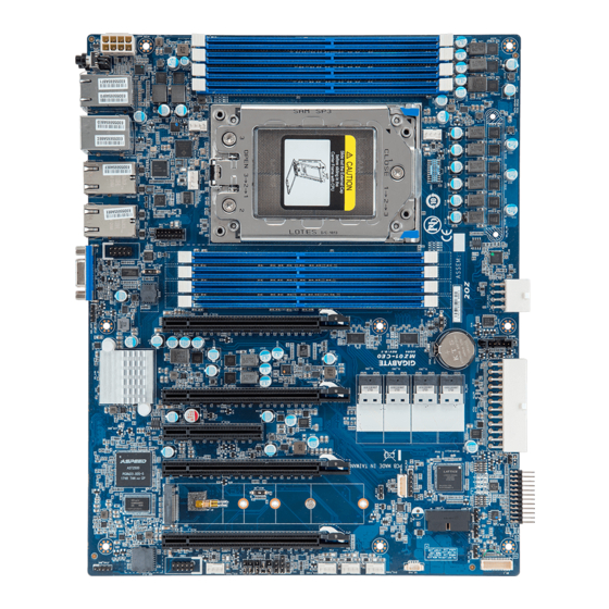
Motherboard Components
36
37
1
2 3 4 5 6
31
29
30
32 33 34
35
28
27
26
15
25
16
24
17
23
18
14
22
21
20
19
13
12
11
No.
Code
Description
1
VGA
VGA Port
2
10GLAN1
10G LAN Port #1 (MZ01-CE0 Only)
3
LPC_TPM
TPM Module Connector
4
10GLAN2
10G LAN Port #2 (MZ01-CE0 Only)
5
SYS_FAN2
System Fan Connector #2
ATX Power/ 电源
P12V_AUX1 P12V_AUX2
12
13
24
No.
Pin Define
No.
Pin Define
1
3.3V
13
3.3V
2
3.3V
14
-12V
3
GND
15
GND
4
+5V
16
PS_ON
5
GND
17
GND
6
+5V
18
GND
7
GND
19
GND
8
Power Good
20
-5V
9
5VSB
21
+5V
22
+5V
10
+12V
11
+12V
23
+5V
12
3.3V
24
GND
Front Panel Header / 前面板
1
23
2
24
No.
Pin Define
No.
Pin Define
1
Power LED+
2
5V Standby
3
No Pin
4
ID LED+
5
Power LED-
6
ID LED-
7
HDD LED+
8
System Status LED+
9
HDD LED-
10
System Status LED-
11
Power Button
12
LAN1 Active LED+
13
GND
14
LAN1 Link LED-
15
Reset Button
16
SMBus Data
17
GND
18
SMBus Clock
19
No Connect
20
Case Open
21
GND
22
LAN2 Active LED+
23
NMI Switch
24
LAN2 Link LED-
Serial Port Cable Connector
USB 3.0 Header
1
2
11
20
10
1
No.
Pin Define
No.
Pin Define
1
Power (5V)
11
IntA_P2_D+
2
IntA_P1_SSRX-
12
IntA_P2_D-
3
IntA_P1_SSRX+
13
GND
9
10
4
GND
14
IntA_P2_SSTX+
5
IntA_P1_SSTX-
15
IntA_P2_SSTX-
Case Open Intrusion Header
6
IntA_P1_SSTX+
16
GND
7
GND
17
IntA_P2_SSRX+
8
IntA_P1_D-
18
IntA_P2_SSRX-
Open: Normal operation.
9
IntA_P1_D+
19
Power (5V)
10
NC
20
No Pin
Closed: Active chassis intrusion alert.
TPM Connector/
可信平台模块
BMC Firmware Readiness LED
State
No.
Pin Define
No.
Pin Define
1 2
On
1
Clock
8
No Connect
Blink
2
P_3V3_AUX
9
LPC_LAD2
Off
3
LPC_RST
10
No Pin
4
P3V3
11
LPC_LAD3
TPM Module
5
LPC_LAD0
12
GND
6
IRQ_SERIAL
13
LPC_FRAME_N
13 14
7
LPC_LAD1
14
GND
PN.12QM1-MZ01CE-00H
MZ01-CE0/MZ01-CE1 Quick Reference Guide/ 快速测试参考指南
No.
Code
Description
6
USB3_MLAN
Server Management LAN Port (top)
7
8
9 10
USB 3.0 Ports (Bottom)
7
SYS_FAN1
System Fan Connector #1
8
LAN1_2
GbE LAN Port #1 (top)/Port #2 (bottom)
9
SW_PWR
Power Button(top)/ID Button (Bottom)
10
P12V_AUX1
2 x 4 Pin Power Connector (for CPU)
11
CPU0_FAN
CPU Fan Connector
12
P12V_AUX2
2 x 4 Pin Power Connector (for Memory)
13
PMBUS
PMBus Connector
14
BAT1
System Battery
15
SL_CN1
SlimLine 4i Connector #1 (SATA Signal)
16
SL_CN2
SlimLine 4i Connector #2 (SATA Signal)
17
SL_CN3
SlimLine 4i Connector #3 (SATA Signal)
18
SL_CN4
SlimLine 4i Connector #4 (SATA Signal)
19
ATX1
2 x 13 Pin System Power Connector
CPU
20
CASE_OPEN
Case Open Intrusion Header
21
FP_1
Front Panel Header
22
BP_1
HDD Back Plane Board Connector
23
F_USB3
Front Panel USB 3.0 Connector
24
IPMB
IPMB Connector
25
SYS_FAN5
System Fan Connector #5
26
SYS_FAN4
System Fan Connector #4
27
SYS_FAN3
System Fan Connector #3
28
SYS_FAN6
System Fan Connector #6
29
COM2
Serial Port Cable Connector #2
30
PCIE_1
PCIe x 16 Slot #1
31
M2_0
M.2 Connector
(PCIe Gen3 x4, NGFF-2280, M-Key)
32
PCIE_3
PCIe x 16 Slot #3
33
PCIE_4
PCIe x 8 Slot #4
34
PCIE_5
PCIe x 16 Slot #5
35
PCIE_7
PCIe x 16 Slot #7
36
LED_BMC
BMC Firmware Readiness LED
37
COM1
Serial Port Cable Connector #1
CPU/System FAN/ 风扇
5 1
1
No.
Pin Define
1
GND
4
8
2
+12V
1
5
3
Sense
4
8 4
4
Speed Control
No.
Pin Define
1
GND
PMBUS
2
GND
3
GND
No.
Pin Define
4
GND
5
1
PMBus Clock
5
+12V
2
PMBus Data
6
+12V
3
PMBus Alert
7
+12V
4
GND
8
+12V
1
5
3.3V Sense
HDD Back Plane Board Header/ 硬盤背板排針
No.
Pin Define
No.
Pin Define
1
Reserved
16
BP_RST_N
2
BP_SGDIN
17
SMB_U2_TMP_SCL
3
GND
18
GND
1 2
4
BP_SGDOUT
19
SMB_U2_TMP_SDA
5
BP_SGLD
20
I2C_DEV_RST
6
GND
21
RSVD
7
BP_SGCLK
22
GND
8
PLD_Program_EN
23
Reserved
9
GLED_AMB_N
24
GND
10
GLED_GRN_N
25
Reserved
29 30
11
FAN_IRQ_N
26
GND
12
Reserved
27
Reserved
13
BP_SCL
28
GND
14
GND
29
P_3V3_AUX
15
BP_SDA
30
P_3V3_AUX
Jumper Settings/ 跳线设置
No.
Pin Define
No.
Pin Define
1
NDCD-
6
NDSR-
2
NSIN
7
NRTS-
3
NSOUT
8
NCTS-
4
NDTR-
9
NRI-
5
GND
10
No Pin
Default
Clear CMOS
CLR_CMOS
Default
Password
Clear
BIOS_PWD
PMBus
Default
Address
Select
PSMB_SEL
Description
BMC firmware is initial
Default
BIOS
BMC firmware is ready
Recovery
AC loss
BIOS_RCVR
Installing CPU/ 安装 CPU
1
2
3
4
1
2
9
3
8
NOTE!
When installing the heatsink to CPU,
use T20-Lobe driver to tighten 4 captive nuts
in sequence as 1-4.
The screw tightening torque:
16.1 ± 1.2 kgf-cm (14.0± 1.0 lbf-in)
Rear I/O Connector/ 后面板接口
3
5
7
1
6
2
4
No.
Description
1
Power Button
2
ID Button
3
GbE LAN port #3
4
GbE LAN port #4
5
Server Management LAN Port
6
USB 3.0 Port x 2
LAN LED
10/100/1000 LAN LED:
Speed LED Link/Activity
LED
State
Yellow On
Green On
Off
10G LAN LED:
Speed LED Link/Activity
LED
State
Yellow On
Green On
Off
SPI/ESPI Select Switch
ON
OFF
ESPI Mode
SPI Mode
Enable
1 2 3
Enable
1 2 3
Enable
1 2 3
Enable
1 2
3
Memory Population Configuration/ 安装内存
External cap
3
1
2
4
5
6
RDIMM Maximum Frequency Supported Table
Slots
Populated
7
2
1
3
1
2
LRDIMM Maximum Frequency Supported Table
8
9
Slots
Populated
1
No.
Description
7
10G LAN port #2 (MZ01-CE0 Only)
8
10G LAN port #1 (MZ01-CE0 Only)
9
VGA Port
2
Description
1Gbps data rate
3DS RDIMM Maximum Frequency Supported Table
100Mbps data rate
10Mbps data rate
Slots
Populated
Description
1
10Gbps data rate
1Gbps data rate
100 Mbps data rate
2
NOTE!
1R: 1 package rank of SDP DRAMs
2R: 2 package rank of SDP DRAMs
2DR: 2 package rank of DDP DRAMs
4DR: 2 package rank of DDP DRAMs
1S2R/1S4R/1S8R: 1 package rank of 2/4/8 high 3DS DRAMs
2S2R/2S4R/2S8R: 2 package rank of 2/4/8 high 3DS DRAMs
DIMM must be populated in sequential alphabetic order, starting with bank A.
When only one DIMM is used, it must be populated in memory slot A1.
System Battery
2
DIMM
Frequency (MT/s)
DIMMs
2R
1R
4DR
1.2V
2DR
--
2667
1
--
1
2667
1
--
--
1
Not Supported
--
2667
1
--
1
2400
1
--
--
1
Not Supported
--
2
2133
2133
1
1
--
2
2133
2
--
--
Not Supported
2
--
1
Not Supported
1
--
1
1
Not Supported
DIMM
Frequency (MT/s)
DIMMs
1R
2S4R
4DR
1.2V
--
--
Not Supported
1
--
--
1
2667
1
--
--
1
2667
--
--
Not Supported
1
--
--
1
2667
1
--
--
1
2667
--
--
Not Supported
2
--
Not Supported
1
1
--
--
2
2133
2
--
--
2133
2
--
1
Not Supported
1
--
1
1
2133
DIMM
Frequency (MT/s)
DIMMs
2S2R
NA
4DR
1.2V
2S4R
--
Not Supported
1
--
1
2667
1
--
--
1
Not Supported
1
--
Not Supported
--
1
2400
1
--
--
1
Not Supported
--
Not Supported
2
1
1
Not Supported
--
1866
2
2
--
--
2
Not Supported
1
--
1
Not Supported
M.2 Module
2
1
1
Advertisement

Related Manuals for Gigabyte MZ01-CE0


Summary of Contents for Gigabyte MZ01-CE0
- Page 1 When installing the heatsink to CPU, VGA Port 2133 PCIE_4 PCIe x 8 Slot #4 use T20-Lobe driver to tighten 4 captive nuts 10GLAN1 10G LAN Port #1 (MZ01-CE0 Only) PCIE_5 PCIe x 16 Slot #5 in sequence as 1-4. 2133 LPC_TPM TPM Module Connector ...
- Page 2 Restriction of Hazardous Substances (RoHS) Directive Statement Email: server.grp@gigabyte.com GIGABYTE products have not intended to add and safe from hazardous substances (Cd, Pb, Hg, Cr+6, PBDE and PBB). The parts and components Facebook: https://www.facebook.com/gigabyteserver have been carefully selected to meet RoHS requirement. Moreover, we at GIGABYTE are continuing our efforts to develop products that do not use internationally banned toxic chemicals.