Table of Contents
Advertisement
Quick Links
945P-A7
FCC Information and Copyright
This equipment has been tes ted and found to comply with the limits of a Class
B digital devic e, purs uant to Part 15 of the FCC Rules . T hese limits are designed
to provide reasonable protec tion against harmful interference in a residential
installation. T his equipment generates , uses and can radiate radio frequency
energy and, if not ins talled and used in accordance with the instructions , may
cause harmful interference to radio communications . There is no guarantee
that interference will not occur in a particular ins tallation.
The vendor makes no representations or warranties with respec t to the
contents here and s pecially disclaims any implied warranties of merchantability
or fitness for any purpose. Further the vendor reserves the right to revise this
publication and to make c hanges to the c ontents here without obligation to
notify any party beforehand.
D uplication of this publication, in part or in whole, is not allowed without first
obtaining the vendor's approval in writing.
The content of this user's manual is subject to be c hanged without notice and
we will not be res ponsible for any mis takes found in this user's manual. All the
brand and produc t names are trademarks of their respec tive companies .
i
Advertisement
Chapters
Table of Contents

Related Manuals for Biostar 945P-A7


Summary of Contents for Biostar 945P-A7
- Page 1 945P-A7 FCC Information and Copyright This equipment has been tes ted and found to comply with the limits of a Class B digital devic e, purs uant to Part 15 of the FCC Rules . T hese limits are designed to provide reasonable protec tion against harmful interference in a residential installation.
-
Page 2: Table Of Contents
Table of Contents Chapter 1: Introduction ..............1 Motherboard Features............. 1 Package Checklist ............5 Layout and Components..........6 Chapter 2: Hardware Installation ..........7 Installing Central Processing Unit (CPU)......7 FAN Headers ..............9 Installing System Memory..........10 Connectors and Slots............11 Chapter 3: Headers &... -
Page 3: Chapter 1: Introduction
945P-A7 CHAPTER 1: INTRODUCTION OTHERBOARD EATURES Supports LGA 775. Supports Intel Pentium 4 processor up to 3.8GHz. Supports Intel Pentium D processor. Front Side Bus at the following frequency ranges: 533MT/s (133MHz Core Clock) 800MT/s (200MHz Core Clock) ... - Page 4 945P-A7 System Memory Supports dual channel DDR2 up to 8 banks. Supports DDR2 533 (266MHz) / 667 (333MHz) for a theoretical maximum bandwidth of 10.7 GB/s. Supports 256-Mb, 512-Mb, or 1G-Mb DDR technologies for x8 and x16 devices. Supports non-ECC DIMMs.
- Page 5 945P-A7 Se rial ATA Controller integrated in ICH7. Supports Serial ATA 2.0 specification. Data transfer rate up to 3GB/s. Supports 4 Serial ATA (SATA) devices. Intel Advanced Host Controller (AHCI). On Board High De finition Audio Code c Chip: REALTEK ALC882.
- Page 6 945P-A7 1 chassi s open header supports PC case-opened warning function. 1 Floppy port supports 2 FDD with 360K, 720K, 1.2M, 1.44M and 2.88Mbytes. 2 USB headers support 4 USB 2.0 ports. 4 Serial ATA connectors support 4 SATA devices.
-
Page 7: Package Checklist
945P-A7 ACKAGE HECKLIST FDD Cable X 1 HDD Cable X 1 User’s Manual X 1 Serial ATA Cable X 1 Fully Setup Driver CD X 1 Rear I/O Panel for ATX Case X 1 USB 2.0 Cable X1 (optional) S/PDIF Cable X 1 (optional) -
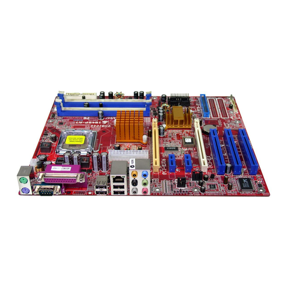
Page 8: Layout And Components
945P-A7 AYOUT AND OMPONENTS JAT XPWR2 JCFAN1 J KBM S1 LGA775 CPU1 JRJ4 5U SB1 Intel Super 945P AUDIO 1 ( 8+ 2C H) JATXPW R1 JAUDIOF 1 PCI-Ex 16 JSPDIF_I N1 SATA4 SATA3 PCI -Ex1_1 (opt ional) ( optio nal) -
Page 9: Chapter 2: Hardware Installation
945P-A7 CHAPTER 2: HARDWARE INSTALLATION (CPU) NSTALLING ENTRAL ROCESSING C o dec Special Notice: Remove Pin Cap before installation, and make good preservation for future use. When the CPU is removed, cover the Pin Cap on the empty socket to ensure pin legs won’t be damaged. - Page 10 945P-A7 Step 2: Look for the triangular cut edge on socket, and the golden dot on CPU should point forwards this triangular cut edge. The CPU will fit only in the correct orientation. Step 2-1: Step 2-2: Step 3: Hold the CPU down firmly, and then lower the lever to locked position to complete the installation.
-
Page 11: Fan Headers
945P-A7 FAN H EADERS These fan headers support cooling-fans built in the computer. The fan cable and connector may be different according to the fan manufacturer. Connect the fan cable to the connector while matching the black wire to pin#1. -
Page 12: Installing System Memory
945P-A7 NSTALLING YSTEM EMORY 1. Unlock a DIMM slot by pressing the retaining clips outward. Align a DIMM on the slot such that the notch on the DIMM matches the break on the Slot. 2. Insert the DIMM vertically and firmly into the slot until the retaining... -
Page 13: Connectors And Slots
945P-A7 ONNECTORS AND LOTS FDD1: Floppy Disk Connector The motherboard provides a standard floppy disk connector that supports 360K, 720K, 1.2M, 1.44M and 2.88M floppy disk types. This connector supports the provided floppy drive ribbon cables. IDE1: Hard Disk Connector (IDE2 and IDE3 are optional.) - Page 14 945P-A7 PCI-Ex16: PCI-Express x16 Slot PCI-Express 1.0a compliant. Maximum theoretical realized bandwidth of 4GB/s simultaneously per direction, for an aggregate of 8GB/s totally. PCI-Ex1_1/PCI-Ex1_2: PCI-Express x1 slots (optional) PCI-Express 1.0a compliant. Data transfer bandwidth up to 250MB/s per direction; 500MB/s in total.
- Page 15 945P-A7 PCI1~PCI3: Peripheral Component Interconnect Slots This motherboard is equipped with 3 standard PCI slots. PCI stands for Peripheral Component Interconnect, and it is a bus standard for expansion cards. This PCI slot is designated as 32 bits. PCI1 PCI2...
-
Page 16: Chapter 3: Headers & Jumpers Setup
945P-A7 CHAPTER 3: HEADERS & JUMPERS SETUP OW TO ETUP UMPERS The illustration shows how to set up jumpers. When the jumper cap is placed on pins, the jumper is “close”, if not, that means the jumper is “open”. Pin opened... - Page 17 945P-A7 JATXPWR2: ATX Power Connector By connecting this connector, it will provide +12V to CPU power circuit. Assignment +12V +12V Ground Ground JSPDIF_OUT1: Digital Audio-out Connector This connector allows user to connect the PCI bracket SPDIF output header. Assignment SPDIF_OUT...
- Page 18 945P-A7 J1394A1 (optional): Header for 1394 Firewire Port at Front Panel Assignment Ground Ground +12V +12V Ground J1394PWR1 (optional): Power Source for 1394 Firewire Port This header allows user to connect the digital image dev ice, like DV , D8, or V8, etc.
- Page 19 945P-A7 AUDIO1: Front Panel Audio Header This header allows user to connect the f ront audio output cable with the PC f ront panel. It will disable the output on back panel audio connectors. Assignment Mic (L) Ground Mic (R)
- Page 20 945P-A7 JKBV1: Power Source Header for PS/2 Keyboard and Mouse Pin 1-2 close (Default) +5V for PS/2 keyboard and mouse. Pin 2-3 close PS/2 keyboard and mouse are powered by +5V standby voltage. Note: In order to support this func tion “Power-on s ystem via keyboar d and mouse”, “JKBV1”...
- Page 21 945P-A7 SATA1~SATA4: Serial ATA Connectors The motherboard has a PCI to SATA Controller with 4 channels SATA interf ace, it satisfies the SATA 2.0 spec and with transfer rate of 3Gb/s. C O M Assignment Ground T X+ SATA4 SATA3...
- Page 22 945P-A7 JCI1: Chassis Open Header This connector allows system to monitor PC case open status. If the signal has been triggered, it will record to the CMOS and show the message on next boot-up. Assignment Case open signal Ground...
-
Page 23: Chapter 4: Useful Help
BIOS contents are corrupted. In this Case, please follow the procedure below to restore the BIOS: Make a bootable floppy disk. Download the Flash Utility “AWDFLASH.exe” from the Biostar website: www.biostar.com.tw Confirm motherboard model and download the respectively BIOS from Biostar website. - Page 24 945P-A7 B. CPU Overheated If the system shutdown automatically after power on system for seconds, that means the CPU protection function has been activated. When the CPU is over heated, the motherboard will shutdown automatically to avoid a damage of the CPU, and the system may not power on again.
-
Page 25: Troubleshooting
945P-A7 ROUBLESHOOTING Problem Solution No power to the system at all Make sure power cable is Power light don’t illuminate, f an securely plugged in. inside power supply does not turn Replace cable. Contact technical support. Indicator light on key board does not turn on. -
Page 26: Chapter 5: Dual Video Function
945P-A7 CHAPTER 5: DUAL VIDEO FUNCTION EQUIREMENTS Only Windows XP supports Dual Video function. Two identical graphics cards that are NVIDIA certified. The graphics card driver should support NVIDIA SLI technology. The power supply unit must provide at least the minimum power required by the system, or the system will be unstable. -
Page 27: Chapter 6: Warpspeeder
945P-A7 WARPSPEEDER™ CHAPTER 6: NTRODUCTION [WarpSpeeder™], a new powerful control utility, features three user-friendly functions including Overclock Manager, Overvoltage Manager, and Hardware Monitor. With the Overclock Manager, users can easily adjust the frequency they prefer or they can get the best CPU performance with just one click. The Overvoltage Manager, on the other hand, helps to power up CPU core voltage and Memory voltage. -
Page 28: Installation
945P-A7 NSTALLATION 1. Execute the setup execution file, and then the following dialog will pop up. Please click “Next” button and follow the default procedure to install. 2. When you see the following dialog in setup procedure, it means setup is completed. -
Page 29: Warpspeeder™] Includes 1 Tray Icon And 5 Panels
945P-A7 ™] PEEDER INCLUDES TRAY ICON AND PANELS 1. Tray Icon: Whenever the Tray Icon utility is launched, it will display a little tray icon on the right side of Windows Taskbar. This utility is responsible for conveniently invoking [WarpSpeeder™] Utility. - Page 30 945P-A7 2. Main Panel If you click the tray icon, [WarpSpeeder™] utility will be invoked. Please refer to the following figure; the utility’s first window you will see is Main Panel. Main Panel contains fe ature s as follows: a. Display the CPU Speed, CPU external clock, Memory clock, AGP clock, and PCI clock information.
- Page 31 945P-A7 3. Voltage Panel Click the Voltage button in Main Panel, the button will be highlighted and the Voltage Panel will slide out to up as the following figure. In this panel, you can decide to increase CPU core voltage and Memory voltage or not.
- Page 32 945P-A7 4. Overclock Panel Click the Overclock button in Main Panel, the button will be highlighted and the Overclock Panel will slide out to left as the following figure. O ve rclock Panel contains the these features: a. “–3MHz button”, “-1MHz button”, “+1MHz button”, and “+3MHz button”: provide user the ability to do real-time overclock adjustment.
- Page 33 945P-A7 “Auto-overclock button”: User can click this button and [WarpSpeeder™] will set the best and stable performance and frequency automatically. [WarpSpeeder™] utility will execute a series of testing until system fail. Then system will do fail-safe reboot by using Watchdog function. After reboot, the [WarpSpeeder™] utility will restore to the hardware default...
- Page 34 945P-A7 6. About Panel Click the “about” button in Main Panel, the button will be highlighted and the About Panel will slide out to up as the following figure. In this panel, you can get model name and detail information in hints of all the chipset that are related to overclocking.
- Page 35 945P-A7 Note : Because the overclock, overvoltage, and hardware monitor features are controlled by several separate chipset, [WarpSpeeder™] divide these features to separate panels. If one chipset is not on board, the correlative button in Main panel will be disabled, but will not interfere other panels’...
- Page 36 945P-A7 BIOS SETUP BIOS Setup..................1 1 Main Menu..................... 3 2 Standard CMOS Features ................6 3 Advanced BIOS Features................9 4 Advanced Chipset Features................15 5 Integrated Peripherals .................. 18 6 Power Management Setup ................25 7 PnP/PCI Configurations ................31 8 PC Health Status ..................
-
Page 37: Bios Setup
945P-A7 BIOS Manual BIOS Setup Introduction This manual discussed Award™ Setup program built into the ROM BIOS. The Setup program allows users to modify the basic system configuration. This special information is then stored in battery-backed RAM so that it retains the Setup information when the power is turned off. - Page 38 945P-A7 BIOS Manual PCI Bus Support This AWARD BIOS also supports Version 2.1 of the Intel PCI (Peripheral Component Interconnect) local bus specification. DRAM Support DDR SDRAM (Double Data Rate Synchronous DRAM) are supported. Supported CPUs This AWARD BIOS supports the Intel CPU.
-
Page 39: Main Menu
945P-A7 BIOS Manual 1 Main Menu Once you enter Award BIOS™ CMOS Setup Utility, the Main Menu will appear on the screen. The Main Menu allows you to select from several setup functions. Use the arrow keys to select among the items and press <Enter> to accept and enter the sub-menu. - Page 40 945P-A7 BIOS Manual Integrated Peripherals This submenu allows you to configure certain IDE hard drive options and Programmed Input/ Output features. Power Management Setup This submenu allows you to configure the power management features. PnP/PCI Configurations This submenu allows you to configure certain “Plug and Play” and PCI options.
- Page 41 945P-A7 BIOS Manual Set User Password If the Supervisor Password is not set, then the User Password will function in the same way as the Supervisor Password. If the Supervisor Password is set and the User Password is set, the “User” will only be able to view configurations but will not be able to change them.
-
Page 42: Standard Cmos Features
945P-A7 BIOS Manual 2 Standard CMOS Features The items in Standard CMOS Setup Menu are divided into 10 categories. Each category includes no, one or more than one setup items. Use the arrow keys to highlight the item and then use the<PgUp> or <PgDn> keys to select the value you want in each item. - Page 43 945P-A7 BIOS Manual Main Menu Selections This table shows the selections that you can make on the Main Menu. Item Options Description Date mm : dd : yy Set the system date. Note that the ‘Day’ automatically changes when you set the date.
- Page 44 945P-A7 BIOS Manual Item Options Description Halt On All Errors Select the situation in which No Errors you want the BIOS to stop All, but Keyboard the POST process and All, but Diskette notify you. All, but Disk/ Key Base Memory...
-
Page 45: Advanced Bios Features
945P-A7 BIOS Manual 3 Advanced BIOS Features Figure 3. Advanced BIOS Setup... - Page 46 945P-A7 BIOS Manual CPU FEATURE Delay Prior to Thermal Set this item to enable the CPU Thermal function to engage after the specified time. The Choices: 4Min, 8Min, 16Min (default), 32Min. Thermal Management Allow you to choose the thermal management method of your monitor.
- Page 47 945P-A7 BIOS Manual C1E Function CPU C1E Function select. The Choices: Auto (default) Execute Disable Bit When disabled, forces the XD feature flag to always return 0. The Choices: Enabled (default), Disabled. Virtualization Technology When enabled, a VMM can utilize the additional hardware Capabilities provided by vanderpool Technology.
- Page 48 945P-A7 BIOS Manual Hard Disk Boot Priority These BIOS attempt to load the operating system from the device in the sequence selected in these items. The Choices: Pri. Master, Pri.Slave, Sec.Master, Sec. Slave, USBHDD0, USBHDD1, USBHDD2 and Bootable Add-in Carde.
- Page 49 945P-A7 BIOS Manual VIRUS WARNING This option allows you to choose the Virus Warning feature that is used to protect the IDE Hard Disk boot sector. If this function is enabled and an attempt is made to write to the boot sector, BIOS will display a warning message on the screen and sound an alarm beep.
- Page 50 945P-A7 BIOS Manual SECURITY OPTION This option will enable only individuals with passwords to bring the system online and/or to use the CMOS Setup Utility. System A password is required for the system to boot and is also required to access the Setup Utility.
-
Page 51: Advanced Chipset Features
945P-A7 BIOS Manual 4 Advanced Chipset Features This submenu allows you to configure the specific features of the chipset installed on your system. This chipset manage bus speeds and access to system memory resources, such as DRAM. It also coordinates communications with the PCI bus. The default settings that came with your system have been optimized and therefore should not be changed unless you are suspicious that the settings have been changed incorrectly. - Page 52 945P-A7 BIOS Manual DRAM RAS# PRECHARGE If an insufficient number of cycles is allowed for RAS to accumulate its charge before DRAM refresh, the refresh may be incomplete, and the DRAM may fail to retain data. Fast gives faster performance; and Slow gives more stable performance.
- Page 53 945P-A7 BIOS Manual PCI EXPRESS ROOT PORT FUNC PCI Express Port 1/ 2/3 This item allows you to select the PCI Express Port. The Choices: Auto (default), Enabled, Disabled. PCI-E Compliancy Mode This item allows you to select the PCI-E Compliancy Mode.
-
Page 54: Integrated Peripherals
945P-A7 BIOS Manual 5 Integrated Peripherals Figure 5. Integrated Peripherals... - Page 55 945P-A7 BIOS Manual ONCHIP IDE DEVICE IDE HDD Block Mode Block mode is also called block transfer, multiple commands, or multiple sector read / write. If your IDE hard drive supports block mode (most new drives do), select Enabled for automatic detection of the optimal number of block mode (most new drives do), select Enabled for automatic detection of the optimal number of block read / write per sector where the drive can support.
- Page 56 945P-A7 BIOS Manual On-chip Secondary PCI IDE This item allows you to enable or disable the primary/ secondary IDE Channel. The Choices: Enabled (default), Disabled. IDE Primary/Secondary/Master/Slave UDMA Ultra DMA/100 functionality can be implemented if it is supported by the IDE hard drives in your system. As well, your operating environment requires a DMA driver (Windows 95 OSR2 or a third party IDE bus master driver).
- Page 57 945P-A7 BIOS Manual ON BOARD DEVICE USB Controller Select Enabled if your system contains a Universal Serial Bus (USB) controller and you have USB peripherals. The Choices: Enabled (default), Disabled USB 2.0 Controller This entry is to enabled/ disabled EHCI controller only. This BIOS itself may/ may not have high speed USB support.
- Page 58 945P-A7 BIOS Manual Onboard RAID <ITE8211> This item allows you to enable or disable to support Onboard RAID (ITE8211). The Choices: Enabled (default), Disabled. Onboard RAID BIOS This item allows you to enable or disable to Onboard RAID BIOS. The Choices: Enabled (default), Disabled.
- Page 59 945P-A7 BIOS Manual SUPER IO DEVICE Super IO Device If you highlight the literal “Press Enter” next to the “ ” label and then press the enter key, it will take you a submenu with the following options: Onboard FDC Controller Select Enabled if your system has a floppy disk controller (FDC) installed on the system board and you wish to use it.
- Page 60 945P-A7 BIOS Manual Onboard Parallel Port This item allows you to determine access onboard parallel port controller with which I/O Address. The Choices: 378/IRQ7 (default), 278/IRQ5, 3BC/IRQ7, Disabled. Parallel Port Mode The default value is SPP. The Choices: SPP (default) Using Parallel port as Standard Printer Port.
-
Page 61: Power Management Setup
945P-A7 BIOS Manual 6 Power Management Setup The Power Management Setup Menu allows you to configure your system to utilize energy conservation and power up/power down features. Figure 6. Power Management Setup... - Page 62 945P-A7 BIOS Manual ACPI & WAKE UP EVENTS ACPI Function This item displays the status of the Advanced Configuration and Power Management (ACPI). The Choices: Enabled (default), Disabled. ACPI Suspend Type The item allows you to select the suspend type under the ACPI operating system.
- Page 63 945P-A7 BIOS Manual Wake-Up by PCI card When you select “Enable”, a PME signal from PCI card returns the system to Full On state. The Choices: Enabled, Disabled (default). Power On by Ring An input signal on the serial Ring Indicator (RI) line (in other words, an incoming call on the modem) awakens the system from a soft off state.
- Page 64 945P-A7 BIOS Manual RELOAD TIMER EVENTS Primary/Secondary IDE 0/1 You can select to enable or disable Primary or Secondary RAID 0 or RAID 1 function under this item. The Choices: Disabled (default), Enabled. FDD, COM, LPT Port You can select to enable or disable FDD, COM, and LPT port under this item.
- Page 65 945P-A7 BIOS Manual POWER MANAGEMENT This category allows you to select the type (or degree) of power saving and is directly related to the following modes: 1.HDD Power Down. 2.Suspend Mode. There are four options of Power Management, three of which have fixed mode settings Min.
- Page 66 945P-A7 BIOS Manual SUSPEND MODE The item allows you to select the suspend type under ACPI operating system. The Choices: Disabled (default), 1 Min, 2 Min, 4 Min, 6 Min, 8 Min, 10 Min, 20 Min, 30 Min, 40 Min, 1 Hour.
-
Page 67: Pnp/Pci Configurations
945P-A7 BIOS Manual 7 PnP/PCI Configurations This section describes configuring the PCI bus system. PCI, or Personal Computer Interconnect, is a system which allows I/O devices to operate at speeds nearing the speed of the CPU itself uses when communicating with its own special components. This section covers some very technical items and it is strongly recommended that only experienced users should make any changes to the default settings. - Page 68 945P-A7 BIOS Manual IRQ RESOURCES This submenu will allow you to assign each system interrupt a type, depending on the type of device using the interrupt. When you press the “Press Enter” tag, you will be directed to a submenu that will allow you to configure the system interrupts.
-
Page 69: Pc Health Status
945P-A7 BIOS Manual 8 PC Health Status Figure 8. PC Health Status SHUTDOWN TEMPERATURE This item allows you to set up the CPU shutdown Temperature. This item only effective under Windows 98 ACPI mode The Choices: 60 C/140 F, 65... -
Page 70: Frequency Control
945P-A7 BIOS Manual 9 Frequency Control Figure 9. Frequency Control CPU CLOCK RATIO This item allows you to select the CPU Ratio. The Choices: 8X (default), 9X, 10X, 11X, 12X, 13X, 14 X, 15X, 16X, 17X, 18X, 19X, 20 X, 21 X, 22 X, and 23X. - Page 71 945P-A7 BIOS Manual CPU CLOCK This item allows you to select CPU Clock, and CPU over clocking. The Choices: 100MHZ (default). Special Notice: If unfortunately, the system’s frequency that you are selected is not functioning, there are two methods of booting-up the system.