Table of Contents
Advertisement
Quick Links
http://au.lge.com (Australia)
http://nz.lge.com (New Zealand)
Built-In Gas Cooktops
Installation and Operating Instructions
To avoid the risk of accidents or damage to the Gas Cooktops,
it is essential to read these operating instructions
before it is installed or used for the first time.
And please keep this manual for later reference.
HB7522A
P/No.: MFL62060302
Advertisement
Table of Contents

Related Manuals for LG HB7522A


Summary of Contents for LG HB7522A
- Page 1 (New Zealand) Built-In Gas Cooktops Installation and Operating Instructions HB7522A To avoid the risk of accidents or damage to the Gas Cooktops, it is essential to read these operating instructions before it is installed or used for the first time.
-
Page 2: Table Of Contents
Contents Introduction ................. 3 1. Instructions for safe and proper use ........3 Instructions for the installer ............5 2. Positioning of the hob ............. 5 3. Electrical connection .............. 9 4. Gas connection ..............10 5. Adaptation to different types of gas ........12 6. -
Page 3: Introduction
Introduction 1. Instructions for safe and proper use This manual is an integral part of the appliance and therefore must be kept in its entirety and in an accessible place for the whole working life of the cooking hob. We advise reading this manual and all the instructions therein before using the cooking hob. - Page 4 Introduction The identification plate, with technical data, serial number and marking is clearly visible under the casing. The plate on the casing must not be removed. Before connecting the device, make sure that it has been regulated for the type of gas that will feed it, checking the label under the casing. Do not put pans without perfectly smooth and flat bottoms on the cooking hob grids.
-
Page 5: Instructions For The Installer
Instructions for the installer 2. Positioning of hob This appliance shall be installed only by authorized persons in accordance with AS5601 - Gas Installations, any statutory regulations, local gas regulations, municipal building codes, electrical wiring regulations, and the manufacturer's installation instructions. - Page 6 Instructions for the installer The distances in the following drawing refer to the hole on the inner side of the gasket. In case of installation on a hollow compartment with doors, a separating panel has to be placed under the hob. Keep a minimum distance of 10 mm between the bottom of the unit and the panel surface.
- Page 7 2.2 Clearance above and around domestic appliances Extract from AS5601 REQUIREMENTS 1 Overhead clearances – (Measurement A) Range hoods and exhaust fans shall be installed in accordance with the manufacturer’s instructions. However, in no case shall the clearance between the highest part of the hob of the cooking appliance and a range hood be less than 600 mm or, for an overhead exhaust fan, 750 mm.
- Page 8 Instructions for the installer 2 Side clearances – (Measurements B & C) Where B, measured from the periphery of the nearest burner to any vertical combustible surface, is less than 200 mm, the surface shall be protected in accordance with Clause 5.12.1.2 to a height C of not less than 150 mm above the hob for the full dimension (width or depth) of the cooking surface area.
-
Page 9: Electrical Connection
3. Electrical connection Make sure that the voltage and capacity of the power line conform to the data shown on the plate located under the casing. Do not remove this plate for any reason. The plug on the end of the supply cable and the wall socket must be the same type and conform to the current electrical system regulations. -
Page 10: Gas Connection
Instructions for the installer 4. Gas connection Use pipe-joint compound made for use with Natural U.L.P. gas. The burner it controls is shown next to each knob (the example corresponds to the front left burner). This appliance is suitable for installation with Natural Gas or ULPG (propane). - Page 11 be installed. The N.G. regulator must be checked and adjusted to 1.0kPa after installation. U.L.P.G. Can be connected to the inlet fitting directly. The pressure must be checked to ensure it is operating at 2.75kPa. A separate test point fitting must be installed between the piping &...
-
Page 12: Adaptation To Different Types Of Gas
Instructions for the installer 5. Adaptation to different types of gas Before performing any cleaning or maintenance work, detach the appliance from the electrical socket. The hob has been adjusted for natural gas at a pressure of 1.0kPa. For functioning with other types of gas the nozzles must be replaced and the primary air adjusted. - Page 13 5.2 Regulation for ULPG Loosen screw A and push support B all the way. Use a double head wrench to remove nozzle C and assemble the suitable one, following the instructions indicated in the reference charts, with respect to the type of gas to use. The screwing torque of the nozzle should never exceed 3 Nm.
- Page 14 Instructions for the installer 5.3 Regulation for natural gas The hob has been adjusted for natural gas at a pressure of 1.0kPa. To allow the unit to work with this type of gas, perform the same operations described in paragraph “5.2 Regulation for ULPG”, but choose the nozzles and regulate the primary air for natural gas, as shown in the following table and in paragraph “5.4 Regulation of primary air”.
-
Page 15: Final Operations
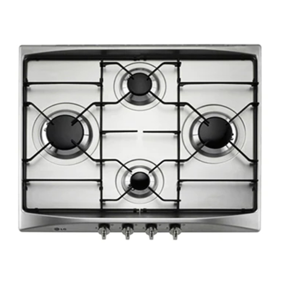
6. Final operations Having carried out the above adjustments, reassemble the appliance following, backwards, the instructions in paragraph “5.1 Removing the hob”. 6.1 Regulation of minimum for natural gas Replace the components on the burner and slide the knobs on the gas tap pins. Light the burner and set it at minimum position. - Page 16 Instructions for the installer 6.3 Arrangement of burners on hob BURNERS 1. Auxiliary 2. Semi rapid 3. Rapid 4. Wok 6.4 Lubrication of gas taps After a while, the gas tap may become hard to turn or lock. If this happens, it has to be cleaned inside and re-greased.
-
Page 17: Instructions For The User
Instructions for the user 7. Using the hob Make sure that the flame-baffle crowns, the caps and the grid have been assembled correctly. Grid C (supplied) should be used for “woks” (Chinese pots). Adapter B (supplied) is to be used for small vessels. 7.1 Ignition of the burners with safety device For each knob the corresponding burner is indicated. - Page 18 Instructions for the user All containers have to have a flat and smooth bottom. When using fats or oils, be extremely careful that they don’t overheat and catch fire. If the flame accidentally goes out, turn off the control knob and wait at least 1 minute before trying to re-light the burner.
-
Page 19: Cleaning And Maintenance
8. Cleaning and maintenance Never use a steam jet to clean the appliance. Before any intervention, disconnect the power supply of the device. 8.1 Cleaning Clean the cooking top regularly every time you use it, obviously after it has cooled. 8.1.1 Regular daily cleaning of the hob In order to clean and preserve the surface, always use specific products only, which do not contain abrasive substances or... - Page 20 Instructions for the user CAUTION: do not wash these components in a dishwasher. In normal use of the hob, the stainless steel burner caps and pan- stands tend to be burnished by the high temperature. Clean these parts using very fine abrasive sponges or similar commercial products.
- Page 21 FOR WARRANTY SERVICE PLEASE CONTACT LG Service on 1300 LG CARE (1300 54 2273) AUSTRALIA or 0800 LG CARE (0800 54 2273) NEW ZEALAND LG Electronics Australia 2 Wonderland Drive Eastern Creek NSW 2766 (ABN : 98 064 531 264)