
Related Manuals for Acer Veriton S480G


Summary of Contents for Acer Veriton S480G
- Page 1 Veriton S480G/S488G/S480 Service Guide Service guide files and updates are available on the AIPG/CSD web; for more information please refer to http://csd.acer.com.tw PRINTED IN TAIWAN...
-
Page 2: Revision History
Revision History Please refer to the table below for the updates made on Veriton S480G/S488G/S480 Service Guide. Date Chapter Updates... - Page 3 Copyright Copyright © 2009 by Acer Incorporated. All rights reserved. No part of this publication may be reproduced, transmitted, transcribed, stored in a retrieval system, or translated into any language or computer language, in any form or by any means, electronic, mechanical, magnetic, optical, chemical, manual or otherwise, without the prior written permission of Acer Incorporated.
- Page 4 Conventions The following conventions are used in this manual: SCREEN Denotes actual messages that appear on MESSAGES screen. Gives bits and pieces of additional information NOTE related to the current topic. WARNING Alerts you to any damage that might result from doing or not doing specific actions.
- Page 5 ACER-AUTHORIZED SERVICE PROVIDERS, your Acer office may have a DIFFERENT part number code to those given in the FRU list of this printed Service Guide. You MUST use the list provided by your regional Acer office to order FRU parts for repair and service of customer machines.
-
Page 6: Table Of Contents
Chapter 1 System Specifications 1 F e a t u r e s … … … … … … … … … … … … … … … … … … … … … … … … … … … … … … … … … … … . . . 1 B l o c k D i a g r a m …... -
Page 7: Chapter 1 System Specifications
System Specifications Features Operating System Microsoft Windows Vista Home Basic SP1 Microsoft Windows Vista Business SP1(32bit) Microsoft Windows Vista Business SP1(64bit) Microsoft Windows XP Professional SP3 Linpus Linux X Window mode FreeDOS Microsoft Windows Vista Home Premium SP1(32bit)(Only for Extensa) Processor Socket Type: Intel®... - Page 8 PCI Express Slot Type: x16 PCI Express x16 Slot Quantity: 1 PCI Express Slot Type: x1 PCI Express x1 Slot Quantity: 1 PCI Slot Type: PCI 2.25V Quantity: 2 Slot Quantity: 1 Design Criteria: Should support 1.44MB/3 mode 3.5” Devices SATA Slot Type: SATA slot Slot Quantity: 6...
- Page 9 2 ports for internal card reader Connector Pin: standard Intel FPIO pin definition Data transfer rate support: USB 2.0/1.1 Design Criteria: Should meet Acer USB drop criteria BIOS BIOS Type: AMI Kernel with Gateway skin Size: 4Mb/8MB Note: Boot ROM should be included (PXE function should be built in with default and...
- Page 10 1 Serial port 1 D-Sub VGA port 1 DVI-D port 1 RJ45 LAN port, 6 USB ports 1 1394 port 5.1 channel phone jack (3 audio jacks) On-board connectors 1 CPU socket 4 DDR-3 memory sockets 1 PCI Express x16 slot 1 PCI Express x 1 slots 2 PCI slots 6 SATAII connectors(Need to confirm no interfere with gfx card)
-
Page 11: Power Supply
Features for internal mounting tab Location of 4 external mounting holes Power Supply Electrical Design Feature 300W/250W in stable mode (Acer Assign System Power Unit) Voltage design should be covered +5V, +3.3V, +12V, +5VSB, -12V (attention to 12V output capability) -
Page 12: Block Diagram
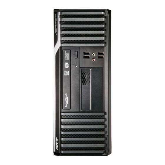
Block Diagram Block Diagram VRD 11 Intel LGA775 Processor ISL6333 3-Phase PWM PCI_E X16 PCI EXPRESS X16 SLOT Connector PCI EXPRESS X4 Analog Video Out PCI_E x1 PCI_E x1 SATA-II 1~6 SATA2 USB Port 1~12 USB2.0 SPI 8M FLASH ROM FSB 800/1066/1333 4 DDR III DIMM... - Page 13 Veriton S480G/S488G/S480 Front Panel The computer’s front panel consists of the following: Label Card reader USB and audio jack ports Acer Logo Optical drive Power Button Description...
-
Page 14: Veriton S480G/S488G/S480 Rear Panel
Veriton S480G/S488G/S480 Rear Panel Label Description Power card socket PS/2 keyboard connecter Serial port DVI-D port USB 2.0 connector Audio connector Label Description Fan aperture PS/2 mouse connecter D-Sub port COM2 port Print port LAN connector... -
Page 15: Hardware Specifications And Configurations
Hardware Specifications and Configurations Processor Item Type Socket Minimum operating speed BIOS Item BIOS code programmer BIOS version BIOS ROM type BIOS ROM size Support protocol Device Boot Support Support to LS-120 drive Support to BIOS boot block feature Specification Intel Socket T LGA 775 pin LGA 775 pin 800/1066/1333 MHz... -
Page 16: Bios Hotkey List
BIOS Hotkey List Hotkey Function Enter BIOS Setup Utility Main Board Major Chips Item North Bridge Intel G43 South Bridge ICH 10R APG controller Intel G43 Super I/O controller ITE 8720 Audio controller Realtek HD audio codec ALC662-VC HD codec 5.1 LAN controller Marvel 88E8071 HDD controller... -
Page 17: Memory Combinations
Memory Combinations Slot Memory Slot 1 1GB, 2GB Slot 2 1GB, 2GB Slot 3 1GB, 2GB Slot 4 1GB, 2GB Maximum System Memory Supported System Memory Item Memory slot number Support Memory size per socket Support memory type Support memory interface Support memory voltage Support memory module package Support to parity check feature... -
Page 18: Audio Interface
Audio Interface Item Audio controller Audio controller type Audio channel Audio function control Mono or stereo Compatibility Music synthesizer Sampling rate MPU-401 UART support Microphone jack Headphone jack Specification Intel ICH 10R ALC662-VC HD codec 5.1 Enable/disable by BIOS Setup Stereo Sound Blaster Pro/16 compatible Mixed digital and analog high... -
Page 19: Sata Interface
SATA Interface Item SATA controller SATA controller resident bus Number of SATA channel Support bootable CD-ROM USB Port Item Universal HCI USB Class USB Connectors Quantity Specification Intel ICH 10R PCI bus SATA X 6 Specification USB 2.0/1.1 Support legacy keyboard for legacy mode 6 back panel ports 4 ports for front daughter board... -
Page 20: Environmental Requirements
Environmental Requirements Item Temperature Operating Non-operating Humidity Operating Non-operating Vibration Operating (unpacked) Specification +5°C ~ +35°C -20 ~ +60°C (Storage package) 15% to 80% RH 10% to 90% RH 5 ~ 500 Hz: 2.20g RMS random, 10 minutes per axis in all 3 axes 5 ~500 Hz: 1.09g RMS random, 1 hour per axis in all 3 axes... -
Page 21: Power Management
Power Management Devices Power Button Keyboard/Mouse Devices wake up from S3 should be less than Devices wake up from S5 should be less than 10 seconds Disabled Disabled Disabled Disabled Disabled Disabled Disabled Disabled Disabled Disabled Disabled Disabled... -
Page 22: P O W E R M A N A G E M E N T F U N C T I O N ( A C P I S U P P O R T F U N C T I O
Power Management Function(ACPI support function) Device Standby Mode Independent power management timer for hard disk drive devices(0-15 minutes,time step=1minute). Hard Disk drive goes into Standby mode(for ATA standard interface). Disable V-sync to control the VESA DPMS monitor. Resume method:device activated (keyboard for DOS, keyboard &mouse for Windows. -
Page 23: Chapter 2 System Utilities
Chapter 2 System Utilities The manufacturer or the dealer already configures most systems. There is no need to run Setup when starting the computer unless you get a Run Setup message. The Setup program loads configuration values into the battery-backed nonvolatile memory called CMOS RAM. -
Page 24: E N T E R I N G S E T U
Entering Setup Power on the computer and the system will start POST (Power On Self Test) process. When the message of key of [Delete] to enter the setup menu. NOTE: If the message disappears before you respond and you still wish to enter Setup, restart the system by turning it OFF and On. - Page 25 The items in the main menu are explained below: Parameter Production Information Standard CMOS Features Advance BIOS Features Advance Chipset Features Integrated Peripherals Power Management Setup PC Health Status Frequency/Voltage Control BIOS Security Features Load Optimized Defaults Save & Exit Setup Exit Without Saving Description This page shows the relevant information of the main...
-
Page 26: P R O D U C T I N F O R M A T I O
System Manufacturer Product Name System Serial Number System BIOS Version BIOS Release Date Product Information 2.5GHZ 4.96MHZ :Acer : Veriton M480 :P01-A0 : 04/10/2009 +/-/: Value F9: Optimized Defaults Description This item lists the Processor Type This item lists the Processor speed... -
Page 27: Standard Cmos Setup
Standard CMOS Setup Select standard CMOS features from the main menu to configure some basic parameters in your system the following screen shows the standard CMOS features menu: CMOS Setup Utility – Copyright (c) 1985-2005,American Megatrends, Inc. System Date System Time Floppy A ACPI Port 1 ACPI Port 2... - Page 28 The following table describes the parameters found in this menu. Parameter System Date To set the date following weekday-month-date-year format System Time To set the time following the hour-minute-second format Halt On This item enables use to select the situation if the BIOS stops the POST process and the notification...
-
Page 29: A D V A N C E D B I O S F E A T U R E
Advanced Setup The following screen shows the Advanced Setup: CMOS Setup Utility Copyright (c) 1985-2008,American Megatrends, Inc. Quick Boot Quiet Boot 1st Boot Device 2nd Boot Device 3rd Boot Device 4th Boot Device Hard Disk Drive Priority Optical Disk Device Priority [Press Enter] Removable Device Priority [Press Enter] Boot up Num-Lock BIOS Write Protect... -
Page 30: Advanced Chipset Setup
Advanced Chipset Setup CMOS Setup Utility Copyright (c) 1985-2008,American Megatrends, Inc Intel EIST Intel XD Bit Intel VT Memory Hole Remapping Primary Video Video Memory Size DUMT Mode DUMT/Fixed Memory Size : Move Enter: Select F1: General Help The following table describes the parameters found in this menu. Parameter Intel EIST For Intel platform... -
Page 31: I N T E G R A T E D P E R I P H E R A L
Integrated Peripherals CMOS Setup Utility – Copyright (c) 1985-2008, American Megatrends, Inc. Onboard SATA Mode Onboard USB Controller Legacy USB Support USB Storage Emulation Onboard Graphics Controller Onboard Audio Controller Onboard LAN Controller Onboard LAN Option ROM Onboard Floppy Controller Serial Port1 Address Serial Port2 Address Serial Port2 Mode... - Page 32 The following table describes the parameters found in this menu. Parameter Onboard SATA Mode Onboard USB Controller Legacy USB Support Onboard Audio Controller Onboard LAN Controller Onboard LAN Option ROM Onboard Floppy Controller Serial Port1 Address Serial Port2 Address Serial Port2 Mode Description This item is only available when onboard SATA controller is enabled...
- Page 33 Power Management The Power Management menu lets you configure your system to most effectively save energy while operating in a manner consistent with your own style of computer use. The following screen shows the Power Management parameters and their default settings: CMOS Setup Utility–...
-
Page 34: P C H E A L T H S T A T U
PC Health Status CMOS Setup Utility– Copyright (c) 1985-2008,American Megatrends, Inc. CPU Temperature (PECI Mode) System Temperature CPU Fan Speed System Fan Speed CPU Core +1.1V +3.30V +5.00V +12.0V 5VSB VBAT CPU Shutdown Temperature System Shutdown Temperature Smart Fan : Move Enter: Select F1: General Help The following table describes the parameters found in this menu: Parameter... -
Page 35: F R E Q U E N C Y / V O L T A G E C O N T R O
Frequency/Voltage Control CMOS Setup Utility– Copyright (c) 1985-2008,American Megatrends, Inc Enable Clock to All PCI/PCIE Spread Spectrum : Move Enter: Select F1: General Help The following table describes the parameters found in this menu: Parameter Spread Spectrum Frequency/Voltage Control Enabled Enabled Disabled Enabled... -
Page 36: B I O S S E C U R I T Y F E A T U R E
BIOS Security Features CMOS Setup Utility – Copyright (c) 1985-2008,American Megatrends, Inc. Supervisor Password User Password HDD Password Change Supervisor Password Change User Password Change HDD Password Removable Device Boot Chassis Opened Warning Chassis Opened : Move Enter: Select F1: General Help The following table describes the parameters found in this menu: Parameter Change Supervisor... -
Page 37: L O A D D E F A U L T S E T T I N G
Load Default Settings This option opens a dialog box that lets you install defaults for all appropriate items in the Setup Utility. CMOS Setup Utility – Copyright (c) 1985-2008,American Megatrends, Inc. Product Information Standard CMOS Features Advance BIOS Features Advanced Chipset Features Integrated Peripherals Power Management Setup : Move Enter: Select... -
Page 38: S A V E & E X I T S E T U
Save & Exit Setup Highlight this item and press <Enter> to save the changes that you have made in the Setup Utility and exit the Setup Utility. CMOS Setup Utility – Copyright (c) 1985-2008,American Megatrends, Inc. Product Information Standard CMOS Features Advance BIOS Features Advanced Chipset Features Integrated Peripherals... -
Page 39: E X I T W I T H O U T S A V I N
Exit Without Saving Highlight this item and press <Enter> to discard any changes that you have made in the Setup Utility and exit the Setup Utility. CMOS Setup Utility – Copyright (c) 1985-2008,American Megatrends, Inc. Product Information Standard CMOS Features CMOS Advance BIOS Features Advanced Chipset Features... -
Page 40: Chapter 3 Machine Disassembly And Replacement
Machine Disassembly and Replacement To disassemble the computer, you need the following tools: Wrist grounding strap and conductive mat for preventing electrostatic discharge. Wire cutter. Phillips screwdriver (may require different size). NOTE: The screws for the different components vary in size. During the disassembly process, group the screws with the corresponding components to avoid mismatches when putting back the components. -
Page 41: G E N E R A L I N F O R M A T I O
General Information Before You Begin Before proceeding with the disassembly procedure, make sure that you do the following: 1. Turn off the power to the system and all peripherals. 2. 2.Unplug the AC adapter and all power and signal cables from the system... -
Page 42: D I S A S S E M B L Y P R O C E D U R
Disassembly Procedure This section tells you how to disassemble the system when you need to perform system service. Please also refer to the disassembly video, if available. CAUTION: Before you proceed, make sure you have turned off the system and all peripherals connected to it. - Page 43 Russian Blue Veriton S480G/S488G/S480 Standard Disassembly Process Bezel Process: 1. According to the requirement, paste ATI, OS, CPU, HDMI and marketing label by SKU.
-
Page 44: Remove Side Cover
Remove side cover Process: 1. Put the Computer on the worktable lightly. 2. Release left side cover with 3 screws then remove left side cover. Remove CPU fan pipe Process: 1. Release the CPU fan pipe. -
Page 45: Remove Cards
Remove Cards Process: 1. Release the slot cover tooless 2. Remove VGA 、 TV、 Modem Card,the following list is for your reference about the mutual location relation (Optional by SKU). Remove HDD Data Cables Process: 1. Remove master HDD data cable from M/B SATA1/SATA3. 2. -
Page 46: Remove Odd Data Cable
Remove ODD DATA cable Process: 1. Remove master ODD data/power cable from Master ODD. Remove HDD power cable Process: 1. Remove master HDD data cable from master HDD. 2. Remove slave HDD data cable from slave HDD... -
Page 47: Remove Cables
Remove Cables Process: 1. Remove front panel light cable from“PANEL1” slot of M/B. 2. Remove USB1 cable from M/B”F_ USB3”。 3. Remove USB2 cable from M/B”F_ USB4”。 4. Remove Card reader cable from M/B”USB2”. 5. Remove audio cable from the “AUDIO” port on M/B. Remove HDD... -
Page 48: Remove Fdd Cable
Process: 1. Remove Master HDD from the first HDD location. 2. Remove Slave HDD from the second HDD location. (Optional by SKU) Remove FDD Cable... -
Page 49: Remove Card Reader
Process: 1. Remove FDD digital cable just as pictures (Optional by SKU). 2. Plug 4 pins power cord from FDD slot. 3. Remove front bezel light cable from PATA power cable Remove card reader Process: 1. Remove card reader from chassis. -
Page 50: Remove Odd
Remove ODD Process: 1. Push the lock handle release ODD. 2. Remove ODD from the location. Remove Cables Process: 1. Remove M/B power cable from M/B “ATX1”. 2. Remove 12 V power cable from M/B” JPW1” 3. Remove System Fan cable from M/B”SYS-F2”. MB power cable... -
Page 51: Remove System Fan
Remove System FAN Process: 1. Release four screws according to the following picture. Remove mother board Process:... -
Page 52: Remove Cpu Cooler
1. Release 8 pcs screws form the corresponding hole. 2. Release screws according to the following picture in turn. 3. Remove the Mother board from chassis. Remove CPU cooler Process: 1. Remove cooler power cable from M/B “CPU-F2”. 2. Release screw 1 first, then fixes screw 2, screw 3 & screw 4 (As Picture). 3. -
Page 53: Remove Cpu
1. Remove the first Memory from DIMM. 2. Remove the second Memory from DIMM2 (Optional by SKU). Process: 1. Remove CPU according following the pictures. Process: Remove CPU Open the Handle Remove I/O shielding... - Page 54 1. Remove I/O Shielding.
-
Page 55: Chapter 4 Troubleshooting
Troubleshooting Please refer to generic troubleshooting guide for troubleshooting information relating to following topics: Power-On Self-Test (POST) POST Check Points POST Error Messages List Error Symptoms List Chapter 4... - Page 56 Chapter 5...
- Page 58 ATX_POWER: ATX 24-pin Power Connector Signal Name +3.3 +3.3 PWR OK 5VSB +12V +12V +3.3V Signal Name +3.3V -12V PS_ON...
-
Page 62: Chapter 6 Fru (Field Replaceable Unit) List
DIFFERENT part number code to those given in the FRU list of this printed Service Guide. You MUST use the local FRU list provided by your regional Acer office to order FRU parts for repair and service of customer machines. -
Page 63: E X P L O D E D D I A G R A
Exploded Diagram DESCRIPTION POWER SUPPLY ACER-16L-BASE HDD-MOUDLE HDD-CAGE USB-MOUDLE LENS-HOLDER MAIN-BEZEL FRONT-STRIP FDD-COVER ODD-COVER UP-BEZEL DESCRIPTION HOLDER-SWITCH ODD-CAGE ACER-16L-FRONT-CHASSIS ACER-16L-ODD-SUPPORT-BKT ACER-16L-SUPPORT ACER-16L-CHASSIS-SUPPORT ACER-16L-TOP-COVER ACER-16L-FAN-DUCK ACER-16L-REAR-CHASSIS... -
Page 64: S488G/S480/S480G Fru List
Veriton S488G/S480/S480G FRU List Category MAINBOARD MG43M Intel G43/ICH10R, Intel LGA775 CPU, DDR3, GbE, HD codec (with IO shielding and CPU RM), RoHS compliance CPU Cooler Cooler-Intel CPU cooler for HS080 Core 2 Quad Q9450 (2.66G 12M 1333FSB), 95W , C1 Core 2 Quad Q8200 (2.33G 4M 1333FSB) 95W , M1 Core 2 Duo E4700 (2.6G 2M 800FSB) , 65W , G0 Celeron 450 (2.2G 512K 800FSB ) , 35W , A1... - Page 65 Pro-Nets PCI Modem card, HPI56L6, LSI Universal Modem (PCI) 56K V.92 - Pinball (P40) Power Supply 300W ES5.0 for HS080 Mouse Acer 0810 Project PS2 Optical mouse Logitech 0810_USB Optical mouse USB M-UAY-ACR2 Lite-On PS2 optical mouse PS2 SM-9620 Lite-On USB optical USB SM-9625 KEYBOARD...
- Page 66 Keyboard CHICONY KB-0759 PS/2 Standard 104KS Black US International w/o eKey Keyboard CHICONY KB-0759 PS/2 Standard 104KS Black Arabic/English w/o eKey Keyboard CHICONY KB-0759 PS/2 Standard 104KS Black Thailand w/o eKey Keyboard CHICONY KB-0759 PS/2 Standard 105KS Black Spanish w/o eKey Keyboard CHICONY KB-0759 PS/2 Standard 105KS Black Portuguese w/o eKey...
- Page 67 Keyboard CHICONY KB-0759 PS/2 Standard 105KS Black Slovak w/o eKey Keyboard CHICONY KB-0759 PS/2 Standard 104KS Black Russian w/o eKey Keyboard CHICONY KB-0759 PS/2 Standard 105KS Black Hungarian w/o eKey Keyboard CHICONY KB-0759 PS/2 Standard 104KS Black Greek w/o eKey Keyboard CHICONY KB-0759 PS/2 Standard 105KS Black Danish w/o eKey Keyboard CHICONY KB-0759 PS/2 Standard 104KS Black Czech w/o eKey...
- Page 68 eKey Keyboard LITE-ON SK-9620 PS/2 Standard 105KS Black Canadian French w/o eKey Keyboard LITE-ON SK-9620 PS/2 Standard 107KS Black Brazilian Portuguese w/o eKey Keyboard LITE-ON SK-9620 PS/2 Standard 109KS Black Japanese w/o eKey Keyboard LITE-ON SK-9620 PS/2 Standard 105KS Black German w/o eKey Keyboard LITE-ON SK-9620 PS/2 Standard 105KS Black Italian w/o eKey Keyboard LITE-ON SK-9620 PS/2 Standard 105KS Black French w/o eKey Keyboard LITE-ON SK-9620 PS/2 Standard 105KS Black Swedish w/o...
- Page 69 Keyboard LITE-ON SK-9620 PS/2 Standard 105KS Black Turkish-Q w/o eKey Keyboard LITE-ON SK-9620 PS/2 Standard 105KS Black Arabic/French w/o eKey Keyboard LITE-ON SK-9620 PS/2 Standard 104KS Black Kazakh w/o eKey Keyboard LITE-ON SK-9620 PS/2 Standard 104KS Black Turkmen w/o eKey Keyboard LITE-ON SK-9620 PS/2 Standard 105KS Black Nordic w/o eKey Keyboard CHICONY KU-0760 USB Standard 104KS Black US w/o eKey Keyboard CHICONY KU-0760 USB Standard 104KS Black Traditional...
- Page 70 Keyboard CHICONY KU-0760 USB Standard 105KS Black Swiss/G w/o eKey Keyboard CHICONY KU-0760 USB Standard 105KS Black Belgium w/o eKey Keyboard CHICONY KU-0760 USB Standard 105KS Black Icelandic w/o eKey Keyboard CHICONY KU-0760 USB Standard 105KS Black Norwegian w/o eKey Keyboard CHICONY KU-0760 USB Standard 104KS Black Hebrew w/o eKey Keyboard CHICONY KU-0760 USB Standard 105KS Black Polish w/o eKey...
- Page 71 Keyboard LITE-ON SK-9625 USB Standard 104KS Black Traditional Chinese w/o eKey Keyboard LITE-ON SK-9625 USB Standard 104KS Black Simplified Chinese w/o eKey Keyboard LITE-ON SK-9625 USB Standard 104KS Black US International w/o eKey Keyboard LITE-ON SK-9625 USB Standard 104KS Black Arabic/English w/o eKey Keyboard LITE-ON SK-9625 USB Standard 104KS Black Thailand w/o eKey...
- Page 72 Keyboard LITE-ON SK-9625 USB Standard 105KS Black Hungarian w/o eKey Keyboard LITE-ON SK-9625 USB Standard 104KS Black Greek w/o eKey Keyboard LITE-ON SK-9625 USB Standard 105KS Black Danish w/o eKey Keyboard LITE-ON SK-9625 USB Standard 104KS Black Czech w/o eKey Keyboard LITE-ON SK-9625 USB Standard 105KS Black Romanian w/o eKey Keyboard LITE-ON SK-9625 USB Standard 105KS Black Turkish w/o eKey...
-
Page 73: Chapter 7 Intel Raid
Intel RAID SOP (Windows) 2.Intel(R) Matrix Storage Console 2-1:Create a“RAID Ready” System into" RAID 0" with two Hard Drives by‘Create RAID Volume from Existing HDD Drive ’. Install Vista OS with one SATA HDD. Step 1: Shut down the system,then add one Serial ATA hard drive in the system. Step 2: Boot to OS desktop, open the Intel®... - Page 74 Picture2 Click "Next" at create a RAID volume window. Step 5: Picture3...
- Page 75 Key the name in "Volume Name" and select "RAID 0" in RAID Level. Step 6: Select minimum HDD as "Source Hard Drive". Step 7: Picture4 Picture5...
- Page 76 Picture6 Select Menber Hard Drive(s). Step 8: Picture7...
- Page 77 Specify Volume Size then press "next". Step 9: Press "next" to finish setup and start create RAID0. Step 10: It may takes half and hours to create RAID0.After create completely,it will ask to Step 11: reboot to finish create RAID0. Picture8 Picture9...
- Page 78 2-2:Create a“RAID Ready” System into" RAID 1" with two Hard Drives by‘Create RAID Volume from Existing HDD Drive ’. Install Vista OS with one SATA HDD. Step 1: Shut down the system,then add another Serial ATA hard drive in the system. Step 2: Step 3: Boot to OS desktop, open the Intel®...
- Page 79 2-3:Create a“RAID Ready” System into" RAID 5" with three Hard Drives by‘Create RAID Volume from Existing HDD Drive ’. Install Vista OS with one SATA HDD. Step 1: Shut down the system,then add other two serial ATA hard drives in the system. Step 2: Boot to OS desktop, open the Intel®...
- Page 80 At least select two HDD as Menber Hard Drive(s). Step 8: Specify Volume Size then press "next". Step 9: Press "next" to finish setup and start create RAID5. Step 10: It may takes half and hours to create RAID5.After create completely,it will ask to Step 11: reboot to finish create RAID5.
- Page 81 Picture14 Select two HDDs as "Source Hard Drive". Step 7: Picture15...
- Page 82 At least select two HDD as Menber Hard Drive(s). Step 8: Specify Volume Size then press "next". Step 9: Press "next" to finish setup and start create RAID 10. Step 10: It may takes half and hours to create RAID 10.After create completely,it will ask to Step 11: reboot to finish create RAID10.
- Page 83 Specify Volume Size then press "next". Step 8: Press "next" to finish setup and start create RAID 0. Step 9: It may takes half and hours to create RAID 0.After create completely,it will ask to Step 10: reboot to finish create RAID 0. Picture17 Picture18...
- Page 84 2-6:Create a“RAID Ready” System into" RAID 1" with two Hard Drives by ‘Create RAID Volume ’. Install Vista OS with one SATA HDD. Step 1: Shut down the system,then add another two serial ATA hard drives in the system. Step 2: Boot to OS desktop, open the Intel®...
-
Page 85: Intel Raid Sop
1. INTEL® MATRIX STORAGE TECHNOLOGY CHECK (DOS) 1-1: Create SATA RAID 0 Shut down the EUT, unplug the power cable,connect two SATA HDDS to EUT , check the Step 1: EUT all devices are connect/plug ok Press "PWR-BTTN" to power on the EUT,Load BIOS default setting . Step 2: At "Integrated_Peripherals"... - Page 86 Picture2 Select "RAID0(Stripe)" at "RAID Level". Step 7: Picture3...
- Page 87 You can select the "Strip Size" and define RAID capacity in "Capactity". Step 8: Press "Create Volume" to create RAID0,it will pop the warning message that all data Step 9: will be lost,"press "Y" to confirm it. It will back to create RAID interface,then press "ESC" or select 4 to exit and install Step 10: Picture4 Picture5...
- Page 88 1-2: Create SATA RAID 1 Shut down the EUT, unplug the power cable,connect two SATA HDDS to EUT , check the Step 1: EUT all devices are connect/plug ok Press "PWR-BTTN" to power on the EUT,Load BIOS default setting . Step 2: At "Integrated_Peripherals"...
- Page 89 1-3: Create SATA RAID 5 Shut down the EUT, unplug the power cable,connect three SATA HDDS to EUT , check the Step 1: EUT all devices are connect/plug ok Press "PWR-BTTN" to power on the EUT,Load BIOS default setting . Step 2: At "Integrated_Peripherals"...
- Page 90 1-4: Create SATA RAID 0+1 Shut down the EUT, unplug the power cable,connect four SATA HDDS to EUT , check the Step 1: EUT all devices are connect/plug ok Press "PWR-BTTN" to power on the EUT,Load BIOS default setting . Step 2: At "Integrated_Peripherals"...