Table of Contents
Advertisement
Quick Links
INSTALLATION MANUAL
AIR
CONDITIONER
Please read this installation manual completely before installing the product.
Installation work must be performed in accordance with the national wiring
standards by authorized personnel only.
Please retain this installation manual for future reference after reading it thoroughly.
Original instruction
[Representative] LG Electronics Inc. EU Representative : LG Electronics European Shared
Service Center B.V. Krijgsman 1, 1186 DM Amstelveen, The Netherlands
[Manufacturer] LG Electronics Inc. Changwon 2nd factory 84, Wanam-ro, Seongsan-gu,
Changwon-si, Gyeongsangnam-do, KOREA
MFL71666401
Rev.05_011922
Copyright © 2019 - 2022 LG Electronics Inc. All Rights Reserved.
www.lg.com
Advertisement
Table of Contents

Related Manuals for LG UM60F


Summary of Contents for LG UM60F
- Page 1 Please retain this installation manual for future reference after reading it thoroughly. Original instruction [Representative] LG Electronics Inc. EU Representative : LG Electronics European Shared Service Center B.V. Krijgsman 1, 1186 DM Amstelveen, The Netherlands [Manufacturer] LG Electronics Inc. Changwon 2nd factory 84, Wanam-ro, Seongsan-gu, Changwon-si, Gyeongsangnam-do, KOREA www.lg.com...
- Page 2 MODEL DESIGNATION MODEL DESIGNATION Product information - Product Name : Air conditioner - Model Name : • Indoor Unit for Multi System Serial number Chassis name Indoor Unit / Outdoor Units N : Indoor Unit U : Outdoor Unit Detailed product type AQ : Wall mounted Libero-R AH* : ARTCOOL *=0, 1, 2 (Ex.
- Page 3 MODEL DESIGNATION Airborne Noise Emission The A-weighted sound pressure emitted by this product is below 70 dB. ** The noise level can vary depending on the site. The figures quoted are emission level and are not necessarily safe working levels. Whilst there is a correlation between the emission and exposure levels, this cannot be used reliably to determine whether or not further precautions are required.
-
Page 4: Tips For Saving Energy
TIPS FOR SAVING ENERGY TIPS FOR SAVING ENERGY Here are some tips that will help you minimize the power consumption when you use the air conditioner. You can use your air conditioner more efficiently by referring to the instructions below: •... -
Page 5: Safety Instructions
SAFETY INSTRUCTIONS SAFETY INSTRUCTIONS The following symbols are displayed on indoor and outdoor units. Read the precautions in this manual This appliance is filled with carefully before operating the unit. flammable refrigerant.(for R32) This symbol indicates that a service This symbol indicates that the personnel should be handling this Operation Manual should be read equipment with reference to the... - Page 6 SAFETY INSTRUCTIONS • Compliance with national gas regulations shall be observed. • Ducts connected to an appliance shall not contain an ignition source. (for R32) Installation • Always perform grounding. - Otherwise, it may cause electrical shock. • Don’t use a power cord, a plug or a loose socket which is damaged.
- Page 7 SAFETY INSTRUCTIONS • Two or more people must lift and transport the product. Avoid personal injury. • Do not use means to accelerate the defrosting process or to clean, other than those recommended by the manufacturer. • Do not pierce or burn refrigerant cycle part. •...
- Page 8 SAFETY INSTRUCTIONS • Take the power plug out if necessary, holding the head of the plug and do not touch it with wet hands. - Otherwise, it may cause a fire or electrical shock. • Do not use the power cord near the heating tools. - Otherwise, it may cause a fire and electrical shock.
- Page 9 SAFETY INSTRUCTIONS • The installation of pipe-work shall be kept to a minimum. • When mechanical connectors are reused indoors, sealing parts shall be renewed. (for R32) • When flared joints are reused indoors, the flare part shall be re- fabricated.
- Page 10 SAFETY INSTRUCTIONS • Do not use an appliance for special purposes such as preserving animals vegetables, precision machine, or art articles. - Otherwise, it may damage your properties. • Do not place obstacles around the flow inlet or outlet. - Otherwise, it may cause the failure of appliance or an accident. •...
-
Page 11: Table Of Contents
TABLE OF CONTENTS TABLE OF CONTENTS MODEL DESIGNATION TIPS FOR SAVING ENERGY SAFETY INSTRUCTIONS INTRODUCTION INSTALLATION PLACES Select the best Location THE INDOOR UNIT INSTALLATION Position of suspension Bolt Fixing Installation Plate Connecting the Piping Open side-cover Mounting the anchor nut and bolt Indoor Unit Drain Piping Drain test Wiring Connection... -
Page 12: Introduction
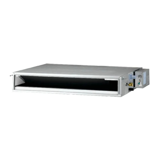
INTRODUCTION INTRODUCTION [Ceiling Concealed Duct] Air inlet vents Air outlet vents Remote Controller (Accessory) Installation Tool Washer for Clamp Insulation for (Other) Name Drain hose Clamp metal hanging bracket (Tie Wrap) fitting • Manual Quantity 1 EA 2 EA 8 EA 4 EA 1 SET for gas pipe... - Page 13 INTRODUCTION [Wall Mounted] Air filter Front grille Signal receiver Display On/Off button Air outlet Air deflector Plasmaster Ionizer (Vertical louver & Horizontal vane) * The feature can be changed according to type of model. NOTE • When mechanical connectors are reused indoors, sealing parts shall be renewed. Installation Tool Name Quantity...
- Page 14 INTRODUCTION [Ceiling Cassette] Anti-bacteria filter Air Intake Air Outlet Wired Remote Controller (Accessory) Installation Tool Washer for Clamp Insulation for (Other) Name Clamp metal Drain hose hanging bracket (Tie Wrap) fitting Quantity 1 EA 2 EA 8 EA 4 EA 1 SET •...
- Page 15 INTRODUCTION [Console] Air filter Signal receiver Operation lamp Air purifier lamp ON/OFF button Air outlet Air inlet Remote Controller Allergy filter (Accessory) Installation Tool Name Drain Hose Other Installation Plate Quantity - Remote Controller 1 EA 1 EA - Remote Controller Holder - Battery (AAA) - 2 EA - Allergy Filter - Fixing Screw for R.Controller...
- Page 16 INTRODUCTION [Ceiling suspended type] Right side cover Louver Air outlet vent Air filters (behind inlet grille) Remote Controller (Accessory) Air inlet vent (inlet grille) Left side cover Installation Tool Figure Name Figure Name Screw driver Multi-meter Electric drill Hexagonal wrench Measuring tape, Knife Ammeter Hole core drill...
-
Page 17: Installation Places
INSTALLATION PLACES INSTALLATION PLACES Select the best Location [Ceiling Concealed Duct] - The place shall easily bear a load exceeding four times the indoor unit’s weight. - The place shall be able to inspect the unit as the figure. - The place where the unit shall be leveled. - The place shall allow easy water drainage. - Page 18 INSTALLATION PLACES [Wall Mounted] - There should not be any heat or steam near the unit. - Select a place where there are no obstacles around of the unit. - Make sure that condensation drainage can be conveniently routed away. - Do not install near a doorway.
- Page 19 INSTALLATION PLACES 10 or more Ceiling Ceiling Ceiling Board Ceiling Board 500 or 500 or 500 or 500 or more more more more Unit : mm Unit : mm Floor Floor Floor Floor Chassis 3 300 TQ / TR / TP / TP-B 3 600 TN / TM / TM-A 4 200...
- Page 20 INSTALLATION PLACES [Console] - There should not be any heat or steam near the unit. - Select a place where there are no obstacles around of the unit. - Make sure that condensation drainage can be conveniently routed away. - Do not install near a doorway. - Ensure that the interval between a wall and the left (or right) of the unit is more than 300 mm.
- Page 21 INSTALLATION PLACES [Ceiling suspended type] - There should not be any heat source or steam near the unit. - There should not be any obstacles to prevent the air circulation. - A place where air circulation in the room will be good. - A place where drainage can be easily obtained.
- Page 22 INSTALLATION PLACES Minimum floor area (for R32) - The appliance shall be installed, operated and stored in a room with a floor area larger than the minimum area. - Use the graph of table to determine the minimum area. Amin (m Floor standing Wall mounted Ceiling mounted...
-
Page 23: The Indoor Unit Installation
THE INDOOR UNIT INSTALLATION THE INDOOR UNIT INSTALLATION Air conditioner Take enough distance Use the ventilation fan for smoke-collecting hood with sufficient capacity. Cooking table CAUTION NOTE • Avoid the following installation location. • This air-conditioner uses a drain pump. 1. -
Page 24: Position Of Suspension Bolt
THE INDOOR UNIT INSTALLATION Position of suspension Bolt [Ceiling Concealed Duct – Mid Static] - Apply a joint-canvas between the unit and duct to absorb unnecessary vibration. - Apply a filter Accessory at air return hole. [Ceiling Concealed Duct – Low Static] Drainage hole (Unit: mm) Dimension... - Page 25 THE INDOOR UNIT INSTALLATION - A place where the unit will be leveled and - Insert the set anchor and washer onto the that can support the weight of the unit. suspension bolts for locking the suspension bolts on the ceiling. - A place where the unit can withstand its vibration.
- Page 26 THE INDOOR UNIT INSTALLATION Front of view [Ceiling Cassette] - The unit must be horizontal or declined to the drain hose connected when finished Ceiling installation. Ceiling Level gauge Ceiling board Drain Pump use Drainage hole Ceiling Concealed Duct – Low static TP/TN/TM Series 875(Ceiling opening) 787(Hanging bolt)
- Page 27 THE INDOOR UNIT INSTALLATION Ceiling 4Way Keep the length of the bolt from the bracket to 40 mm Air Conditioner body Ceiling board Keep the length of 15~18 mm between the air conditioner Ceiling bottom surface and the ceiling board surface Set screw of Paper model...
-
Page 28: Fixing Installation Plate
THE INDOOR UNIT INSTALLATION Fixing Installation Plate Measure the wall and mark the centerline. It is also important to use caution concerning the location of the installation [Wall Mounted] plate. Routing of the wiring to power The wall you select should be strong and solid outlets is through the walls typically. -
Page 29: Connecting The Piping
THE INDOOR UNIT INSTALLATION Connecting the Piping Assembly of chassis cover Insert 4 hooks of the chassis cover into Pull the cover at the bottom of the indoor unit. Pull the cover ① → ②. gap of the chassis certainly. Remove the cover from the indoor unit. - Page 30 THE INDOOR UNIT INSTALLATION Good case NOTE - Press on the tubing cover and unfold the Installation Information. For right piping. tubing to downward slowly. And then bend Follow the instruction above. to the left side slowly. Installation of Indoor Unit Hook the indoor unit onto the upper portion of the installation plate.( engage the three hooks at the top of the indoor...
- Page 31 THE INDOOR UNIT INSTALLATION <Right side piping> Piping Insert the connecting cable through the bottom side of indoor unit and connect the cable (You can see detail contents in 'Connecting the cables' section) View <Left side piping> Slide up the metal plate cover Terminal block Connecting cable...
- Page 32 THE INDOOR UNIT INSTALLATION Finishing the indoor unit [Console] installation Preparation / Removing front panel Mount the tubing holder in the original Open the front grille by pulling forward position. Then pull out the link of grille from groove Ensure that the hooks are properly seated in front panel.
- Page 33 THE INDOOR UNIT INSTALLATION Preparation / For Moldings , Side Refrigerant Piping Piping, and Concealed Installation The location of hole is different depending on which side of the pipe is taken out. For Moldings Drill a hole (Ø 70 mm)in the point indicated Remove the slit portions on the Rear symbol in the illustration as below Panel.
- Page 34 THE INDOOR UNIT INSTALLATION The Outer diameter of Drain Hose (which is supplied with indoor unit) is 17 mm at connecting end, 600 mm long. Use commercial rigid PVC pipe for extension. Insulate the indoor drain pipe with 10 mm or more of insulation material to prevent condensation.
- Page 35 THE INDOOR UNIT INSTALLATION Half concealed installation. Make a wall hole of the size shown Fig-1. (Unit: mm) Wall Supplemental plate Supplemental plate (Field supply) (Field supply) Hole 1) Normal concealed 2) Deep concealed <Fig - 1> 2 Installation of supplemental plate for attaching main unit. •...
- Page 36 THE INDOOR UNIT INSTALLATION 4 Remove the Deco Covers and Fixing Indoor Unit 1) Remove the Deco Covers. 2) Insert the Indoor Unit to the Wall hole. 3) Secure using 6 screws. (shown in the illustration) NOTE Check the horizon of Indoor unit with the wall. Please use the Leveler on the drain pan guide. Leveler Drain pan Less than 5 mm...
- Page 37 THE INDOOR UNIT INSTALLATION Connecting the Piping When you connect the refrigerant pipe, it is easier that you connect the gas pipe first. Hold up the Sensor Link. Separate the Pipe Bracket (2 screws) Connect the refrigerant pipe. Assemble the Pipe Bracket (2 screws) Put down the Sensor Link After connecting, check the pipe arrangement as per illustration.
-
Page 38: Open Side-Cover
THE INDOOR UNIT INSTALLATION Open side-cover Step 4 [Ceiling suspended type] Step 1 - Knock out the pipe hole from the left sidecover with nipper/plier. - Remove two screws from side-cover. CAUTION Step 2 Hold the side-cover with other hand while tapping to prevent it to fall down. -
Page 39: Mounting The Anchor Nut And Bolt
THE INDOOR UNIT INSTALLATION Mounting the anchor nut and Anchor nut bolt Ceiling - Prepare 4 suspension bolts. (Each bolts length should be same.) Washer Washer Washer Suspension Suspension Suspension - Measure and mark the position for the bolts bolts bolts Suspension bolts and the piping hole. - Page 40 THE INDOOR UNIT INSTALLATION Front of view - The unit must be horizontal or inclined at angle. - The inclination should be less than or equal to 1° or in between 10 to 20 mm inclined in drain direction as shown in fig. Ceiling 10~20 mm Side of view...
-
Page 41: Indoor Unit Drain Piping
THE INDOOR UNIT INSTALLATION Indoor Unit Drain Piping [Type : Round] [Ceiling Concealed Duct / Cassette] 1/50~1/100 - Drain piping must have down-slope (1/50 to 1/100): be sure not to provide up-and-down Flexible hose Be sure to loop slope to prevent reversal flow. Unit : mm - During drain piping connection, be careful not to exert extra force on the drain port on... - Page 42 THE INDOOR UNIT INSTALLATION Drain test [Wall Mounted] The air conditioner uses a drain pump to To check the drainage drain water. Use the following procedure to test the Pour a glass of water on the evaporator. drain pump operation: Ensure the water flows through the drain - Connect the main drain pipe to the exterior hose of the indoor unit without any...
-
Page 43: Drain Test
THE INDOOR UNIT INSTALLATION [Ceiling suspended type] Do not make drain piping like the following. - Drain piping must have down-slope (1/50 to 1/100): be sure not to provide up - and - down slope to prevent reversal flow. - During drain piping connection, be careful Accumulated Do not raise drain water... - Page 44 THE INDOOR UNIT INSTALLATION HEAT INSULATION - Use the heat insulation material for the refrigerant piping which has an excellent heat-resistance (over 120 °C). - Precautions in high humidity circumstance: This air conditioner has been tested according to the "KS Standard Conditions with Mist" and confirmed that there is not any default.
-
Page 45: Wiring Connection
THE INDOOR UNIT INSTALLATION Wiring Connection Wiring Connection for Round Type - Connect the wires to the terminals on the * The feature can be changed according a control box individually according to the type of model. outdoor unit connection. * Pipes and wires should be purchased - Ensure that the color of the wires of outdoor separately for installation of the product. - Page 46 THE INDOOR UNIT INSTALLATION Connect the cable to the indoor unit by Terminal Block connecting the wires to the terminals on the control board individually according to the outdoor unit connection. (Ensure that the color of the wires of the outdoor unit and the terminal No.
- Page 47 THE INDOOR UNIT INSTALLATION CAUTION CAUTION • The connecting cable connected to the - The circuit diagram is a subject to indoor and outdoor unit should be change without notice. complied with the following - The earth wire should be longer than the specifications (Rubber insulation, type common wires.
- Page 48 THE INDOOR UNIT INSTALLATION Precautions when laying power - For wiring, use the designated power wire and connect firmly, then secure to prevent wiring outside pressure being exerted on the Use round pressure terminals for connections terminal block. to the power terminal block. - Use an appropriate screwdriver for tightening the terminal screws.
-
Page 49: Electrical Wiring
THE INDOOR UNIT INSTALLATION CAUTION Electrical Wiring All wiring must comply with LOCAL According to the confirmation of the above REGULATIONS. conditions, prepare the wiring as follows. Select a power source that is capable of Never fail to have an individual power supplying the current required by the air circuit specifically for the air conditioner. -
Page 50: Flaring Work
THE INDOOR UNIT INSTALLATION Flaring Work Putting nut on - Remove flare nuts attached to indoor and Main cause for gas leakage is due to defect of outdoor unit, then put them on pipe/tube flaring work. Carry out correct flaring work in having completed burr removal. - Page 51 THE INDOOR UNIT INSTALLATION CAUTION Connecting the installation pipe and drain hose to the indoor unit. • The installation of pipe-work shall be kept to a minimum Align the center of the pipes and sufficiently tighten the flare nut by hand •...
-
Page 52: Test Running
THE INDOOR UNIT INSTALLATION Test Running Wrap the insulation material around the connecting portion. - Check that all tubing and wiring are properly connected. Overlap the connection pipe insulation material and the indoor unit pipe insulation - Check that the gas and liquid side service material. - Page 53 THE INDOOR UNIT INSTALLATION Test operation Pump Down This is performed when the unit is relocated or the refrigerant circuit is serviced. Pump Down means collecting all refrigerant into the outdoor unit without the loss of refrigerant. NOTE Be sure to perform Pump Down procedure in the cooling mode.
-
Page 54: Heating Only Mode
THE INDOOR UNIT INSTALLATION Heating Only Mode * How to enter the installer mode Press Reset Button and ‘A’ Button ( Heating Only Mode switching function setup Supply the power to the unit with no functions active. Enter the Installer Code and set the code to 47. -
Page 55: Smart Diagnosis (Optional)
Diagnosis of operating information Enter the Installer Code and set the code to 57. Click the “Receive” button on the main SETUP screen of LG AC Smart Diagnosis App on Press your smart phone. Press and hold your smart phone close to the indoor unit. -
Page 56: Manual The Decor, Air Filter Assembly & Disassembly
THE INDOOR UNIT INSTALLATION Manual the decor, air filter Assembly & Disassembly Disassemble the decor Disassemble the air filter Turn off the power and unplug the power cord. Turn off the power and unplug the power cord. Pull the decor at the bottom of the indoor unit. Hold the knob of the air filter, Lift it up slightly. - Page 57 THE INDOOR UNIT INSTALLATION Precautions about installation in regions with extreme snowfall and cold temperatures To ensure the outdoor unit operates properly, certain measures are required in locations where there is a possibility of heavy snowfall or severe wind chill or cold : Prepare for severe winter wind chills and heavy snowfall, even in areas of the country where these are unusual phenomena.
-
Page 58: Installation Of Decorative Panel(Accessory)
INSTALLATION OF DECORATIVE PANEL(ACCESSORY) INSTALLATION OF DECORATIVE PANEL(ACCESSORY) Fit the panel on the unit by inserting hooks The decorative panel has its installation as shown in picture. direction. Before installing the decorative panel, always remove the paper template. Remove the packing and take out air inlet grille from front panel. - Page 59 INSTALLATION OF DECORATIVE PANEL(ACCESSORY) Fit the corner covers. Install the air inlet grille and Filter on the panel. - After inserting the edge of the grill into the panel body, close the door lock and press on the left, right, and center sections.
- Page 60 INSTALLATION OF DECORATIVE PANEL(ACCESSORY) CAUTION CHECK THE FOLLOWING ITEMS WHEN INSTALLATION IS COMPLETED - After completing work, be sure to measure and Install certainly the decorative panel. record trial run properties, and store measured Cool air leakage causes sweating. ⇨ Water drops fall. data, etc.
- Page 61 INSTALLATION OF DECORATIVE PANEL(ACCESSORY) Test operation Evaluation of the performance During the TEST OPERATION, the unit Operate the unit for 10~15 minutes, then operates in cooling mode at high speed fan, check the system refrigerant charge: regardless of room temperature and resets in Measure the pressure of the gas side 18 minutes.
-
Page 62: Installation Instructions
INSTALLATION INSTRUCTIONS INSTALLATION INSTRUCTIONS Installer Setting - How to enter installer setting mode CAUTION Installer setting mode is to set the detail function of the remote controller. If the installer setting mode is not set correctly, it can cause problems to the product, user injury or property damage. -
Page 63: Installer Setting - Installer Setting Code Table
INSTALLATION INSTRUCTIONS Installer Setting - Installer Setting Code Table Installer Setting Code Table Function Function code Setting value Remote controller LCD 0 : Set to master Mode override 1 : Set to slave 1 : Standard 2 : Low Ceiling height Selection 3 : High 4 : Super high... -
Page 64: Installer Setting - Setting Address Of Central Control
INSTALLATION INSTRUCTIONS Installer Setting - Setting Address of Central Control With the MODE button pressed, press the RESET button. By using the temperature setting button, set the indoor unit address. • Setting range : 00 ~ FF After setting the address, press the ON/OFF button toward the indoor unit 1 time. -
Page 65: Installer Setting - Static Pressure Step Setting
INSTALLATION INSTRUCTIONS Installer Setting - Static Pressure Step Setting This function is applied to only duct type. Setting this in other cases will cause malfunction. This function is only available on some products. This is the function that static pressure of the product is divided in 11 steps for setting. Ceiling Concealed Duct –... - Page 66 INSTALLATION INSTRUCTIONS Ceiling Concealed Duct – Mid static Table 2 Static Pressure [mmAq(Pa)] Capacity 2(20) 2.5(25) 3(29) 4(39) 6(59) 8(78) 10(98) 12(118) 13(127) 14(137) 15(147) Chassis Grade Step CMM (kBtu/h) Setting Value 32:01 32:02 32:03 32:04 32:05 32:06 32:07 32:08 32:09 32:10 32:11 Standard 14.5 Compact...
- Page 67 INSTALLATION INSTRUCTIONS Static Pressure [mmAq(Pa)] Capacity 4(39) 5(49) 6(59) 7(69) 8(78) 9(88) 10(98) 11(108) 12(118) 13(127) 15(147) Chassis Grade Step CMM (kBtu/h) Setting Value 32:01 32:02 32:03 32:04 32:05 32:06 32:07 32:08 32:09 32:10 32:11 Standard Compact HIGH Standard Compact HIGH High HIGH...
-
Page 68: Installer Setting - Auto Esp
INSTALLATION INSTRUCTIONS NOTE 1. Be sure to set the value referring table 2. Unexpected set value will cause mal-function. 2. Table 2 is based at 230 V. According to the fluctuation of voltage, air flow rate varies. 3. Factory Set(External Static Pressure) each Model Capacity Factory set (E.S.P.) mmAq(Pa) (kBtu/h) -
Page 69: Dip Switch Setting
DIP SWITCH SETTING DIP SWITCH SETTING Indoor PCB Indoor PCB Indoor PCB Function Description Setting Off Setting On Default Selection of Master Group Control Master Slave or Slave Wired/Wireless remote Dry Contact Selection of Dry controller Auto Mode Contact Mode Selection of Manual or Auto operation Mode Fan continuous...