Table of Contents
Advertisement
INSTALLATION MANUAL
AIR
CONDITIONER
Please read this installation manual completely before installing the product.
Installation work must be performed in accordance with the national wiring
standards by authorized personnel only.
Please retain this installation manual for future reference after reading it
thoroughly.
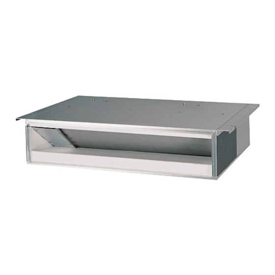
4-WAY CEILING CASSETTE
MFL61971250
Rev.00_060818
Copyright © 2018 LG Electronics Inc. All Rights Reserved.
www.lghvac.com
www.lg.com
Advertisement
Table of Contents

Related Manuals for LG LDN097HV4


Summary of Contents for LG LDN097HV4
- Page 1 Installation work must be performed in accordance with the national wiring standards by authorized personnel only. Please retain this installation manual for future reference after reading it thoroughly. 4-WAY CEILING CASSETTE www.lghvac.com www.lg.com MFL61971250 Rev.00_060818 Copyright © 2018 LG Electronics Inc. All Rights Reserved.
- Page 2 TIPS FOR SAVING ENERGY TIPS FOR SAVING ENERGY Here are some tips that will help you minimize the power consumption when you use the air conditioner. You can use your air conditioner more efficiently by referring to the instructions below: •...
- Page 3 IMPORTANT SAFETY INSTRUCTIONS IMPORTANT SAFETY INSTRUCTIONS READ ALL INSTRUCTIONS BEFORE USING THE APPLIANCE. Always comply with the following precautions to avoid dangerous situations and ensure peak performance of your product WARNING It can result in serious injury or death when the directions are ignored CAUTION It can result in minor injury or product damage when the directions are ignored WARNING...
- Page 4 IMPORTANT SAFETY INSTRUCTIONS Operation • Do not share the outlet with other appliances. - It will cause an electric shock or a fire due to heat generation. • Do not use the damaged power cord. - Otherwise, it may cause a fire or electrical shock. •...
- Page 5 IMPORTANT SAFETY INSTRUCTIONS CAUTION Installation • Install the drain hose to ensure that drain can be securely done. - Otherwise, it may cause water leakage. • Install the product so that the noise or hot wind from the outdoor unit may not cause any damage to the neighbors.
-
Page 6: Table Of Contents
TABLE OF CONTENTS TABLE OF CONTENTS INSTALLATION PLACES THE INDOOR UNIT INSTALLATION Indoor Unit Drain Piping Wiring Connection Flaring work Connection of piping INSTALLATION OF DECORATIVE PANEL(ACCESSORY) TEST RUNNING INSTALLATION INSTRUCTIONS Installer Setting - How to enter installer setting mode Installer Setting - Installer Setting Code Table Installer Setting - Setting Address of Central Control Installer Setting - Checking Address of Central Control... -
Page 7: Installation Places
INSTALLATION PLACES INSTALLATION PLACES - There should not be any heat source or steam near the unit. - There should not be any obstacles to prevent the air circulation. - A place where air circulation in the room will be good. - A place where drainage can be easily obtained. -
Page 8: The Indoor Unit Installation
THE INDOOR UNIT INSTALLATION THE INDOOR UNIT INSTALLATION Ceiling Level gauge Ceiling board Included Paper Cardboard on the bottom of packaging CAUTION TM/TN/TP Chassis 875(34-7/16) (Ceiling opening) • This air-conditioner uses a drain pump. 787(30-15/16) • Install the unit horizontally using a level (Hanging bolt) bolt) gauge. -
Page 9: Indoor Unit Drain Piping
THE INDOOR UNIT INSTALLATION Avoid installng air conditioner in such Wall places where cooking oil or iron powder is Indoor Outdoor generated. Avoid places where inflammable gas is generated. Avoid place where noxious gas is generated. Avoid places near high frequency generators. Hanging bolt (W3/8 or M10) Flat washer with insulation... -
Page 10: Wiring Connection
THE INDOOR UNIT INSTALLATION HEAT INSULATION 300(11.8) or less - Use the heat insulation material for the 1,000(39.4)~ 1,500(59.1) refrigerant piping which has an excellent heat- resistance (over 120°C). - Precautions in high humidity circumstance: This air conditioner has been tested according Drain raising pipe to the "KS Standard Conditions with Mist"... - Page 11 THE INDOOR UNIT INSTALLATION Precautions when laying power and ground wiring Use round pressure terminals for connections to the power terminal block. When laying ground wiring, you must use Lock nut round pressure terminals. Conduit Conduit Round pressure terminal mounting plate Power wire CAUTION...
-
Page 12: Flaring Work
THE INDOOR UNIT INSTALLATION Flaring work Flaring work - Carry out flaring work using flaring tool as Main cause of gas leakage is defect in flaring shown below. work. Carry out correct flaring work in the following procedure. A Inch (mm) Pipe diameter Thickness Inch (mm) -
Page 13: Connection Of Piping
THE INDOOR UNIT INSTALLATION Connection of piping For Single zone Align the center of the piping and sufficiently tighten the flare nut by hand. Refrigerant Connections ODU Capacity Pipe size (kBtu/h) Liquid Liquid Single 3/8 (Ø9.52) 5/8 (Ø15.88) Zone h Indoor Unit (18k) includes the sockets. (Ø... -
Page 14: Installation Of Decorative Panel(Accessory)
INSTALLATION OF DECORATIVE PANEL(ACCESSORY) INSTALLATION OF DECORATIVE PANEL(ACCESSORY) Insert two screws on diagonal corners of The decorative panel has its installation panel. Do not tighten the bolts completely. direction. (The fixing screws are included in the Before installing the decorative panel, indoor unit box.) always remove the paper template. - Page 15 Link INSTALLATION OF DECORATIVE PANEL(ACCESSORY) Filter guide Connect one display connector and two Install the air inlet grille and Filter on the vane control connectors of front panel to panel. indoor unit PCB. The position marking on PCB is as: Display connector : CN-DISPLAY Vane control connector: CN-VANE 1,2 CN-DISPLAY...
-
Page 16: Test Running
TEST RUNNING TEST RUNNING PRECAUTIONS IN TEST RUN Connection of power supply - The initial power supply must provide at least - Connect the power supply cord to the 90% of the rated voltage. independent power supply. Otherwise, the air conditioner should not be Circuit breaker is required. -
Page 17: Installation Instructions
INSTALLATION INSTRUCTIONS INSTALLATION INSTRUCTIONS Installer Setting - How to enter installer setting mode CAUTION Installer setting mode is to set the detail function of the remote controller. If the installer setting mode is not set correctly, it can cause problems to the product, user injury or property damage. -
Page 18: Installer Setting - Installer Setting Code Table
INSTALLATION INSTRUCTIONS Installer Setting - Installer Setting Code Table Function Function Code Setting Value Remote Controller LCD 0 : Set to Master Mode Override 1 : Set to Slave 1 : Standard 2 : Low Ceiling Height Selection 3 : High 4 : Super High 0 : Set to Master Group Control... -
Page 19: Installer Setting - Setting Address Of Central Control
INSTALLATION INSTRUCTIONS Installer Setting - Setting Address of Central Control With the MODE button pressed, press the RESET button. By using the temperature setting button, set the indoor unit address. - Setting range : 00 ~ FF After setting the address, press the ON/OFF button toward the indoor unit 1 time. - Page 21 Please call the installing contractor of your product, as warranty service will be provided by them. Service call Number # : (888) LG Canada, (888) 542-2623 CANADA Numéro pour les appels de service : LG Canada, 1-888-542-2623...