Table of Contents
Advertisement
Quick Links
Advertisement
Table of Contents

Related Manuals for Datavideo VS-150

Summary of Contents for Datavideo VS-150
- Page 1 SAMPLING VECTOR SCOPE VS-150 Instruction Manual...
-
Page 2: Table Of Contents
Disclaimer of Product and Services The information offered in this instruction manual is intended as a guide only. At all times, Datavideo Technologies will try to give correct, complete and suitable information. However, Datavideo Technologies cannot exclude that some information in this manual, from time to time, may not be correct or may be incomplete. -
Page 3: Fcc Compliance Statement
7. This product should only be operated from the type of power source indicated on the marking label of the AC adapter. If you are not sure of the type of power available, consult your Datavideo dealer or your local power company. -
Page 4: Warranty
Card, USB Thumb Drive, Lighting, Camera module, PCIe Card are covered for 1 year. • The three-year warranty must be registered on Datavideo's official website or with your local Datavideo office or one of its authorized distributors within 30 days of purchase. -
Page 5: Disposal
Waste Electrical and Electronic Equipment. For more detailed information about the recycling of this product, please contact your local Datavideo office. CE Marking is the symbol as shown on the left of this page. The letters "CE" are the abbreviation of French phrase "Conformité... -
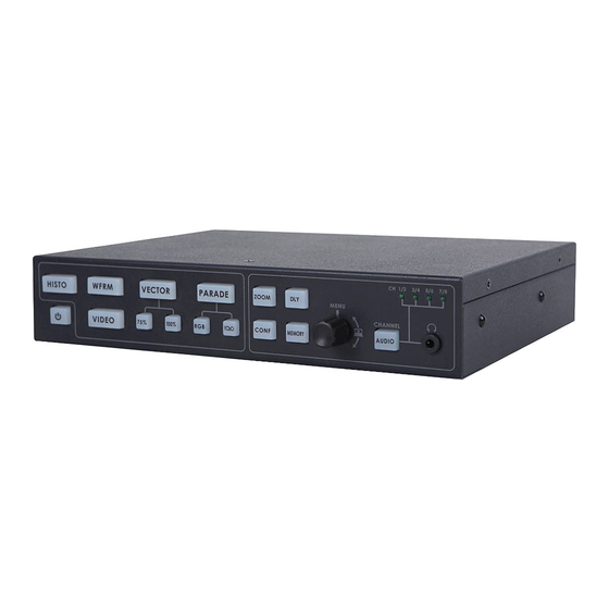
Page 6: Connections & Controls
Switches the power On / Off. HISTOGRAM HISTOGRAM is used to detect the overall brightness of a location. Through VS-150 to detect light sources from all directions reading by the camera, one can individually adjust each camera to the desired state. - Page 7 SDI LOOPTHROUGH Set loop through on / off mode CAPTURE Set sampling mode FRAME: Capture the entire frame as a sample. FIELD1: Capture FIELD 1 as a sample only. FIELD2: Capture FIELD 2 as a sample only. FIRMWARE REVISION Display current software version X DELA This is used by adjusting the position of the matrix.
- Page 8 REMOTE: When switched to REMOTE, the front panel controls are active on the VS-150. LOCAL: When switched to LOCAL, the USB port can be connected to a laptop in order to update the firmware. Mini USB USB interface for firmware update HD/SD-SDI INPUT BNC connector for SDI input.
-
Page 9: Vs-150 Output Display
VS-150 Output Display... -
Page 10: Menu Control And Options
Menu Control and Options The VS-150 is a menu driven unit. The menu is viewed as part of the output display when it has been connected to a HDMI / SDI monitor. The menu options are scrolled by turning the Menu Dial to the left or right (See item 1 on page 8). A pointer ( ►) to the left of the menu options indicates which item is currently selected. - Page 11 Audio embedded into the SDI / HD-SDI signal can be monitored by plugging headphones into the 3.5mm jack socket on the VS-150 front panel. Using the AUDIO VOLUME option, the Menu Dial can be used to increase or reduce the volume at the connected headphones, so it is monitored at a comfortable level.
-
Page 12: Vs-150 Quick Start Guide
6. Once the first camera is correctly calibrated select TOOLS> TRACE MEMORY> SAVE TRACE to save the calibrated matrix levels from the first camera. 7. Now connect VS-150 to the second camera on the set. Adjust the white and black balance on the next camera as described earlier. - Page 13 5. Once the first camera is correctly calibrated select TOOLS> TRACE MEMORY> SAVE TRACE to save the calibrated matrix levels from the first camera. 6. Now connect VS-150 to the second camera on the set. Adjust the white and black balance on the next camera as described earlier.
- Page 14 1. Under the same on set lighting conditions aim the camera at a colour reference chart (such as DSC labs’ Chroma Du Monde). 2. Select VECTORSCOPE mode on the VS-150 using the NEXT MODE option. 3. Now, the VECTORSCOPE displays the analyzed colour components. If the white balance of one camera had been altered, the VECTORSCOPE matrix can be used as a check point to ensure all cameras have been correctly aligned.
-
Page 15: Vs-150 Advanced Application
VS-150 Advanced Application RGB PARADE and White Balance Adjustment i. Select PARADE mode on the VS-150 using the NEXT MODE option. Then point the camera at the white background or white reference card. ii. When the white balance is correctly adjusted, The RGB traces should be flat, balanced, and parallel to one another in a straight line. -
Page 16: Supported Sdi / Hd-Sdi Input Video Formats
Select VECTORSCOPE mode on the VS-150 using the NEXT MODE option. iii. The VECTORSCOPE matrix displaying on VS-150 represents the colour components from the camera. iv. Use the SAVE TRACE feature under TOOLS to compare the colour components between cameras. -
Page 17: Application Diagram
Application Diagram... -
Page 18: Specifications
Specifications 1x SDI/HD-SDI input (HD-SDI SMPTE 292M 1.5Gbps, Interface SD-SDI SMPTE 259M-C 270Mbps with Embedded Audio) 1x SDI/HD-SDI Loop through output 1x HDMI Output SMPTE 259M-C (270Mbps - 525/625 Component Video) and SMPTE 292M (1.485/1.001 Gbps) Connector BNC (IEC 169-8) Impedance 75 Ω Return Loss HD >... -
Page 19: Note
NOTE... -
Page 20: Service And Support
Service & Support It is our goal to make owning and using Datavideo products a satisfying experience. Our support staff is available to assist you to set up and operate your system. Contact your local office for specific support requests. Plus, DATAVIDEO WORLDWIDE OFFICES please visit www.datavideo.com to access our FAQ section.