Asus PN Series User Manual
Hide thumbs
Also See for PN Series:
- User manual (46 pages) ,
- User manual (112 pages) ,
- User manual (46 pages)

Related Manuals for Asus PN Series


Summary of Contents for Asus PN Series
- Page 1 Questo manuale d’istruzione è fornito da trovaprezzi.it. Scopri tutte le offerte per Asus PN40 BC519MC o cerca il tuo prodotto tra le migliori offerte di PC Desktop e Workstation Mini PC PN Series User Manual...
- Page 2 Copyright © 2018 ASUSTeK COMPUTER INC. All Rights Reserved. LIMITATION OF LIABILITY Circumstances may arise where because of a default on ASUS’ part or other liability, you are entitled to recover damages from ASUS. In each such instance, regardless of the basis on which you are entitled to claim damages from ASUS, ASUS is liable for no more than damages for bodily injury (including death) and damage to real property and tangible personal property;...
-
Page 3: Table Of Contents
Load default BIOS settings ....................28 Upgrading your Mini PC Removing the bottom cover .....................30 Replacing the bottom cover ....................31 Installing memory modules ....................32 Installing 2.5” HDD or SSD ....................33 Installing the M.2 SSD (on selected models) ......................34 Installing the wireless card ....................35 PN Series... - Page 4 Appendix Safety information .........................38 Setting up your system .......................38 Care during use ........................38 Regulatory notices ........................40 ASUS contact information ....................45 PN Series...
-
Page 5: About This Manual
This chapter provides you with information on how to upgrade the memory modules, wireless modules, and hard disk drive / solid state drive of your Mini PC. Appendix This section includes notices and safety statements your Mini PC. PN Series... -
Page 6: Conventions Used In This Manual
Mini PC's data and components. Typography Bold text Indicates a menu or an item to select. Italic This indicates sections that you can refer to in this manual. PN Series... -
Page 7: Package Contents
Package contents Your Mini PC package contains the following items: ASUS Mini PC PN Series AC power adapter* Power cord* Technical documentations PN Series... - Page 8 For details on these accessories, refer to their respective user manuals. • T he device illustration is for reference only. Actual product specifications may vary with models. • I f the device or its components fail or malfunction during normal and proper use within the warranty period, bring the warranty card to the ASUS Service Center for replacement of the defective components. PN Series...
-
Page 9: Getting To Know Your Mini Pc
Getting to know your Mini... -
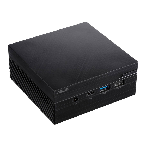
Page 10: Features
(4) seconds to force shutdown your Mini PC. Headphone/Headset/Microphone jack This port allows you to connect amplified speakers or headphones. You can also use this port to connect your headset or an external microphone. PN Series... - Page 11 This port also supports the Battery Charging 1.2 technology that allows you to charge your USB devices. NOTE: Battery Charging 1.2 technology is only available on selected models. Drive activity indicator This indicator lights up when your Mini PC is accessing the internal storage drive. PN Series...
-
Page 12: Left View
Left view Air vents (intake vent) The air vents allow cooler air to enter your Mini PC chassis. IMPORTANT: For an optimum heat dissipation and air ventilation, ensure that the air vents are free from obstructions. PN Series... -
Page 13: Right View
The air vents allow cooler air to enter your Mini PC chassis. IMPORTANT: For an optimum heat dissipation and air ventilation, ensure that the air vents are free from obstructions. Kensington security slot The Kensington security slot allows you to secure your Mini PC using Kensington® security products. PN Series... -
Page 14: Rear View
Rear view PN40 PN60 HDMI port The HDMI (High Definition Multimedia Interface) port supports a Full-HD device such as an LCD TV or monitor to allow viewing on a larger external display. PN Series... - Page 15 The HDMI (High Definition Multimedia Interface) port supports a Full-HD device such as an LCD TV or monitor to allow viewing on a larger external display. DisplayPort (on selected models) This port allows you to connect your Mini PC to an external display. PN Series...
- Page 16 The 8-pin RJ-45 LAN port supports a standard Ethernet cable for connection to a local network. USB 3.1 Gen 1 port The USB 3.1 Gen 1 (Universal Serial Bus) port provides a transfer rate up to 5 Gbit/s. PN Series...
- Page 17 Mini PC. To prevent damage to the Mini PC, always use the supplied power adapter. WARNING! The power adapter may become warm to hot when in use. Do not cover the adapter and keep it away from your body. PN Series...
- Page 18 PN Series...
-
Page 19: Using Your Mini Pc
Using your Mini PC... -
Page 20: Getting Started
Connect the power cord to the AC power adapter. Connect the DC power connector into your Mini PC’s power (DC) input. Plug the AC power adapter into a 100V~240V power source. NOTE: The power adapter may vary in appearance, depending on models and your region. PN Series... - Page 21 Mini PC. • T he socket outlet must be easily accessible and near your Mini • T o disconnect your Mini PC from its main power supply, unplug your Mini PC from the power socket. NOTE: The power adapter may vary between models and territories, please refer to the following for more information on the different adapters: 65W Power adapter • Input voltage: 100-240 Vac • Input frequency: 50-60 Hz • Rating output current: 3.42 A (65 W) • Rating output voltage: 19 V PN Series...
-
Page 22: Connect A Display Panel To Your Mini Pc
When switching between display ports, please ensure to remove the cable of the other port. • F or PN60 Series, up to two display ports may be connected simultaneously. Ensure your device is powered off when switching between the USB 3.1 Gen 1 Type-C™/DisplayPort combo port and VGA/HDMI port*. This port may vary per model PN Series... - Page 23 Connect one end of an HDMI, VGA, Mini DisplayPort, or a DisplayPort cable to an external display, and the other end of the cable to your Mini PC’s HDMI port, VGA port, Mini DisplayPort, or a DisplayPort. Connect display via VGA port Connect display via HDMI port PN Series...
- Page 24 Connect display via DisplayPort Connect display via Mini DisplayPort PN Series...
-
Page 25: Connect The Usb Cable From Keyboard Or Mouse
You can also connect a USB dongle for a wireless keyboard and mouse set. To connect a keyboard and mouse to your Mini PC: Connect the USB cable from your keyboard and mouse to any of the USB ports of your Mini PC. NOTE: The keyboard varies with country or region. PN Series... -
Page 26: Turn On Your Mini Pc
Turn on your Mini PC Press the power button to turn on your Mini PC. PN Series... -
Page 27: Turning Your Mini Pc Off
• An error message appears on the screen during the system bootup and requests you to run the BIOS Setup. • You have installed a new system component that requires further BIOS settings or update. WARNING! Inappropriate BIOS settings may result to instability or boot failure. We strongly recommend that you change the BIOS settings only with the help of a trained service personnel. PN Series... -
Page 28: Load Default Bios Settings
NOTE: POST (Power-On Self Test) is a series of software controlled diagnostic tests that run when you turn on your Mini PC. • Navigate to the Exit menu. Select the Load Optimized Defaults option, or you may press <F5>. • • Select OK to load the default BIOS values. PN Series... -
Page 29: Upgrading Your Mini Pc
Upgrading your Mini PC... -
Page 30: Removing The Bottom Cover
IMPORTANT! • I t is recommended that you install or upgrade the memory modules, wireless card, and solid state drive (SSD), under professional supervision. Visit an ASUS service center for further assistance. • E nsure that your hands are dry before proceeding with the rest of the installation process. Before installing any of the features in this guide, use a grounded wrist strap or touch a safely grounded object or metal object to avoid damaging them due to static electricity. -
Page 31: Replacing The Bottom Cover
(B). Replacing the bottom cover Push the bottom cover from the left side towards the right side of the Mini PC (A), then secure it using the four (4) screws removed previously (B). PN Series... -
Page 32: Installing Memory Modules
Maximum 32GB memory. PN40: Maximum 8GB memory. IMPORTANT! Refer to http://www.asus.com for the list of compatible DIMMs. You can only install DDR4 SO-DIMMs to the Mini PC’s DIMM slots. Align and insert the memory module into the slot (A) and press it down (B) until it is securely seated in place. -
Page 33: Installing 2.5" Hdd Or Ssd
Prepare your 2.5” HDD or SSD, then align it with the storage bay on the bottom cover of your Mini PC. Insert your HDD or SSD into the storage bay (A), then secure it with four (4) screws (B). IMPORTANT! This device only supports 7mm and 9.5mm 2.5” HDD or SSD. PN Series... -
Page 34: Installing The M.2 Ssd (On Selected Models)
Align and insert the 2280 M.2 SSD into its slot inside the Mini PC. Gently push down the 2280 M.2 SSD on top of the screw hole and fasten it using one of the bundled 3mm round screws. PN Series... -
Page 35: Installing The Wireless Card
Installing the wireless card NOTE: Your Mini PC includes a M.2 slot for 2230 wireless and Bluetooth modules. Refer to http://www.asus.com for the list of compatible wireless and Bluetooth modules. (optional) Remove the M.2 SSD if an M.2 SSD is installed. To remove the M.2 SSD, remove the screw from the screw hole, then remove the... - Page 36 NOTE: • C onnecting antennas to your wireless card may strengthen the wireless signal. • A soft clicking sound indicates that the antenna has been securely attached on the wireless card. PN Series...
-
Page 37: Appendix
Appendix... -
Page 38: Safety Information
• This equipment should be installed and operated with a minimum distance of 20cm between the radiator and your body. Care during use • Do not walk on the power cord or allow anything to rest on it. • Do not spill water or any other liquids on your system. • When the system is turned off, a small amount of electrical current still flows. Always unplug the power cord from the power outlets before cleaning the system. PN Series... - Page 39 This symbol of the crossed out wheeled bin indicates that the product (electrical, electronic equipment, and mercury-containing button cell battery) should not be placed in municipal waste. Check local technical support services for product recycling. PN Series...
-
Page 40: Regulatory Notices
ASUS REACH website at http://csr.asus.com/ english/REACH.htm ASUS Recycling/Takeback Services ASUS recycling and takeback programs come from our commitment to the highest standards for protecting our environment. We believe in providing solutions for you to be able to responsibly recycle our products, batteries, other components, as well as the packaging materials. - Page 41 IMPORTANT! Outdoor operations in the 5.15~5.25 GHz band is prohibited. This device has no Ad-hoc capability for 5250~5350 and 5470~5725 MHz. CAUTION! Any changes or modifications not expressly approved by the grantee of this device could void the user’s authority to operate the equipment. PN Series...
- Page 42 Le présent appareil est conforme aux CNR d’Innovation, Sciences et Développement économique Canada applicables aux appareils radio exempts de licence. L’exploitation est autorisée aux deux conditions suivantes : (1) l’appareil ne doit pas produire de brouillage, et (2) l’utilisateur de l’appareil doit accepter tout brouillage radioélectrique subi, même si le brouillage est susceptible d’en compromettre le fonctionnement. CAN ICES-3(B)/NMB-3(B) PN Series...
- Page 43 2.412-2.484 GHz Ch01 through Ch14 Europe ETSI 2.412-2.472 GHz Ch01 through Ch13 Regional notice for Singapore Complies with This ASUS product complies with IMDA Standards. IMDA Standards DB103778 Regional notice for California WARNING Cancer and Reproductive Harm - www.P65Warnings.ca.gov Regional notice for Malaysia...
- Page 44 Agency and the U.S. Department of Energy helping us all save money and protect the environment through energy efficient products and practices. All ASUS products with the ENERGY STAR logo comply with the ENERGY STAR standard, and the power management feature is enabled by default.
-
Page 45: Asus Contact Information
+1-510-608-4555 Web site http://www.asus.com/us/ Technical Support Support fax +1-812-284-0883 Telephone +1-812-282-2787 Online support https://www.asus.com/support/Product/ ContactUs/Services/questionform/?lang=en-us ASUS COMPUTER GmbH (Germany and Austria) Address Harkort Str. 21-23, 40880 Ratingen, Germany +49-2102-959931 Web site http://www.asus.com/de Online contact http://eu-rma.asus.com/sales Technical Support Telephone +49-2102-5789555 Support Fax... - Page 46 PN Series...