
Related Manuals for Abit NI8 SLI Series


Summary of Contents for Abit NI8 SLI Series
- Page 1 NI8 SLI Series Intel Pentium 4 System Board Socket 775 User’s Manual 4200-0460-05 Rev. 1.02...
- Page 2 No part of this manual may be reproduced, transmitted or transcribed without the expressed written permission of the manufacturer and authors of this manual. If you do not properly set the motherboard settings, causing the motherboard to malfunction or fail, we cannot guarantee any responsibility. NI8 SLI Series...
-
Page 3: Table Of Contents
Features & Specifications ...1-1 1-2. Layout Diagram ...1-3 Chapter 2. Hardware Setup... 2-1 2-1. Install The Motherboard...2-1 2-2. Install CPU, Heatsink and Fan Assembly ...2-2 2-3. Install System Memory ...2-4 2-4. Install two Graphics Cards with NVIDIA SLI Technology ...2-6 2-5. - Page 4 Generate NVRaid Floppy Disk (32 bit/64 bit) ...G-1 Appendix H. Generate SIL3132Raid Floppy Disk (32 bit/64 bit) (NI8-SLI) ...H-1 Appendix I. POST Code Definition ... I-1 Appendix J. Troubleshooting (Need Assistance?) ...J-1 Appendix K. How to Get Technical Support ... K-1 NI8 SLI Series...
-
Page 5: Chapter 1. Introduction
Supports SATA AHCI, providing native command queuing and native hot plug • Supports SATA RAID 0/1/0+1 7. 2 SATA RAID (For model NI8 SLI only) • Serial ATA 3Gb/s by Sil 3132 PCIE controller • Supports SATA RAID 0/1 NCQ 8. - Page 6 • 1x Floppy port supports up to 2.88MB • 2x Ultra DMA 133/100/66/33 connectors • 4x SATA connectors • 2x SATA connectors (For model NI8 SLI only) • 3x USB headers 12. Back Panel I/O • ABIT Silent-OTES • 1x PS/2 keyboard, 1x PS/2 mouse •...
-
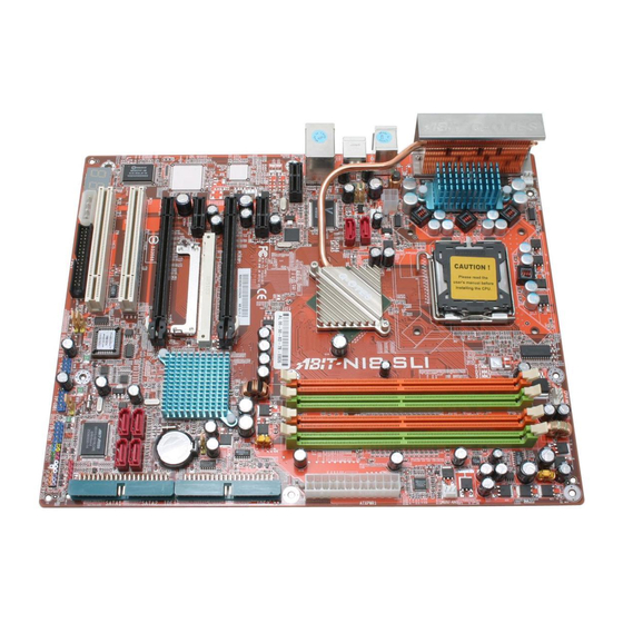
Page 7: Layout Diagram
Introduction 1-2. Layout Diagram User’s Manual... - Page 8 Chapter 1 NI8 SLI Series...
-
Page 9: Chapter 2. Hardware Setup
2-1. Install The Motherboard Most computer chassis have a base with many mounting holes to allow the motherboard to be securely attached, and at the same time, prevent the system from short circuits. There are two ways to attach the motherboard to the chassis base: 1. -
Page 10: Install Cpu, Heatsink And Fan Assembly
2. Rotate the lever to fully open position. 3. Use your right thumb on the bottom-right side of the load plate and lift it up to fully open position. NI8 SLI Series ® NOTE: Intel 2.8G Dual Core CPU is not supported by NVIDIA nForce4 SLI Intel Edition processors. - Page 11 9. Place the heatsink and fan assembly onto the socket. Align the four fasteners toward the four mounting holes on the motherboard. For detailed information on how to install your heatsink and fan assembly, please refer to the...
-
Page 12: Install System Memory
2-3. Install System Memory This motherboard provides four 240-pin DIMM slots for Single/Dual Channel DDR2 667 memory modules with memory expansion size up to 8GB. • To reach the optimum performance in dual-channel configurations, install identical DDR2 DIMM pairs for each channel. - Page 13 • [Dual Channel Asymmetric]: both channels are populated, but each channel has a different amount of total memory. (Channel A≠Channel B) Method DIMM1 512MB 512MB 256MB 256MB 256MB 256MB 256MB • [Dual Channel Symmetric]: both channels are populated where each channel has the same amount of total memory.
-
Page 14: Install Two Graphics Cards With Nvidia Sli Technology
NOTE: When PCIEXP2 slot functions as a PCIE x1 slot under Normal mode, insert the PCIE x1 card into the marked area of PCIEXP2 slot. This motherboard is factory pre-installed with an ABIT SLI switchboard. By the default “Normal” mode, this motherboard is set for one single graphics card operation. To operate two graphics cards on this motherboard, you will have to set the switchboard to “SLI”... - Page 15 Make sure the switchboard is completely inserted into the slot. 4. Insert the two graphics cards into PCIEXP1 and PCIEXP2 slots on the motherboard. 5. There are goldfingers on your SLI Graphics Cards reserved for the SLI Bridge Connector. User’s Manual...
- Page 16 7. The SLI bracket included in the package is used for supporting the SLI bridge connector and the two SLI graphics cards. NI8 SLI Series 8. Insert the SLI bracket into the bracket slot between the graphics cards. Secure the SLI bracket and the graphics cards to the chassis with screws.
-
Page 17: Connectors, Headers And Switches
WARNING: Always power off the computer and unplug the AC power cord before adding or removing any peripheral or component. Failing to so may cause severe damage to your motherboard and/or peripherals. Plug in the AC power cord only after you have carefully checked everything. -
Page 18: Fan Power Connectors
NBFAN1: Chipset Fan Power Connector • SYSFAN1: System Fan Power Connector • AUXFAN1: Auxiliary Fan Power Connector • OTESFAN1~2: OTES Fan Power Connector WARNING: These fan connectors are not jumpers. DO NOT place jumper caps on these connectors. NI8 SLI Series... -
Page 19: Cmos Memory Clearing Header
WARNING: Turn the power off first (including the +5V standby power) before clearing the CMOS memory. Failing to do so may cause your system to work abnormally or malfunction. (4). GURU Clock Connection Header This header is reserved for connecting ABIT’s exclusive GURU Clock. User’s Manual... -
Page 20: Wake-Up Header
Pin 1-2 shorted (default): Disable wake-up function support at USB port. Pin 2-3 shorted: Enable wake-up function support at USB port • USB-PWR5: Pin 1-2 shorted (default): Disable wake-up function support at USB port. Pin 2-3 shorted: Enable wake-up function support at USB port NI8 SLI Series... -
Page 21: Audiomax Slot
(6). AudioMAX Slot The slot “AUDIOMAX1” provides the audio input/output connection at back panel through an audio daughter-card. NOTE: Install this daughter-card at slot “AUDIOMAX1”. • S/PDIF Out: This connector provides an S/PDIF-Out connection through optical fiber to digital multimedia devices. •... - Page 22 S/PDIF Connection: Along with the motherboard package you can find an audio daughter-card for S/PDIF connection. • S/PDIF Input Connection: 1. Plug the end with 3.5mm adapter into the [Line-In] jack on this daughter-card. (This jack is used for either optical or line input.) 2.
-
Page 23: Front Panel Audio Connection Header
(7). Front Panel Audio Connection Header This header provides the connection to audio connector at front panel. (8). Internal Audio Connector This connector connects to the audio output of internal CD-ROM drive or add-on card. Pin Assignment Audio Mic. Audio Mic. Bias Speaker Out Right Channel Speaker Out Left... -
Page 24: Front Panel Switches & Indicators Headers
Connects to the Suspend LED cable (if there is one) of chassis front panel. • PWR (Pin 6, 8): Connects to the Power Switch cable of chassis front panel. • PLED (Pin 16, 18, 20): Connects to the Power LED cable of chassis front panel. NI8 SLI Series... -
Page 25: Additional Usb Port Headers
(10). Additional USB Port Headers These headers each provide 3 additional USB 2.0 ports connection through an USB cable designed for USB 2.0 specifications. (11). Status Indicator • LED11 (5VSB): This LED lights up when the power supply is connected with power source. 2 4 6 8 10 1 3 5 7 FP-USB1... -
Page 26: Floppy And Ide Disk Drive Connectors
NOTE: Make sure to configure the “Master” and “Slave” relation before connecting two drives by one single ribbon cable. The red line on the ribbon cable must be aligned with pin-1 on both the IDE port and the hard-drive connector. NI8 SLI Series... -
Page 27: Post Code Display
POST Code in address 80h to find out where the problem lies. This LED device also displays the “POST” Code of AC2005, an “uGuru” chipset developed exclusively by ABIT computer. NOTE: The decimal point lights up when executing the AC2005 POST action. -
Page 28: Serial Ata Connectors
This motherboard provides RAID 0, RAID 1 and RAID 0+1 configuration for Serial ATA hard drives through the NVIDIA MCP-04 chipset. For model NI8 SLI, SATA5 and SATA6 provide through the Silicon Image 3132 SATA chipset, you may configure a disk array by the Sil3132 SATA/RAID Driver option ROM utility. -
Page 29: Pci Express X1 Slots
(16). PCI Express x1 Slots These slots are used to attach the next generation of I/O architecture. (17). SLI Switchboard Slot This slot and the pre-installed ABIT SLI Switch set the graphic mode to either Normal or SLI mode. User’s Manual... -
Page 30: Back Panel Connectors
(18). Back Panel Connectors NI8 SLI: NI8 SLI GR: • Mouse: Connects to PS/2 mouse. • Keyboard: Connects to PS/2 keyboard. • LAN1: Connects to Local Area Network • USB1/USB2: Connects to USB devices such as scanner, digital speakers, monitor, mouse, keyboard, hub, digital camera, joystick etc. -
Page 31: Chapter 3. Bios Setup
Chapter 3. BIOS Setup This motherboard provides a programmable EEPROM that you can update the BIOS utility. The BIOS (Basic Input/Output System) is a program that deals with the basic level of communication between processor and peripherals. Use the BIOS Setup program only when installing motherboard, reconfiguring system, or prompted to “Run Setup”. -
Page 32: Μguru ™ Utility
Brand Name: This item displays the CPU model name installed on this motherboard. Frequency: This item displays the processor speed of the CPU installed on this motherboard. Estimated New CPU Clock: This item displays an estimated CPU processor speed. NI8 SLI Series µGuru Utility V0.09... - Page 33 There will be no guaranty for the settings beyond specification, any damage of any component on this motherboard or peripherals result therein is not our responsibility. Multiplier Factor: This item displays the multiplier factor for the CPU you installed.
- Page 34 ↑↓:Move Enter:Select +/-/PU/PD:Value F8: On The Fly F10:Save ESC:Exit These items display the power cycle statistics for each element. ABIT EQ: Click right-arrow <→> key to switch from OC Guru setup menu to ABIT EQ setup menu: OC Guru ABIT EQ Beep Control...
-
Page 35: Temperature Monitoring
CPU/System/PWM’s temperature exceeded the beep temperature limit, warning beeps will sound. Beep Temp.: This item selects the warning temperature limit. NOTE: The shutdown temperature must be set above the warning temperature. µGuru Utility V0.09 ABIT EQ Temperature Monitoring Reading Shutdown Shutdown Enable Temp. - Page 36 High/Low Limit: These items set the high and low voltage limit. NOTE: The value of high limit must be set above the one of low limit. NI8 SLI Series µGuru Utility V0.09 ABIT EQ Voltage Monitoring...
-
Page 37: Fan Speed Monitoring
Low Limit: These items set the low limit of fan speed. NOTE: Only the fans with 3-pin plugs provide the speed monitoring function. µGuru Utility V0.09 ABIT EQ Fan Speed Monitoring Reading Shutdown Enable 4020 RPM... - Page 38 CPU FanEQ Control -Reference Temperature -Control Temperature High -Control Temperature Low -Fan PWM Duty Cycle High -Fan PWM Duty Cycle Low ↑↓:Move Enter:Select +/-/PU/PD:Value NI8 SLI Series µGuru Utility V0.09 ABIT EQ FanEQ Control Press Enter Press Enter Press Enter...
- Page 39 OC Guru NB FanEQ Control -Reference Temperature -Control Temperature High -Control Temperature Low -DC Fan Voltage High -DC Fan Voltage Low ↑↓:Move Enter:Select +/-/PU/PD:Value µGuru Utility V0.09 ABIT EQ NB FanEQ Control Enabled Temper 65°C/149°F 35°C/95°F 12.0V 8.0V Item Help...
- Page 40 OC Guru AUX1 FanEQ Control -Reference Temperature -Control Temperature High -Control Temperature Low -DC Fan Voltage High -DC Fan Voltage Low ↑↓:Move Enter:Select +/-/PU/PD:Value NI8 SLI Series µGuru Utility V0.09 ABIT EQ SYS FanEQ Control Enabled Temper 65 C/149 F °...
- Page 41 These items set the high and low voltage limit that you want to provide the fan with. NOTE: The value of high limit must be set above the one of low limit. µGuru Utility V0.09 ABIT EQ OTES FanEQ Control Enabled...
-
Page 42: Standard Cmos Features
This item sets the date you specify (usually the current date) in the format of [Month], [Date], and [Year]. Time (hh:mm:ss): This item sets the time you specify (usually the current time) in the format of [Hour], [Minute], and [Second]. NI8 SLI Series Standard CMOS Features Mon. Jun 6 2005 12 : 34 : 56... - Page 43 IDE Channel 0 Master/Slave, IDE Channel 1 Master/Slave, IDE Channel 2 Master/Slave, IDE Channel 3 Master/Slave: Click <Enter> key to enter its submenu: Phoenix – AwardBIOS CMOS Setup Utility IDE HDD Auto-Detection IDE Channel 0 Master Access Mode Capacity Cylinder Head Precomp Landing Zone...
- Page 44 Base Memory: This item displays the amount of base memory installed in the system. The value of the base memory is typically 640K for system with 640K or more memory size installed on the motherboard. Extended Memory: This item displays the amount of extended memory detected during system boot-up.
-
Page 45: Advanced Bios Features
3-3. Advanced BIOS Features Phoenix – AwardBIOS CMOS Setup Utility ► CPU Feature Hyper-Threading Technology Quick Power On Self Test ► Hard Disk Boot Priority First Boot Device Second Boot Device Third Boot Device Boot Other Device Boot Up Floppy Seek Boot Up NumLock Status Security Option MPS Version Control For OS... - Page 46 This item functions only when there is the option of [Hard Disk] in any one of the First/Second/Third Boot Device items. NI8 SLI Series...
- Page 47 CMOS before you can start up the system. But by doing this, you will have to reset all previously set options. MPS Version Control For OS: This item specifies which version of MPS (Multi-Processor Specification) this motherboard will use. Leave this item to its default setting. Delay For HDD (Secs): This item allows the BIOS to support some old or special IDE devices by prolonging this delay time.
-
Page 48: Advanced Chipset Features
SLI Broadcast Aperture This item allows you to control the SLI Broadcast Aperture function. LDT Frequency Six options are available: 1X$ 2X $ 3X$ 4X $ 5X$ 3.5X. The default setting is 4X. NI8 SLI Series Advanced Chipset Features Optimal 4-4-4-11-15(1T) -
Page 49: Integrated Peripherals
3-5. Integrated Peripherals Phoenix – AwardBIOS CMOS Setup Utility ► OnChip IDE Device ► OnChip PCI Device ► OnBoard PCI Device Onboard FDC Controller ↑↓:Move Enter:Select +/-/PU/PD:Value F10:Save ESC:Exit F1:General Help F5: Previous Values OnChip IDE Device: Click <Enter> key to enter its submenu: Phoenix –... -
Page 50: Raid Config
This option enables or disables the IDE bus mastering capability under the DOS environment. Serial-ATA 1/2 Select the disks that you want to use as RAID disks. Serial-ATA 3/4 Select the disks that you want to use as RAID disks. NI8 SLI Series RAID Config Enabled Disabled Disabled... - Page 51 OnChip PCI Device: Click <Enter> key to enter its submenu: Phoenix – AwardBIOS CMOS Setup Utility OnChip USB - USB Keyboard Support Via OnChip Audio Controller OnChip Lan Controller LAN Boot ROM ↑↓:Move Enter:Select +/-/PU/PD:Value F10:Save ESC:Exit F1:General Help F5: Previous Values OnChip USB: This option enables or disables the USB controller.
- Page 52 OnBoard PCI Device: (For model NI8 SLI only) Click <Enter> key to enter its submenu: Phoenix – AwardBIOS CMOS Setup Utility OnBoard SATA Controller - SATA Mode ↑↓:Move Enter:Select +/-/PU/PD:Value F10:Save ESC:Exit F1:General Help F5: Previous Values OnBoard SATA Controller: This option enables or disables the SATA controller.
-
Page 53: Power Management Setup
3-6. Power Management Setup Phoenix – AwardBIOS CMOS Setup Utility ACPI Suspend Type X - Resume by USB From S3 Power Button Function Wake-Up by PME# of PCI Resume by Ring Power-On by Alarm X - Date of Month Alarm X - Time (hh:mm:ss) Alarm POWER ON Function X - KB Power ON Password... -
Page 54: Kb Power On Password
This item sets the password required in order to power on your computer. NOTE: Do not forget your password, or you will have to clear the CMOS and reset all parameters in order to utilize this function again. NI8 SLI Series... -
Page 55: Hot Key Power On
BIOS Setup 3-25 Hot Key Power ON: This item powers on the system by pressing <Ctrl> key plus one of each function key (<F1> ~ <F12>) simultaneously. Restore On AC Power Loss: This item selects the system action after an AC power failure. [Power Off]: When power returns after an AC power failure, the system’s power remains off. -
Page 56: Pnp/Pci Configurations
Resources Controlled By: This item configures all of the boot and Plug-and-Play compatible devices. [Auto(ESCD)]: The system will automatically detect the settings. [Manual]: Choose the specific IRQ resources in the “IRQ Resources” menu. NI8 SLI Series PnP/PCI Configurations PCI Slot Auto(ESCD) - Page 57 IRQ Resources: Click <Enter> key to enter its submenu: This item sets each system interrupt to either [PCI Device] or [Reserved]. Phoenix – AwardBIOS CMOS Setup Utility IRQ-4 assigned to IRQ-5 assigned to IRQ-7 assigned to IRQ-10 assigned to IRQ-11 assigned to ↑↓:Move Enter:Select +/-/PU/PD:Value F10:Save ESC:Exit F1:General Help F5: Previous Values PCI/VGA Palette Snoop:...
-
Page 58: Load Fail-Safe Defaults
This option protects the BIOS configuration or restricts access to the computer itself. 3-11. Save & Exit Setup This option saves your selections and exits the BIOS setup menu. 3-12. Exit Without Saving This option exits the BIOS setup menu without saving any changes. NI8 SLI Series... -
Page 59: Appendix A. Install Nvidia Nforce Chipset Driver
Appendix A. Install nVidia nForce Chipset Driver NOTE: Please install this NVIDIA nForce Chipset driver first after having installed the Windows operating system. The drivers packed in the “Driver & Utility CD” are available for Win2000, WinXP, WinXP-64 and Win Server2003-64 only. The installation procedures and screen shots in this section are based on Windows XP operating system. - Page 60 6. Click [Next]. 7. Click [Next]. 8. Click [Next]. NI8 SLI Series 9. Click [Next]. 10. Choose [Yes, I want to restart my computer now.], and click [Finish] to complete setup.
-
Page 61: Appendix B. Install Realtek Audio Driver
Appendix B. Install Realtek Audio Driver The installation procedures and screen shots in this section are based on Windows XP operating system. For those of other OS, please follow its on-screen instruction. Insert the Driver & Utility CD into CD-ROM drive, it should execute the installation program automatically. - Page 62 S/PDIF-In in real-time with other signals. • [S/PDIF-In to S/PDIF-Out pass through mode] The pass through mode completely allows the incoming signal from S/PDIF-In port to transmit directly to S/PDIF-Out port. NI8 SLI Series...
-
Page 63: Appendix C. Install Silicon Image 3132 Sata Driver (Ni8-Sli
Install Silicon Image 3132 SATA Driver (NI8-SLI) Appendix C. Install Silicon Image 3132 SATA Driver (NI8-SLI) The installation procedures and screen shots in this section are based on Windows XP operating system. For those of other OS, please follow its on-screen instructions. - Page 64 Appendix C NI8 SLI Series...
-
Page 65: Appendix D. Install Silicon Image 3132 Raid Driver (Ni8-Sli
Appendix D. Install Silicon Image 3132 RAID Driver (NI8-SLI) The installation procedures and screen shots in this section are based on Windows XP operating system. For those of other OS, please follow its on-screen instructions. Insert the Driver & Utility CD into CD-ROM drive. - Page 66 5. Click [Finish]. 6. Check the item “I accept the license agreement”. Click [Next] to go on next step. 7. Click [Next]. NI8 SLI Series 8. Click [Finish]. 9. Click [Finish].
-
Page 67: Appendix E. Install Usb 2.0 Driver
Install USB 2.0 Driver Appendix E. Install USB 2.0 Driver NOTE: To install the USB 2.0 Driver for Windows XP / Windows 2000, you have to download the latest SP2 (service pack 2) / SP4 (service pack 4) or later version first from Microsoft’s web site. User’s Manual... - Page 68 Appendix E NI8 SLI Series...
-
Page 69: Appendix F. Install Uguru Utility
If not, double-click the execution file at the main directory of this CD to enter the installation menu. After entering the installation menu, move your curser to [Abit Utility] tab. Click [uGuru Utility]. The following screen appears. 1. Click [Next]. 2. Click [Next]. - Page 70 Appendix F NI8 SLI Series...
-
Page 71: Appendix G. Generate Nvraid Floppy Disk (32 Bit/64 Bit
CD to enter the installation menu. After entering the installation menu, move your curser to [Abit Utility] tab. Click [Generate NVRaid Floppy Disk]. The following screen appears. 1. Insert one blank floppy disk to the selected floppy drive and click [Build]. - Page 72 Appendix G NI8 SLI Series...
-
Page 73: Appendix H. Generate Sil3132Raid Floppy Disk (32 Bit/64 Bit) (Ni8-Sli
CD to enter the installation menu. After entering the installation menu, move your curser to [Abit Utility] tab. Click [Generate SIL3132Raid Floppy Disk]. The following screen appears. 1. Insert one blank floppy disk to the selected floppy drive and click [Build]. - Page 74 Appendix H NI8 SLI Series...
-
Page 75: Appendix I. Post Code Definition
Appendix I. POST Code Definition AWARD POST Code Definitions POST Description (hex) Test CMOS R/W functionality Early chipset initialization: -Disable shadow RAM -Disable L2 cache (socket 7 or below) -Program basic chipset registers Detect memory -Auto-detection of DRAM size, type and ECC -Auto-detection of L2 cache (socket 7 or below) Expand compressed BIOS code to DRAM Call chipset hook to copy BIOS back to E000 &... - Page 76 4. On MP platform, adjust the cacheable range to smaller one in case the cacheable ranges between each CPU are not identical Initialize USB Test all memory (clear all extended memory to 0) Clear password according to H/W jumper (Optional) NI8 SLI Series...
- Page 77 Display number of processors (multi-processor platform) Display PnP logo Early ISA PnP initialization -Assign CSN to every ISA PnP device Initialize the combined Trend Anti-Virus code (Optional Feature) Show message for entering AWDFLASH.EXE from FDD (optional) 1. Initialize Init_Onboard_Super_IO 2. Initialize Init_Onbaord_AUDIO Okay to enter Setup utility;...
- Page 78 Update keyboard LED & typematic rate 1. Build MP table 2. Build & update ESCD 3. Set CMOS century to 20h or 19h 4. Load CMOS time into DOS timer tick 5. Build MSIRQ routing table Boot attempt (INT 19h) NI8 SLI Series...
- Page 79 AC2005 POST Code Definition: POST Description (hex) 8.1. Start power on sequence 8.2. Enable ATX power supply 8.3. ATX power supply ready 8.4. DDR voltage ready 8.5. Setup PWM for CPU core voltage 8.6. Assert PWM for CPU core voltage 8.7.
- Page 80 Appendix I Appendix I NI8 SLI Series NI8 SLI Series...
-
Page 81: Appendix J. Troubleshooting (Need Assistance
Appendix J. Troubleshooting (Need Assistance?) Q & A: Q: Do I need to clear the CMOS before I use a new motherboard to assemble my new computer system? A: Yes, we highly recommend that you clear the CMOS before installing a new motherboard. Please move the CMOS jumper from its default 1-2 position to 2-3 for a few seconds, and then back. - Page 82 If you still cannot boot up: Try installing another brand/model VGA card and see if the system will start. If it still does not start, note the VGA card model, motherboard model, Bios identification number, and CPU on the technical support form (refer to main instructions), and describe the problem in the space provided.
- Page 83 To fill in this “Technical Support Form”, refer to the step-by-step instructions given below: . MODEL: Note the model number given in your user’s manual. Example: NI8 SLI Series . Motherboard model number (REV): Note the motherboard model number labeled on the motherboard as “REV:*.**”. Example: REV: 1.02 .
-
Page 84: Technical Support Form
" Contact Person: * E-mail Address: Model Motherboard Model No. OS/Application Hardware Name IDE1 IDE2 IDE1 CD-ROM-Drive IDE2 System Memory ADD-ON CARD Problem Description: NI8 SLI Series ) Phone Number: # Fax Number: BIOS ID # DRIVER REV Brand Specifications Appendix J... -
Page 85: Appendix K. How To Get Technical Support
Also please make sure you have the latest drivers from your peripheral card makers! 3. Check the ABIT Technical Terms Guide and FAQ on our website. We are trying to expand and make the FAQs more helpful and information rich. Let us know if you have any suggestions. - Page 86 They should have reasonable return or refund policies. How they serve you is also a good reference for your next purchase. 6. Contacting ABIT. If you feel that you need to contact ABIT directly you can send email to the ABIT technical support department. First, please contact the support team for the branch office closest to you.
- Page 87 ABIT Computer (U.K.) Corporation Ltd. Unit 3, 24-26 Boulton Road, Stevenage, Herts SG1 4QX, UK Tel: 44-1438-228888 Fax: 44-1438-226333 E-mail: sales@abitcomputer.co.uk AMOR Computer B.V. (ABIT's European Office) Jan van Riebeeckweg 15, 5928LG, Venlo, The Netherlands Tel: 31-77-3204428 Fax: 31-77-3204420 Sales: sales@abit.nl Web Site: http://www.abit.nl...
- Page 88 Please contact the reseller from whom you bought the product. You should be able to get RMA service there. 8. Reporting Compatibility Problems to ABIT. Because of tremendous number of email messages we receive every day, we are forced to give greater weight to certain types of messages than to others.