Table of Contents
Advertisement
Quick Links
SERVICE MANUAL
PAL
General
Power requirements
AC 200–240 V, 50 Hz
Power consumption
23 W
Dimensions (approx.)
430 × 97.5 × 293 mm (w × h × d)
Mass (approx.)
5.1 kg
Operating temperature
5˚C to 40˚C
Operating humidity
5 % to 90 %
Inputs
AERIAL
Antenna or CATV input, 75 ohms
EURO AV2 SCART connector × 1
AV3 IN VIDEO RCA jack × 1
AV3 IN AUDIO (L/R) RCA jack × 1
Outputs
EURO AV1AUDIO/VIDEO SCART connector × 1
Audio output
Digital output: 0.5 Vp-p (75 ohms), RCA jack × 1
Analog output: 2.0 Vrms (1 kHz, 0 dB, 330 ohms),
RCA jacks (L/R) × 2
RF.OUT × 1
VCR Specifications
Video recording system
Rotary 2 head helical scanning system
Video head
Double azimuth 4 heads
Tuner system
Frequency synthesized tuner
TV system
B/G
Video signal system
PAL/MESECAM color signal, 625 lines, 50 fields
Usable cassettes
VHS video cassettes
Recording/playback time
PAL/MESECAM
SP: 5 hours max. with E-300 tape
LP: 10 hours max. with E-300 tape
NTSC (Playback only)
SP: 3 hours 30 minutes max. with T-210 tape
LP: 7 hours max. with T-210 tape
EP: 10 hours 30 minutes max. with T-210 tape
RM-Z481D/Z482D/Z483D/Z484D/Z485D
SPECIFICATIONS
Tape speed
PAL/MESECAM
SP: 23.39 mm/sec
LP: 11.69 mm/sec
NTSC (Playback only)
SP: 33.35 mm/sec
LP: 16.67 mm/sec
EP: 11.12 mm/sec
Rewind time
Approx. 1 min. with E-180 tape
Channel coverage
VHF: E02–E12
UHF: E21–E69
CATV: S01–S41
RF output: 66 dBµ
Video input
1.0 Vp-p, 75 ohm, unbalanced
Video output
1.0 Vp-p, 75 ohm, unbalanced
Horizontal resolution
240 lines (at SP)
Video S/N
43 dB (at SP)
Audio track
3 tracks (Hi-Fi sound 2 tracks, Normal sound 1 track)
Audio input
–6 dBs, 47 K ohm
Audio output
–6 dBs, less than 4.7 K ohm
Audio frequency response
normal: 100 Hz–10 K Hz (at SP)
Hi-Fi: 20 Hz–20 K Hz (at SP)
Audio S/N
normal: more than 43 dB (at SP)
Hi-Fi: more tha 70 dB (at SP)
Hi-Fi dynamic range
more than 85 dB (at SP)
DVD Specifications
Laser system
Semiconductor laser, wavelength 650/780 nm
Supported discs
DVD video discs: 12 cm (single-sided single layer,
single-sided double layer, double-sided
double layer), 8 cm (single-sided single
layer, single-sided double layer,
double-sided double layer)
Compact discs (CD-DA, MP3): 12 cm and 8 cm
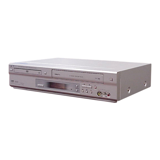
VIDEO CASSETTE RECORDER
HV-DH10
UK Model
French Model
East European Model
West European Model
Latin America Model
Middle East Model
Frequency response
DVD (PCM 96 kHz): 8 Hz to 44 kHz
DVD (PCM 48 kHz): 8 Hz to 22 kHz
CD: 8 Hz to 20 kHz
Signal-to-noise ratio
More than 90 dB
Harmonic distortion
Less than 0.008%
Dynamic range
More than 90 dB (DVD/CD)
Accessory
Antenna cord × 1
Remote control × 1
R03 (size AAA) batteries × 2
•
Design and specifications are subject to change without
notice.
DVD PLAYER/STEREO
HV-DH10G
HV-DH10B
HV-DH10N
HV-DH10E
HV-DH10
Advertisement
Table of Contents

Related Manuals for Aiwa HV-DH10G


Summary of Contents for Aiwa HV-DH10G
- Page 1 HV-DH10 RM-Z481D/Z482D/Z483D/Z484D/Z485D SERVICE MANUAL UK Model HV-DH10G French Model HV-DH10B East European Model HV-DH10N West European Model HV-DH10E Latin America Model Middle East Model HV-DH10 SPECIFICATIONS Tape speed Frequency response General PAL/MESECAM DVD (PCM 96 kHz): 8 Hz to 44 kHz Power requirements SP: 23.39 mm/sec...
- Page 2 WARNING!! Unleaded solder Boards requiring use of unleaded solder are printed with the lead- WHEN SERVICING, DO NOT APPROACH THE LASER EXIT WITH free mark (LF) indicating the solder contains no lead. THE EYE TOO CLOSELY. IN CASE IT IS NECESSARY TO (Caution: Some printed circuit boards may not come printed with CONFIRM LASER BEAM EMISSION, BE SURE TO OBSERVE the lead free mark due to their particular size.)
-
Page 3: Table Of Contents
TABLE OF CONTENTS GENERAL • 3D Surround ······································································ 1-12 • Changing the Audio Track ················································· 1-12 Safety Precautions ····································································· 1-1 • Zoom ················································································· 1-12 WARNING ············································································ 1-1 • Marker Search ··································································· 1-12 Caution ··················································································· 1-1 Special DVD Features ························································· 1-12 Before Use ·················································································... - Page 4 3-2. PRINTED WIRING BOARDS AND SCHEMATIC DIAGRAMS (For Latin America Model) ····················· 3-33 3-2-1. DVD SUB PWB (PCB) ASSEMBLY (COMPONENT SIDE) PRINTED WIRING BOARD ······················· 3-33 3-2-2. DVD SUB PWB (PCB) ASSEMBLY (CONDUCTOR SIDE) PRINTED WIRING BOARD ······················· 3-35 3-2-3. SYSTEM CIRCUIT SCHEMATIC DIAGRAM ····························...
-
Page 5: General
HV-DH10 SECTION 1 This section is extracted from GENERAL instruction manual. (9-885-031-37) ENGLISH Safety Precautions Precautions Caution WARNING Safety To prevent fire or shock hazard, For use of the VCR • This unit operates on 200–240 do not expose the unit to rain or Television programs, films, video V AC, 50 Hz. -
Page 6: Precautions
Before Use (Continued) Front Panel and Display Window Precautions Notes on Discs Handling the Unit Handling Discs When shipping the unit Do not touch the playback side of the disc. The original shipping carton and packing materials Hold the disc by the edges so that fingerprints will not come in handy. -
Page 7: Remote Control For Vcr
Remote Control (Continued) Remote Control (Continued) Remote Control for VCR Preparing the Remote Control Using the Remote Control Point the remote control toward the remote sensor. Inserting the Batteries Things to know before starting This remote control uses the same buttons for VCR and DVD functions (ex. -
Page 8: Additional Connections
Additional Connections Additional Connections (Continued) If your AV receiver is equipped with a Dolby Digital or DTS decoder, you can enjoy high-quality audio playback. Pay TV decoder Pay TV satellite receiver/cable box DECODER DECODER VIDEO VIDEO IN+OUT/DVD OUT AER IAL DVD/VIDEO DVD EXCLUSIVE EURO AV2... -
Page 9: Before Operation - Vcr Part
Before Operation – VCR Part Before Operation – VCR Part (Continued) Press j/l to select the desired menu, then Press OK/ENTER to start the automatic storing To re-start Auto set-up, press i/SETUP. And press j/l to of the channels of the TV stations in your area. press OK/ENTER. -
Page 10: Deleting Tv Stations
Before Operation – VCR Part (Continued) Before Operation – VCR Part (Continued) Press j. Deleting TV Stations Setting the Clock Manually Set the minutes, day, month and year in the same After a short while, the selected station will be way as in step 4. -
Page 11: Initial Settings
Before Operation – DVD Part (Continued) Before Operation – DVD Part (Continued) Menu Language Disc Menu All 8 languages, Original and Other You choose what languages are displayed for the Function (Press i+/k– to select desired option) Options Selection Method setup menu. -
Page 12: Operation With Tape
Before Operation – DVD Part (Continued) Before Operation – DVD Part (Continued) Press i+/k– to select the desired restriction Rating Country Code level and press OK/ENTER. Some DVDs contain parental control information that After specifying the restriction level in the previous applies to the complete disc or certain scenes on the “Rating”... -
Page 13: Showview Programming
Operation with Tape (Continued) Operation with Tape (Continued) Press i+/k– to select the recording type. Press j/l until the blank space between To pause while recording Video Program System (VPS) Press aPAUSE/FRAMEF to avoid recording The Video Program System (VPS) ensures that the ONCE: To record once. -
Page 14: Copying From Dvd To Vcr
Operation with Tape (Continued) Operation with Tape (Continued) Copying from DVD to VCR Recording from another Video On Screen Display Child Lock Recorder This unit allows you to copy the contents of a DVD to You may easily display the current time or tape The control buttons on the front of the unit can be a video cassette tape. -
Page 15: To Set The Color System
Operation with Tape (Continued) Operation with DVD and Video CD Press z (OPEN/CLOSE) to close the tray. To Set the Color System Wide Screen Compatibility 16:9 Disc icon appears in the display window, and Normally the AUTO setting is sufficient. If the This unit can record and play back wide screen playback starts automatically. -
Page 16: Time Search
Operation with DVD and Video CD (Continued) Operation with DVD and Video CD (Continued) 0:00:11 STER. Special DVD Features Time Search Changing the Audio Track Marker Search MARKER SEARCH 1 2 3 4 5 6 7 – – The Time Search function allows you to start playing Press AUDIO repeatedly during playback to hear You can start playback from a memorized point. -
Page 17: Programmed Playback
Programmed Playback Operation with DATA-CD containing JPEG files Press i+/k– to select a track to start playback Press C or OK/ENTER to display a selected file Programmed Playback Displaying JPEGs on the program list. at full size. You can select up to 30 tracks and play them in the •... -
Page 18: Country Code List
Country Code List Country Code List (Continued) Enter the appropriate code number for the initial setting “Country Code” (See page 31). Code Country Code Country Code Country Malta Qatar Tunisia Code Country Code Country Code Country Code Country Mauritius Reunion (French) Tonga Andorra Cocos (Keeling) Islands... -
Page 19: Disassembly
HV-DH10 SECTION 2 DISASSEMBLY NOTE: Follow the disassembly procedure in the numerical order given. 2-1. CASE, FRONT PANEL ASSEMBLY 1 Two screws 4 Case 2 Three screws 3 Two screws 5 Three hooks 6 Three hooks 7 Front panel assembly 2-2. -
Page 20: 2-3. Video Mechanism Deck
2-3. VIDEO MECHANISM DECK 1 Six screws 3 Mechanism deck 2 Flexible cable 2-4. DVD MECHANISM DECK 5 DVD mechanism deck 1 Four screws 3 Flexible cable (PMD01) 4 Flexible cable (PMD03) 2 door case tray... -
Page 21: 2-5. Main Board
2-5. MAIN BOARD 3 Flexible cable (PMD02) 4 Connector (PMD03) 2 Flexible cable (PMD01) 7 Three screws 1 Holder 9 Main board 5 Three screws 6 Two screws 8 Two claws Chassis... -
Page 22: 2-6. Power Pwb (Pcb) Assembly
2-6. POWER PWB (PCB) ASSEMBLY 1 Power cord 3 Screw 4 Three screws 7 Three screws 6 Power PWB (PCB) assembly 9 DVD SUB PWB (PCB) assembly 2 Connector (PMD03) 5 Two claws 8 Claw qa Frame 0 Six screws Chassis 2-7. -
Page 23: Printed Wiring Boards And Schematic Diagrams
HV-DH10 SECTION 3 PRINTED WIRING BOARDS AND SCHEMATIC DIAGRAMS... -
Page 24: Printed Wiring Boards And Schematic
HV-DH10 3-1. PRINTED WIRING BOARDS AND SCHEMATIC DIAGRAMS (For PAL Model) 3-1-1. DVD SUB PWB (PCB) ASSEMBLY (COMPONENT SIDE) PRINTED WIRING BOARD LOCATION GUIDE DVD SUB... -
Page 25: 3-1-2. Dvd Sub Pwb (Pcb) Assembly (Conductor Side) Printed Wiring Board
HV-DH10 3-1-2. DVD SUB PWB (PCB) ASSEMBLY (CONDUCTOR SIDE) PRINTED WIRING BOARD LOCATION GUIDE DVD SUB... -
Page 26: System Circuit
HV-DH10 3-1-3. SYSTEM CIRCUIT SCHEMATIC DIAGRAM No Power on Video signal not appeared System not working or screen is abnormal Program download fail COMBI SCART MTK Digitron all not display Video signal Y '03. 3. 25 SR17444A System not working Video signal Color SYSTEM CIRCUIT... -
Page 27: Rf & Dsp Servo Circuit
HV-DH10 3-1-4. RF & DSP SERVO CIRCUIT SCHEMATIC DIAGRAM CD/DVD LD will not on COMBI SCART MTK '03. 3. 25 SR17445A RF & DSP SERVO CIRCUIT 3-10... -
Page 28: Schematic Diagram
HV-DH10 3-1-5. AUDIO CIRCUIT SCHEMATIC DIAGRAM COMBI SCART MTK '03. 3. 25 SR17447A ADUIO CIRCUIT 3-11 3-12... -
Page 29: Av/Jack Circuit
HV-DH10 3-1-6. AV/JACK CIRCUIT SCHEMATIC DIAGRAM COMBI SCART MTK '03. 3. 25 SR17446A AV /JACK CIRCUIT 3-13 3-14... -
Page 30: 3-1-7. Main Pwb (Pcb) Assembly (Conductor Side) Printed Wiring Board
HV-DH10 3-1-7. MAIN PWB (PCB) ASSEMBLY (CONDUCTOR SIDE) PRINTED WIRING BOARD LOCATION GUIDE MAIN 3-15 3-16... -
Page 31: Printed Wiring Board
HV-DH10 3-1-8. TIMER PWB (PCB) ASSEMBLY PRINTED WIRING BOARD 3-1-9. KEY PWB (PCB) ASSEMBLY PRINTED WIRING BOARD TIMER/KEY 3-17 3-18... - Page 32 HV-DH10 3-1-10. MAIN PWB (PCB) ASSEMBLY SCHEMATIC DIAGRAM (1/5) MAIN 3-19 3-20...
- Page 33 HV-DH10 3-1-11. MAIN PWB (PCB) ASSEMBLY SCHEMATIC DIAGRAM (2/5) MAIN 3-21 3-22...
- Page 34 HV-DH10 3-1-12. MAIN PWB (PCB) ASSEMBLY SCHEMATIC DIAGRAM (3/5) MAIN 3-23 3-24...
- Page 35 HV-DH10 3-1-13. MAIN PWB (PCB) ASSEMBLY SCHEMATIC DIAGRAM (4/5) MAIN 3-25 3-26...
- Page 36 HV-DH10 3-1-14. MAIN PWB (PCB) ASSEMBLY SCHEMATIC DIAGRAM (5/5) MAIN 3-27 3-28...
- Page 37 HV-DH10 3-1-15. POWER PWB (PCB) ASSEMBLY PRINTED WIRING BOARD POWER 3-29 3-30...
-
Page 38: Schematic Diagram (1/5)
HV-DH10 3-1-16. POWER PWB (PCB) ASSEMBLY SCHEMATIC DIAGRAM POWER 3-31 3-32... -
Page 39: Printed Wiring Boards And Schematic Diagrams (For Latin America Model)
HV-DH10 3-2. PRINTED WIRING BOARDS AND SCHEMATIC DIAGRAMS (For Latin America Model) 3-2-1. DVD SUB PWB (PCB) ASSEMBLY (COMPONENT SIDE) PRINTED WIRING BOARD DVD SUB 3-33 3-34... -
Page 40: Printed Wiring Board
HV-DH10 3-2-2. DVD SUB PWB (PCB) ASSEMBLY (CONDUCTOR SIDE) PRINTED WIRING BOARD DVD SUB 3-35 3-36... -
Page 41: System Circuit
HV-DH10 3-2-3. SYSTEM CIRCUIT SCHEMATIC DIAGRAM HB-1S1608 MM74HCT244 SR17146A SYSTEM CIRCUIT 3-37 3-38... -
Page 42: Rf & Dsp Servo Circuit
HV-DH10 3-2-4. RF & DSP SERVO CIRCUIT SCHEMATIC DIAGRAM TO/FROM MPEG DSP II SR17147A RF & DSP SERVO CIRCUIT 3-39 3-40... - Page 43 HV-DH10 3-2-5. AUDIO CIRCUIT SCHEMATIC DIAGRAM (TO/FROM VCR POWER) PDV01-PPD01 (TO/FROM VCR SYSTEM) PDV02-PMD01 TO/FROM MPEG TO/FROM JACK TO/FROM MPEG (TO/FROM VCR JACK) PDV03-PMD02 TO/FROM MEMORY SR17150A ADUIO CIRCUIT 3-41 3-42...
-
Page 44: Av/Jack Circuit
HV-DH10 3-2-6. AV/JACK CIRCUIT SCHEMATIC DIAGRAM DAP202K SR17149A AV /JACK CIRCUIT 3-43 3-44... - Page 45 HV-DH10 3-2-7. MAIN PWB (PCB) ASSEMBLY (CONDUCTOR SIDE) PRINTED WIRING BOARD MAIN 3-45 3-46...
- Page 46 HV-DH10 3-2-8. MAIN PWB (PCB) ASSEMBLY SCHEMATIC DIAGRAM (1/7) SR13732E MAIN 3-47 3-48...
- Page 47 HV-DH10 3-2-9. MAIN PWB (PCB) ASSEMBLY SCHEMATIC DIAGRAM (2/7) MAIN 3-49 3-50...
- Page 48 HV-DH10 3-2-10. MAIN PWB (PCB) ASSEMBLY SCHEMATIC DIAGRAM (3/7) DRIVE & RF SR17148A MAIN 3-51 3-52...
- Page 49 HV-DH10 3-2-11. MAIN PWB (PCB) ASSEMBLY SCHEMATIC DIAGRAM (4/7) SR13733D MAIN 3-53 3-54...
- Page 50 HV-DH10 3-2-12. MAIN PWB (PCB) ASSEMBLY SCHEMATIC DIAGRAM (5/7) SR13734A MAIN 3-55 3-56...
- Page 51 HV-DH10 3-2-13. MAIN PWB (PCB) ASSEMBLY SCHEMATIC DIAGRAM (6/7) SR13736D MAIN 3-57 3-58...
- Page 52 HV-DH10 3-2-14. MAIN PWB (PCB) ASSEMBLY SCHEMATIC DIAGRAM (7/7) SR13738A MAIN 3-59 3-60...
-
Page 53: Printed Wiring Board
HV-DH10 3-2-15. TIMER PWB (PCB) ASSEMBLY PRINTED WIRING BOARD 3-2-16. KEY PWB (PCB) ASSEMBLY PRINTED WIRING BOARD TIMER/KEY 3-61 3-62... -
Page 54: Timer/Key Pwb (Pcb) Assembly
HV-DH10 3-2-17. TIMER/KEY PWB (PCB) ASSEMBLY SCHEMATIC DIAGRAM SR14446B TIMER/KEY 3-63 3-64E... -
Page 55: Repair Parts List
HV-DH10 SECTION 4 REPAIR PARTS LIST 4-1. EXPLODED VIEWS NOTE: • -XX, -X mean standardized parts, so they may • Abbreviation The components identified by mark 0or have some differences from the original one. : French model dotted line with mark 0 are critical for safety. •... -
Page 56: 4-1-2. Dvd Mechanism Deck
4-1-2. DVD MECHANISM DECK not supplied not supplied supplied not supplied supplied supplied not supplied not supplied not supplied Ref. No. Part No. Description Remarks Ref. No. Part No. Description Remarks 9-885-039-79 SCREW B-TITE 9-885-039-77 SCREW DRAWING SWERCH16A/ZNBK 9-885-041-44 BASE ASSY MAIN DP7C (DI) (EXCEPT LA) 9-885-039-78 SCREW MACHINE 9-885-039-81 BASE ASSY MAIN (DP4) DI-IDECK (LA) 9-885-039-95 GEAR ASSY RACK (DI) (LA) -
Page 57: Video Mechanism Deck-1
4-1-3. VIDEO MECHANISM DECK-1 supplied not supplied supplied supplied supplied supplied supplied supplied Ref. No. Part No. Description Remarks Ref. No. Part No. Description Remarks 9-885-034-28 OPENER DOOR 9-885-034-72 ARM ASSY F/L 9-885-034-71 GEAR ASSY RACK F/L 9-885-034-22 PLATE ASSY TOP (UK/FR/N/E/LA) 9-885-034-61 SPRING COIL D35(RACK F/L) 9-885-034-70 HOLDER ASSY CST 9-885-034-34 SPRING COIL D35 SWITCH... -
Page 58: Video Mechanism Deck-2
4-1-4. VIDEO MECHANISM DECK-2 supplied supplied supplied supplied supplied Ref. No. Part No. Description Remarks Ref. No. Part No. Description Remarks 9-885-034-65 DRUM ASSY D35-6CH PAL (EXCEPT LA) 9-885-033-84 BASE ASSY P3 9-885-038-90 DRUM ASSY D35-6CH NTSC (LA) 9-885-033-87 BASE ASSY A/C HEAD 9-885-034-44 SCREW D2.6 L4.5 MSWR3/FZY 1 9-885-034-48 SCREW D2.6 L5.0 SWRCH18A 9-885-034-45 SCREW D2.6 L4.0 MSWR3/FZY 1... -
Page 59: Video Mechanism Deck-3
4-1-5. VIDEO MECHANISM DECK-3 supplied Ref. No. Part No. Description Remarks Ref. No. Part No. Description Remarks 9-885-034-49 SCREW D2.6 L6.8 MSWR3/FZY 1 9-885-034-67 BRACKET ASSY L/D(S) 4 9-885-034-10 LEVER F/R (D35) 9-885-039-76 SCREW, +D2.0 SWERCH16A/NIY 9-885-034-54 WASHER STOPPER 9-885-039-94 BELT DECK/MECHA DP2-5, DP7C 9-885-034-07 GEAR DRIVE(D35) 9-885-040-07 BRACKET ASSY L/D(M)-DI 4 9-885-034-09 BRAKE ASSY CAPSTAN... -
Page 60: Electrical Parts List (For Pal Model)
MAIN 6-2. ELECTRICAL PARTS LIST NOTE: • Due to standardization, replacements in the • RESISTORS • Abbreviation parts list may be different from the parts All resistors are in ohms. : French model specified in the diagrams or the components METAL: metal-film resistor : East European model used on the set. - Page 61 MAIN Ref. No. Part No. Description Remarks Ref. No. Part No. Description Remarks < ZENER DIODE > < IC > ZD501 9-885-041-76 DIODE, ZENERS BZX84-C7V5 IC101 9-885-041-82 IC STR-G6351L ZD501 9-885-041-77 DIODE, ZENERS Z02W7.5V IC101 9-885-041-83 IC STR-G6352T ZD501 9-885-033-48 DIODE, ZENERS UZ-5.6BSB (ME) IC103 9-885-032-92 IC KIA431 ZD502...
- Page 62 MAIN TIMER Ref. No. Part No. Description Remarks Ref. No. Part No. Description Remarks < TRANSISTOR > Q201 9-885-039-74 TRANSISTOR CHIP KTC3875S Q202 9-885-041-65 TRANSISTOR 2SK3018 Q203 9-885-041-65 TRANSISTOR 2SK3018 Q204 9-885-039-69 TRANSISTOR 2SA1037K-Q Q205 9-885-039-69 TRANSISTOR 2SA1037K-Q Q401 9-885-039-69 TRANSISTOR 2SA1037K-Q Q404 9-885-039-68 TRANSISTOR KRA103S-T1 Q405...
-
Page 63: Electrical Parts List
MAIN 4-3. ELECTRICAL PARTS LIST (For Latin America Model) Ref. No. Part No. Description Remarks Ref. No. Part No. Description Remarks MAIN BOARD, COMPLETE (NOT SUPPLIED) < VIBRATOR > *********************************** X301 9-885-040-09 RESONATOR, CRYSTAL (3.579575MHz) < DIODE > X301 9-885-040-10 RESONATOR, CRYSTAL (3.579575MHz) X502 9-885-039-16 RESONATOR, CRYSTAL (32.768KHz) D802... - Page 64 SUB PWB TIMER Ref. No. Part No. Description Remarks Ref. No. Part No. Description Remarks 9-885-042-44 SUB PWB ASSY ACCESORIES ************* *********** < DIODE > 9-885-040-24 CABLE ASSY CD FREE RF NTSC 9-885-042-38 INSTRUCTION ASSY VAC601M D201 9-885-039-34 DIODE RB495D TP 9-885-042-40 REMCON ASSY RM-Z481D D401 9-885-039-36 DIODE DAP202K...
- Page 65 MEMO...
- Page 66 HV-DH10 Sony Corporation 2003G1600-1 Home Storage Company 9-929-763-11 ©2003.7 — 98 — Published by Customer Support Div.