Table of Contents
Advertisement
Quick Links
Advertisement
Table of Contents

Related Manuals for Toyotomi Toyostove OPT-91UL

Summary of Contents for Toyotomi Toyostove OPT-91UL
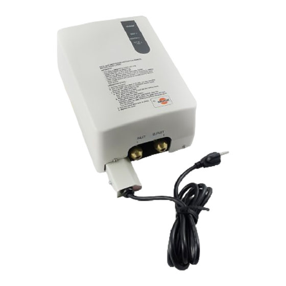
- Page 1 INSTALLATION AND OPERATION INSTRUCTIONS FUEL LIFTER PUMP MODEL OPT - 91UL MPORTANT: READ AND UNDERSTAND INSTRUCTIONS CAREFULLY BEFORE INSTALLING OR USING LIFTER. RETAIN INSTRUCTIONS FOR FUTURE REFERENCE AND CHECK LOCAL CODES AND ORDINANCES FOR PERMITTED USE.
-
Page 2: Table Of Contents
CONTENTS PAGE TITLE SAFETY TIPS Fuel Installation Operation SPECIFICATIONS ELECTRICAL CIRCUIT DIAGRAM COMPONENT PARTS Indication panel SAFETY MECHANISM OPERATION MAINTENANCE STORAGE TROUBLESHOOTING INSTALLATION Unpacking lifter carton Selecting location Safety tips for installation Installation of lifter PIPING Precautions Piping precautions Flaring of pipes Connection of copper pipes Permanent wiring installation Lifting characteristics chart... -
Page 3: Safety Tips
IMPORTANT This lifter is designed and tested for use with Oil Miser, Toyostove and Toyotomi products. OPERATION 1. The maximum lifting height is 26 feet ( 8 m ) . ( Fig. 1 ) Less than 26 ft. -
Page 4: Specifications
SPECIFICATIONS Suction ( Head or fall type ) PUMP TYPE LIFTING HEIGHT ( MAX. ) 26 ft. ( 8 m ) MAXIMUM HORIZONTAL DISTANCE 131 ft. 4 gal./h ( 15 L/H ) at 20 ft. ( 6 m ) OUTLET FLOW RATING INLET PIPE SIZE 3/8"... -
Page 5: Component Parts
COMPONENT PARTS Control box Cover Cover screw Mounting plate Outlet valve lever Motor Fuel opening cap Driving shaft Fuel sump Pump Check valve Fuel strainer Terminal block Power supply cord Funnel Float switch INDICATION PANEL Operation switch Red lamp Green lamp Yellow lamp Control box... -
Page 6: Safety Mechanism
SAFETY MECHANISM 1. Overflow Prevention ( a ) If the lifter is tilted while in operation, the red lamp comes on and the operation stops. ( b ) If an electric part is in malfunction and the oil level exceeds the normal oil level, the red lamp comes on and the operation stops. - Page 7 Note: When first started, the intake line contains air and a muted "THUMPING" sound will be heard. Once the line is filled with fuel the sound will cease. Note: If this does not stop until just before the motor stops, air is leaking into the pipe.
-
Page 8: Maintenance
Note: If the yellow lamp or green lamp flashes when the operation switch is OFF position, the green Control box Outlet valve lamp will flash and the motor will start rotating lever OPERATION switch to perform lifting for about 5 to 12 minutes when turming the operation switch to ON. -
Page 9: Storage
Note: To catch the fuel and water that will drain out, set a half gallon container under the unit. ( b ) Water and fuel will be discharged together. ( c ) Tighten the two ( 2 ) drain screws. ( d ) Operate the lifter for a while to confirm that no fuel is leaking from the drain screws. -
Page 10: Troubleshooting
TROUBLESHOOTING Sympton Cause Solution Red lamp ON. - Too much fuel put in fuel - Let oil level go down, then sump. turn it ON. - Lifter tilted by mistake. - Correct tilt. Turn operation switch to OFF, then turn it - Upper limit float switch - Replace float switch. -
Page 11: Installation
Green lamp ON. - Lower limit float switch - Replace fioat switch. defective. - Pump and/or motor lock. - Replace pump and/or motor. - Pump valve lock. - Replace the pump. All lamps flash. - Fuel consumption - Consumption is too much larger than lifter can pump for lifter pump add another lifter pump. -
Page 12: Selecting Location
SELECTING LOCATION CAUTION: This lifter is for indoor use only. Check local codes and ordinances for permitted uses. 1. Select a safe and solid place to install the lifter. 2. Select a place easy to inspect and maintain. 3. Select a location away from direct sunlight and heat sources. 4. -
Page 13: Installation Of Lifter
4. If a fuel line is run to one heater on the first floor from the main fuel tank by means of Outlet side natural gravity and another heater on the Inlet side second floor by the use of this lifter, then the branch main Less than point of the pipes for these two heaters should be... - Page 14 2. Make four ( 4 ) small holes on the wall as per the 6.06" mounting dimension diagram. ( Fig. 13 ) 3.03" Small hole 1.06" 0.94" Fig. 13 3. Fix the four ( 4 ) mounting rubbers to the wall by Mounting rubber using the wood screws and the washers.
-
Page 15: Piping
PIPING PRECAUTIONS 1. Use 3/8 in. ( 9.53 mm ) in outside diameter and not less than 0.032 in. ( 0.8 mm ) thickness copper tubing. Note: The copper tubing may not be accepted by local building inspection authorities. Check local codes and ordinances for permited use. In these instances, the piping may need to be made of wrought iron or steel. -
Page 16: Flaring Of Pipes
( b ) The large diameter horizontal piping should not be installed at a higher level than the bottom of the fuel tank. As it will cause the pumps to overload and reguire excessive time for Main fuel tank suction or the lifter to be incapable of suction. ( Fig. -
Page 17: Permanent Wiring Installation
PERMANENT WIRING INSTALLATION WARNING: Make sure power supply cord is disconnected to avoid any electric shock before servicing. Electric shock may cause serious injury. It is recommended that installation be conducted by a licensed electrician. 1. Remove two ( 2 ) screws and junction box cover. 2. -
Page 18: External Fuel Supply Installation Kit
EXTERNAL FUEL SUPPLY INSTALLATION KIT ( OPTION ) PART # 10005098 Check Valve Fusible Valve Bleed Screw 3/8" Half Union Main Fuel tank 3/8" Flare Nut Oil Filter 3/4" 3/8" Bushing × 3/8" Tube To Lifter 3/8" 2" Nipple × 3/8"... -
Page 19: Parts List
PARTS LIST REF# PART# PART NAME REF# PART# PART NAME 20459824 Fuel opening cap 20459882 Drive shaft 20459852 Strainer gasket 20459850 Fuel strainer 20459880 Drain packing 20475535 Power supply cord 20477546 Cover 20459819 Pump assembly 20459829 Mounting plate 20477576 Switch circuit 20459837 Motor assembly 20477512... - Page 20 WHO IS COVERED: The original purchaser at retail. WHAT WE WILL DO: TOYOTOMI will either repair or replace, at its option, all defective parts free of charge that are covered by this limited warranty on a carry-in basis, to your nearest authorized dealer or distributor of TOYOTOMI.