Table of Contents
Advertisement
Quick Links
Advertisement
Table of Contents
Troubleshooting

Related Manuals for Omron F3SJ-B0185P25-01TS


Summary of Contents for Omron F3SJ-B0185P25-01TS
- Page 1 Safety Light Curtain F3SJ-B P25-01TS Series User's Manual Cat. No. SCHG-734C...
- Page 2 Original instructions Introduction Thank you for purchasing the F3SJ-B Series Safety Light Curtain (hereinafter referred to as the "F3SJ-B"). This is the instruction manual describing the use of F3SJ-B. Always heed the following points when using the F3SJ-B: Be sure to have F3SJ-B be handled by a "Responsible Person" who is well aware of and familiar with the machine to be installed. The term "Responsible Person"...
- Page 3 2. The F3SJ-B is electro-sensitive protective equipment (ESPE) in accordance with European Union (EU) Machinery Directive Index Annex V, Item 2. 3. EC Declaration of Conformity OMRON declares that the F3SJ-B is in conformity with the requirements of the following EC Directives: Machinery Directive 2006/42/EC EMC Directive 2004/108/EC 4.
-
Page 4: Terms And Conditions Agreement
(a) Exclusive Warranty. Omron's exclusive warranty is that the Products will be free from defects in materials and workmanship for a period of twelve months from the date of sale by Omron (or such other period expressed in writing by Omron). Omron disclaims all other warranties, express or implied. - Page 5 Performance Data. Data presented in Omron Company websites, catalogs and other materials is provided as a guide for the user in determining suitability and does not constitute a warranty. It may represent the result of Omron's test conditions, and the user must correlate it to actual application requirements.
-
Page 6: Precautions On Safety
Precautions on Safety Regarding the alert symbols and meanings used for the safe uses In order to use the F3SJ-B safely, the precautions listed in this manual indicated by alert symbols and descriptions must be followed. Failure to follow all precautions and alerts may result in an unsafe use or operation. - Page 7 For installation Make sure to test the operation of the F3SJ-B after installation to verify that the F3SJ-B operates as intended. Make sure to stop the machine until the test is complete. Unintended function settings may cause a person to go undetected, resulting in serious injury. Make sure to install the F3SJ-B at the safe distance from the hazardous part of the equipment.
- Page 8 Perform an inspection for all F3SJ-B as described in "Chapter 5 Checklists". For wiring Connect the load between the output and 0 V line (PNP output). Connecting the load between the output and +24 V line will result in a dangerous condition because operation is reversed to "ON when blocked".
- Page 9 Other To use the F3SJ-B in PSDI mode (Reinitiation of cyclic operation by the protective equipment), you must configure an appropriate circuit between the F3SJ-B and the machine. For details about PSDI, refer to OSHA1910.217, IEC 61496-1, and other relevant standards and regulations.
-
Page 10: Precautions For Safe Use
Precautions for Safe Use Make sure to observe the following precautions that are necessary for ensuring safe use of the product. Do not install the F3SJ-B in the following types of environments: - Areas exposed to intense interference light, such as direct sunlight - Areas with high humidity where condensation is likely to occur - Areas where oil mist or corrosive gases are present - Areas exposed to vibration or shock levels higher than in the specification provisions... - Page 11 •When extending the communication line with a cable (twisted-pair wire) other than the dedicated cable (F39-JD), use a cable with the same or superior specifications. Connect the shield to the 0V line. Cable specification (extension cable) p.67 •Properly perform the wiring after confirming the signal names of all the terminals. •Be sure that there is nothing in the detection zone and the stable-state indicator is turned ON after power is turned ON.
- Page 12 F3SJ-B User’s Manual...
-
Page 13: Table Of Contents
Contents Legislation and Standards Terms and Conditions Agreement Precautions on Safety Precautions for Safe Use viii Precautions for Correct Use viii Chapter1 Overview and Specifications Basic Configuration and Names Model Overview Internal (LED) Indicator Display Pattern Ratings/Specifications Model/Current Consumption List Chapter2 System Configuration and Functions Wiring Diagrams... - Page 14 When Using Replacement Brackets When Using Contact Mount Brackets When Using Spatter Protection Cover Mounting Mounting Method Number of Brackets Required Mounting Procedure Wiring Wiring Precautions Power Supply Unit Wiring Method Chapter4 Input/Output Circuit and Applications Input/Output Circuit Wiring Examples Using F3SJ-B Only Connecting a F3SJ-B to Various Controllers Using a reduced wiring connector for F3SJ-B...
-
Page 15: Chapter1 Overview And Specifications
Chapter1 Overview and Specifications Basic Configuration and Names Model Overview Internal (LED) Indicator Display Pattern Ratings/Specifications Model/Current Consumption List F3SJ-B User’s Manual... -
Page 16: Basic Configuration And Names
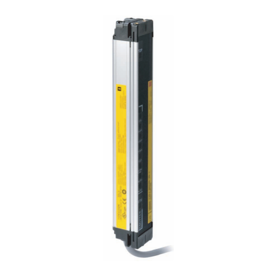
Overview and Specifications Basic Configuration and Names This section describes the system configuration and part names of the F3SJ-B. Beam center-line mark Beam Receiver Indicator Emitter Connection cable (Black) Connection cable (Gray) Extension cable Component Model Description Emitter, receiver F3SJ-BP25--01TS Select a type name based on the required protective height. -
Page 17: Model Overview
Overview and Specifications Model Overview Functions: external test, lockout reset, external device monitoring, auxiliary output and series connection. F3SJ-B User’s Manual... -
Page 18: Internal (Led) Indicator Display Pattern
Overview and Specifications Internal (LED) Indicator Display Pattern Receiver Emitter 1. Top-beam-state indicator (Blue) 1. Top-beam-state indicator (Blue) 2. Stable-state indicator (Green) 2. Stable-state indicator (Green) 3. ON/OFF-state indicator (Green/Red) 3. ON/OFF-state indicator (Green/Red) 4. Lockout indicator (Red) 4. Lockout indicator (Red) 5. - Page 19 Overview and Specifications Emitter Internal indicator Blinking Turns ON when the top beam is receiving Blinks when cap error or connection error Top-beam-state indicator occurs. light. Turns ON when incidence level is 170% or Blinks when the safety output is turned Stable-state indicator more of the output ON threshold.
-
Page 20: Ratings/Specifications
Overview and Specifications Ratings/Specifications The model names of the F3SJ-B contain the 4 digits indicating the protective height (mm). Model F3SJ-BP25-01TS Item Opaque objects Detection capability 25 mm diameter Beam gap 20 mm Number of beams 8 to 102 Protective height 185 to 2,065 mm Lens diameter 5 mm... - Page 21 Cable: Oil resistant PVC Weight (packaged) Weight (g) = (protective height) x 2.7 + 500 Accessories CD (User's Manual), Instruction mannual Refer to "Legislation and Standards" on page i. Applicable standards Safety-related characteristic data See http://www.fa.omron.co.jp/safety_6en/ (EN 61508:2010) F3SJ-B User’s Manual...
-
Page 22: Model/Current Consumption List
Overview and Specifications Model/Current Consumption List Model Current consumption Number of beams Protective height [mm] Basic Type Emitter Receiver (F3SJ-BP25-01TS) F3SJ-B0185P25-01TS 41.0 mA 41.0 mA F3SJ-B0225P25-01TS 43.0 mA 42.0 mA F3SJ-B0305P25-01TS 46.0 mA 43.0 mA F3SJ-B0385P25-01TS 49.0 mA 44.0 mA F3SJ-B0465P25-01TS 52.0 mA... -
Page 23: Chapter2 System Configuration And Functions
Chapter2 System Configuration and Functions Wiring Diagrams Minimum wiring required to check the operation of the F3SJ-B (Wiring for deactivated external device monitoring) Wiring for external device monitoring function Wiring for deactivated external device monitoring function Description of Functions External Test Function Self-test Function Lockout Reset Function Auxiliary Output Function... -
Page 24: Wiring Diagrams
System Configuration and Functions Wiring Diagrams Minimum wiring required to check the operation of the F3SJ-B (Wiring for deactivated external device monitoring) F39-JD A-L F39-JD A-D (Gray) Communication line (+) (Pink) Communication line (-) +24 VDC Power supply Wiring for external device monitoring function F39-JD A-L F39-JD A-D... -
Page 25: Wiring For Deactivated External Device Monitoring Function
System Configuration and Functions Wiring for deactivated external device monitoring function F39-JD A-L F39-JD A-D (Gray) Communication line (+) (Pink) Communication line (-) +24 VDC Power supply : External test switch (connect to 24 V if a switch is not required) : Lockout reset switch (connect to 24 V if a switch is not required) KM1, KM2 : Safety relay with force-guided contact (G7SA) or magnetic contactor... -
Page 26: Description Of Functions
System Configuration and Functions Description of Functions External Test Function This function stops the emission using an external signal. It can be used to verify that a safety system should properly stop (safety output turns OFF) when F3SJ-B is interrupted. To stop the emission, open the test input line or apply voltage of 0 V to 1/2 Vs to the emitter's test input line. -
Page 27: Self-Test Function
System Configuration and Functions Self-test Function The F3SJ-B performs the self-test when power is turned ON (within 2 seconds) to check for errors. Also, it regularly performs the self-test (within a response time) while operating. This function cannot be cancelled. Power supply 2 s max. -
Page 28: Lockout Reset Function
System Configuration and Functions Lockout Reset Function When the cause of the lockout is removed, you can release the lockout by using either of the following methods. •Cycle the power back ON •Reset input Open or apply 0 V to 1/2 Vs to the reset input line (yellow) for 1 s or longer, and then apply a voltage of Vs-3 V to Vs again. -
Page 29: Auxiliary Output Function
System Configuration and Functions Auxiliary Output Function The auxiliary output is used to monitor the status of the F3SJ-B. This output can be connected to a device such as programmable controller. Do not use the auxiliary output for safety applications. Human body may not be detected when F3SJ-B fails, resulting in serious injury. -
Page 30: External Device Monitoring Function
System Configuration and Functions External Device Monitoring Function This function detects malfunctions, such as welding, in external relays (or contactors) that control the hazardous part of a machine. This function constantly monitors that a specified voltage is applied to the receiver's external device monitoring input line, and the system enters lockout state when an error occurs. -
Page 31: Chapter3 Wiring/Installation
Chapter3 Wiring/Installation Installation Conditions Detection Zone and Approach Safety Distance Distance from Reflective Surfaces Mutual Interference Prevention Series Connection Connection Procedure Dimensions When Using Top/Bottom and Intermediate Brackets When Using Intermediate Brackets Only (Free-Location Mounting) 31 When Using One-touch Brackets When Using Replacement Brackets When Using Contact Mount Brackets When Using Spatter Protection Cover... -
Page 32: Installation Conditions
Wiring/Installation Installation Conditions Detection Zone and Approach Install a protective structure so that the hazardous part of a machine can only be reached by passing through the sensor's detection zone. Install the sensors so that part of the person is always present in the detection zone and no blind spot is generated when working in a machine's hazardous zones. -
Page 33: Safety Distance
Wiring/Installation Safety Distance The safety distance is the distance that must be set between the F3SJ-B and a machine's hazardous part to stop the hazardous part before a person or object reaches it. The safety distance varies according to the standards of each country and the individual specifications of each machine. Always refer to relevant standards. - Page 34 Wiring/Installation If a person approaches the detection zone of the F3SJ-B horizontally Use K = 1,600 mm/s and C = (1200 - 0.4 x H) in formula (1) for calculation. Note that C must not be less than 850 mm. Safety distance (S) S = 1,600 mm/s x (Tm + Ts) + 1200 - 0.4 x H Hazard...
-
Page 35: Distance From Reflective Surfaces
Wiring/Installation Distance from Reflective Surfaces Install the sensor system so that it is not affected by reflection from a glossy surface. Failure to do so may hinder detection, resulting in serious injury. Install the sensor system at distance D or further from highly reflective surfaces such as metallic walls, floors, ceilings, or workpieces, as shown below. - Page 36 Wiring/Installation Alternate the direction of emission between two sets (alternation) Aligned vertically Aligned horizontally Receiver Emitter Emitter Receiver Emitter Receiver Receiver Emitter Aligned fore and aft Receiver Emitter Emitter Receiver If two sets of F3SJ-Bs are installed near each other, reflection from the surfaces may cause mutual interference.
-
Page 37: Series Connection
Wiring/Installation Series Connection Up to three sets of F3SJ-Bs can be series-connected. Series connection allows them to be used as a safety light curtain, requiring only one set to be wired to a controller and preventing mutual interference. If any one set of series-connected F3SJ-B is blocked, both of the safety outputs turn OFF. The indication LED for each F3SJ-B turns ON separately. - Page 38 Wiring/Installation Properly connect an emitter to another emitter, and a receiver to another receiver, as shown below. Do not face different models of emitters Do not series-connect an emitter and receiver. They will enter lockout state. and receivers toward each other. They will enter lockout state or will be unable to detect objects.
-
Page 39: Connection Procedure
Wiring/Installation Connection Procedure Remove the caps from the primary sensor. Loosen the screw (M3 cross-shaped) to remove the cap. Use the F39-JBR2W series connection cable for extension to connect them. When changing the connection distance between the F3SJ-Bs, connect a F39-JDB double-ended connector cable (sold separately). -
Page 40: Dimensions
Wiring/Installation Dimensions 42.8 M12 IP67 connector (plug) [Unit: mm] F3SJ-B User’s Manual... -
Page 41: When Using Top/Bottom And Intermediate Brackets
Wiring/Installation When Using Top/Bottom and Intermediate Brackets Backside mounting Top/Bottom Bracket dia.9 (F39-LJB1) 2-M8 4-M5 Intermediate Bracket (F39-LJB2) 2-M5 2-M5 Top/Bottom Bracket (F39-LJB1) <M5 screw fixed> <M8 screw fixed> [ Unit : mm ] Dimensions A to E and P C+69 C+42.2 4-digit number of the type name (protective height) - Page 42 Wiring/Installation Side mounting dia.9 Top/Bottom Bracket (F39-LJB1) 2-M8 4-M5 Intermediate Bracket (F39-LJB2) 2-M5 2-M5 Top/Bottom Bracket (F39-LJB1) <M5 screw fixed> <M8 screw fixed> [ Unit : mm ] Dimensions A to E C+69 C+42.2 4-digit number of the type name (protective height) C-45 Depends on the protective height.
- Page 43 Wiring/Installation Dimensions of Top/Bottom Brackets dia.9 Material : Stainless [ Unit : mm ] Dimensions of Intermediate Brackets (backside mounting) Material : Zinc die-cast [ Unit : mm ] F3SJ-B User’s Manual...
- Page 44 Wiring/Installation Dimensions of Intermediate Brackets (side mounting) Material : Zinc die-cast [ Unit : mm ] F3SJ-B User’s Manual...
-
Page 45: When Using Intermediate Brackets Only (Free-Location Mounting)
Wiring/Installation When Using Intermediate Brackets Only (Free-Location Mounting) Backside mounting Intermediate Bracket (F39-LJB2) Intermediate Bracket (F39-LJB2) 4-M5 [ Unit : mm ] Dimensions C and F 4-digit number of the type name (protective height) Depends on the protective height. See the table below. Dimensions F Protective height Number of Intermediate Brackets... -
Page 46: Mounting
Wiring/Installation • Mounting with one Intermediate Bracket • Mounting with three Intermediate Brackets • Mounting with four Intermediate Brackets 2-M5 6-M5 8-M5 [Unit: mm] F3SJ-B User’s Manual... - Page 47 Wiring/Installation Side mounting Intermediate Bracket (F39-LJB2) Intermediate Bracket (F39-LJB2) [ Unit : mm ] Dimensions C and F 4-digit number of the type name (protective height) Depends on the protective height. See the table below. Dimensions F Protective height Number of Intermediate Brackets Dimensions F 0185 to 0225...
- Page 48 Wiring/Installation • Mounting with one Intermediate Bracket • Mounting with three Intermediate Brackets • Mounting with four Intermediate Brackets 2-M5 6-M5 8-M5 [Unit: mm] F3SJ-B User’s Manual...
-
Page 49: When Using One-Touch Brackets
Wiring/Installation When Using One-touch Brackets Backside mounting One-touch Bracket (F39-LJB3-M6 or F39-LJB3-M8) 2-M6 2-M8 One-touch Bracket (F39-LJB3-M6 or F39-LJB3-M8) <M6 screw fixed> <M8 screw fixed> [ Unit : mm ] Dimensions C and F 4-digit number of the type name (protective height) Depends on the protective height. - Page 50 Wiring/Installation • Mounting with three One-touch Brackets • Mounting with four One-touch Brackets 4-M6 4-M8 3-M6 3-M8 <M6 screw fixed> <M8 screw fixed> <M6 screw fixed> <M8 screw fixed> [Unit: mm] F3SJ-B User’s Manual...
- Page 51 Wiring/Installation Side mounting One-touch Bracket (F39-LJB3-M6 or F39-LJB3-M8) 2-M6 2-M8 One-touch Bracket (F39-LJB3-M6 or F39-LJB3-M8) <M6 screw fixed> <M8 screw fixed> [ Unit : mm ] Dimensions C and F 4-digit number of the type name (protective height) Depends on the protective height. See the table below. Dimensions F Protective height Number of Intermediate Brackets...
- Page 52 Wiring/Installation • Mounting with three One-touch Brackets • Mounting with four One-touch Brackets 4-M6 4-M8 3-M6 3-M8 <M6 screw fixed> <M8 screw fixed> <M6 screw fixed> <M8 screw fixed> [Unit: mm] F3SJ-B User’s Manual...
- Page 53 Wiring/Installation Dimensions of One-touch M6 Bracket Dimensions of One-touch M8 Bracket dia.8.2 dia.6.2 dia.13 dia.17 Material : Stainless Material : Stainless Dimensions of Intermediate Bracket + One-touch Bracket (backside mounting) dia.22 (32.1) (32.1) dia.22 Material : Zinc die-cast [ Unit : mm ] ...
-
Page 54: When Using Replacement Brackets
Wiring/Installation When Using Replacement Brackets Backside mounting Replacement Bracket (F39-LJB4) 4-M5 Replacement Bracket (F39-LJB4) [ Unit : mm ] Dimensions A to C C+159 C+86 4-digit number of the type name (protective height) Bracket mounting procedure (Mounting) p.47 If the protective height is more than 1105 mm, use Intermediate Brackets of the quantities and locations according to the dimensions described on page 27 "When Using Top/Bottom and Intermediate Brackets". - Page 55 Wiring/Installation Side mounting Replacement Bracket (F39-LJB4) 4-M5 Replacement Bracket (F39-LJB4) [ Unit : mm ] Dimensions A to E and P C+159 C+86 4-digit number of the type name (protective height) Bracket mounting procedure (Mounting) p.47 If the protective height is more than 1105 mm, use Intermediate Brackets of the quantities and locations according to the dimensions described on page 27 "When Using Top/Bottom and Intermediate Brackets".
- Page 56 Wiring/Installation Dimensions of replacement bracket Material: Stainless [ Unit : mm ] F3SJ-B User’s Manual...
-
Page 57: When Using Contact Mount Brackets
Wiring/Installation When Using Contact Mount Brackets Backside mounting Contact Mount Bracket Dia. 9 (F39-LJB5) 2-M8 4-M5 Contact Mount Bracket (F39-LJB5) <M5 screw fixed> <M8 screw fixed> Dimensions A to D C+69 C+47.5 4-digit number in the Model name (protective height) C-45 - The protective height of the F3SJ-E/B series that supports the contact mount bracket is limited. - Page 58 Wiring/Installation Side mounting Contact Mount Bracket Dia. 9 (F39-LJB5) 2-M8 4-M5 Contact Mount Bracket (F39-LJB5) <M5 screw fixed> <M8 screw fixed> Dimensions A to D C+69 C+47.5 4-digit number in the Model name (protective height) C - 45 - The protective height of the F3SJ-E/B series that supports the contact mount bracket is limited. Protective height allowed for mounting: 185 mm to 1,105 mm.
- Page 59 Wiring/Installation Dimensions of contact mount bracket dia. 9 Material: Stainless (Unit: mm) F3SJ-B User’s Manual...
-
Page 60: When Using Spatter Protection Cover
Wiring/Installation When Using Spatter Protection Cover Dimensions of Spatter Protection Cover F39-HB [ Unit : mm ] Material: PC (Protection cover) □□□□ - 21mm Assembly Dimensions [ Unit : mm ] F3SJ-B User’s Manual... -
Page 61: Mounting
Wiring/Installation Mounting Mounting Method Mounting methods include use of Top/Bottom Brackets, Top/Bottom Brackets + Intermediate Brackets, Intermediate Brackets only (Free-Location Mounting) and use of One-touch Brackets. Any of these mounting methods allows the user to use the same bracket for the backside mounting and side mounting. -
Page 62: Mounting Procedure
Wiring/Installation Mounting Procedure Using Top/Bottom Bracket only Attach Top/Bottom Brackets and tighten them using the included hexagon socket head cap screws (M3 x 6). Tighten the hexagon socket head cap screws (M3 x 6) with the torque at 0.54 N•m (recommended). - Page 63 Wiring/Installation Turn ON the sensor to perform beam alignment. Move the emitter from side to side (Figure 3) to align it to a center position where the stable-state indicator (STB) is turned ON while checking the top beam state and bottom beam state with the top- beam-state indicator (TOP) and bottom-beam-state indicator (BTM).
- Page 64 Wiring/Installation When Using Top/Bottom + Intermediate Brackets Loosen the hexagon socket head cap screws (M3 x 18) of Intermediate Bracket (3) and change the direction of Intermediate Bracket (2) according to its mounting direction. (Figure 6 and 7) Next, loosen the hexagon socket head cap screws (M3 x 12) of Intermediate Bracket (1) so that it can be mounted to the case of the sensor.
- Page 65 Wiring/Installation Attach a Top/Bottom Bracket and lightly tighten it using the included hexagon socket head cap screws (M3x6). Tighten the hexagon socket head cap screws (M3 x 6) with the torque at 0.54 N•m (recommended). Loosen the hexagon socket head cap screws (M3 x 6), prepare brackets for backside or side mountings, and then lightly tighten them with the hexagon socket head cap screws (M3 x 6).
- Page 66 Wiring/Installation Tighten the screws to mount to the wall by the order of Top/Bottom and Intermediate Brackets. (Figure 11) Tighten the screws to secure Tighten the screws to secure the Top/Bottom Brackets the Intermediate Bracket (3) and the wall. and the wall. Figure 11 Screws to mount the brackets to the wall are not included.
- Page 67 Wiring/Installation Tighten the lightly tightened hexagon socket head cap screws (M3 x 6, M3 x 18) to prevent rotation of the Top/Bottom Brackets and Intermediate Bracket. (Figure 14) Tighten the hexagon socket head cap screws (M3 x 6, M3 x 18) with the torque at 0.54 N•m (recommended).
- Page 68 Wiring/Installation When using Intermediate Bracket (Free-Location Mounting) Loosen the hexagon socket head cap screws (M3 x 18) of Intermediate Bracket (3) and change the direction of Intermediate Bracket (2) according to its mounting direction. (Figure 15 and 16) Next, loosen the hexagon socket head cap screws (M3 x 12) of Intermediate Bracket (1) so that it can be mounted to the case of the sensor.
- Page 69 Wiring/Installation Slide the Intermediate Brackets to the mounting position of the wall. (Figure 18) Backside mounting Side mounting Adjust to the mounting position Figure 18 Screws to mount the brackets to the wall are not included. Tighten the screws that fix the Intermediate Bracket and the wall. (Figure 19) Tighten the screws to secure Tighten the screws to secure the Intermediate...
- Page 70 Wiring/Installation Turn ON the sensor to perform beam alignment. Move the emitter from side to side (Figure 21) to align it to a center position where the stable-state indicator (STB) is turned ON while checking the top beam state and bottom beam state with the top- beam-state indicator (TOP) and bottom-beam-state indicator (BTM).
- Page 71 Wiring/Installation When using One-touch Bracket <Precautions on mounting the sensor using One-touch Brackets> When using two One-touch Brackets to mount a sensor, the combination of One-touch M6 Bracket (or One-touch M8 Bracket) and Intermediate Bracket at the both ends of the sensor must be positioned opposite each other.
- Page 72 Wiring/Installation Loosen the hexagon socket head cap screws (M3 x 18) of Intermediate Bracket (3) and change the direction of Intermediate Bracket (2) according to its mounting direction. (Figure 24 and 25) Next, loosen the hexagon socket head cap screws (M3 x 12) of Intermediate Bracket (1) so that it can be mounted to the case of the sensor.
- Page 73 Wiring/Installation Mount One-touch M6 Brackets (or M8 Brackets) to the aluminum profile according to the position where the sensor is mounted. The positions of One-touch M6 Brackets (or M8 Brackets) mounted to the emitter and receiver must be aligned with each other. To mount Brackets to the aluminum profile, insert a T-slide nut into the profile in advance with the recommended tightening torque of 11.0 N•m.
- Page 74 Wiring/Installation Slide the Intermediate Bracket mounted at the top of the sensor to insert it into the One-touch M6 Bracket (or One-touch M8 Bracket) mounted to the aluminum profile, and then tighten the hexagon socket head cap screws (M3 x 12) on Intermediate Bracket (1) to secure the sensor. (Figure 29) Tighten the hexagon socket head cap screws (M3 x 12) with the torque at 0.54 N•m (recommended).
- Page 75 Wiring/Installation Turn ON the sensor to perform beam alignment. Move the emitter from side to side (Figure 30) to align it to a center position where the stable-state indicator (STB) is turned ON while checking the top beam state and bottom beam state with the top- beam-state indicator (TOP) and bottom-beam-state indicator (BTM).
-
Page 76: Wiring
Wiring/Installation Wiring Wiring Precautions Apply double or enhanced insulation from hazardous voltage to all input and output lines. Failure to do so may result in electric shock. Connect the load between the output and 0 V line (PNP output). Connecting the load between the output and +24 V line will result in a dangerous condition because operation is reversed to "ON when blocked". -
Page 77: Power Supply Unit
"circuit protection such as a fuse is used to limit the current, which has a rating of 4.2 A max." (24 VDC power supply). Recommended power supply: OMRON S8VS (30 W, 60 W) These products are approved by UL listing (UL 508, class 2 power supply), CE marking compatible (EMC/Low Voltage Directive). -
Page 78: Wiring Method
Wiring/Installation Wiring Method Perform wiring according to the following procedure. Connect an emitter cable (F39-JD-L, gray, sold separately) to the emitter's connection cable (gray). Connect a receiver cable (F39-JD-D, black, sold separately) to the receiver's connection cable (black). Connect the 0 V line of the power supply directly to the protective earth (PE). ... - Page 79 Wiring/Installation Double-ended connector cable: Cable for extension and for connection to F3SP-B1P (F39-JDB, sold separately) (Unit: mm) 39.5 Body color: Body color: Black Black M12 IP67 connector M12 IP67 connector Insulated vinyl round cable dia. 6.6, shielded 8-wire (4-pair) (Cross section of conductor: 0.3 mm /insulator diameter: dia.
- Page 80 Wiring/Installation Reduced Wiring Connector System A combination of a double-ended cable for an emitter (F39-JDB-L), a single-ended cable for a receiver (F39-JDA-D), and a reduced wiring connector (optional: F39-CN5) can be used for a reduced wiring system. F3SJ F3SJ Emitter Receiver Reduced Wiring...
- Page 81 Female Blue Blue Male When you need to use a cable that is not specified by OMRON, use a cable that satisfies the following specifications. <Extension cable> 1. 8-wire (0.3 mm or larger x 4 pairs, conductor resistance 0.058 ohms/m max.) 2.
- Page 82 Wiring/Installation F3SJ-B User’s Manual...
-
Page 83: Chapter4 Input/Output Circuit And Applications
Chapter4 Input/Output Circuit and Applications Input/Output Circuit Wiring Examples Using F3SJ-B Only Connecting a F3SJ-B to Various Controllers Using a reduced wiring connector for F3SJ-B F3SJ-B User’s Manual... -
Page 84: Input/Output Circuit
Input/Output Circuit and Applications Input/Output Circuit Entire circuit diagram The numbers in the circles indicate the connector's pin numbers. Indication +24 VDC Brown Test Input Black Test input *1 Circuit Emitter White Not used Interlock Select Main Circuit Input Circuit Yellow Reset input Reset Input... -
Page 85: Wiring Examples
Input/Output Circuit and Applications Wiring Examples Examples of a motor control system using the F3SJ-B are shown below. This chapter shows examples equivalent to ISO 13849-1 (Category 4, PLe). Using F3SJ-B Only - Using external device monitoring function F39-JD A-L F39-JD A-D Communication line (+) (Gray) -
Page 86: Connecting A F3Sj-B To Various Controllers
Input/Output Circuit and Applications Connecting a F3SJ-B to Various Controllers Connecting a F3SJ-B to an F3SP-B1P •Connector can reduce wiring time •Safety relay included - Using external device monitoring function F39-JD B-L F39-JD B-D Test Reset Auxiliary output Safety Safety output 1... - Page 87 Input/Output Circuit and Applications Connecting a F3SJ-B to a G9SA-301 - F3SJ-B settings - Does not use external device monitoring function - G9SA-301 settings - Manual reset mode - Using feedback loop - Using emergency stop switch F39-JD A-L F39-JD A-D Communication line (+) (Gray)
- Page 88 Use G9SB-301-B for auto reset with three N.O. and one N.C. contacts. Use G9SB-200-D for manual reset with two N.O. contacts, or use G9SB-200-B for auto reset with two N.O. contacts. For more information, visit OMRON's website at http://www.omron.com/ F3SJ-B...
- Page 89 Input/Output Circuit and Applications Connecting a F3SJ-B to a G9SX-AD322-T15 •Can be configured for partial control and total control •Can be extended to connect a door switch or a relay unit - F3SJ-B settings - Does not use external device monitoring function - G9SX-AD322-T15 settings - Auto reset mode - Using feedback loop...
- Page 90 Input/Output Circuit and Applications Connecting a F3SJ-B to a G9SP •Emergency stop switch can be connected •Door switch, two hand control, single beam sensor, or relay unit can be used in combination with G9SP. - F3SJ-B settings - Does not use external device monitoring function - G9SP settings - Manual reset mode...
-
Page 91: Using A Reduced Wiring Connector For F3Sj-B
Input/Output Circuit and Applications Using a reduced wiring connector for F3SJ-B •A combination of a cable for reduced wiring (F39-JDBA) and a reduced wiring connector (F39-CN5) can be used for a reduced wiring system. F39-CN5 F39-JD F39-JD +24V DC Power supply Safety... - Page 92 Input/Output Circuit and Applications F3SJ-B User’s Manual...
-
Page 93: Chapter5 Checklists
Chapter5 Checklists Pre-Operation Checklists Maintenance Checklists F3SJ-B User’s Manual... -
Page 94: Pre-Operation Checklists
Checklists Pre-Operation Checklists Make sure to test the operation of the F3SJ-B after installation to verify that the F3SJ-B operates as intended. Make sure to stop the machine until the test is complete. Unintended function settings may cause a person to go undetected, resulting in serious injury. After installation, the highest level administrator must use the following checklist to verify the operation, placing a check mark in each of the boxes. - Page 95 Checklists Operation check while the machine is stopped The test rod is not deformed. Use a test rod with an appropriate diameter for inspection. The sensor can detect a test rod wherever it is in the detection zone. In other words, when a test rod is inserted into the detection zone, the stable-state indicators (STB) turn off and the ON/OFF output- state indicators turn red.
-
Page 96: Maintenance Checklists
Checklists Maintenance Checklists Perform daily and 6-month inspections for the F3SJ-B. Otherwise, the system may fail to work properly, resulting in serious injury. Do not try to disassemble, repair, or modify this product. Doing so may cause the safety functions to stop working properly. - Page 97 Checklists Checking that hazardous parts stop while the machine operates The hazardous parts are movable when nothing is in the detection zone. The hazardous parts stop immediately when a test rod is inserted into the detection zone at three positions: "directly in front of the emitter", "directly in front of the receiver", and "between the emitter and receiver".
- Page 98 Checklists F3SJ-B User’s Manual...
-
Page 99: Chapter6 Appendix
Chapter6 Appendix Troubleshooting Lockout State Troubleshooting Methods Optional Accessories (Sold Separately) Glossary Related Standards International Standards European Standards US Occupational Safety and Health Standards US Standards Canadian Standards SEMI Standards JIS Standards F3SJ-B User’s Manual... -
Page 100: Troubleshooting
Appendix Troubleshooting Lockout State If any error is detected that prevents F3SJ-E/B to continue normal operation, it keeps safety output OFF and transitions to lockout state. Under lockout state, the lockout indicators blink or are ON and other indicators blink based on the failure. Perform actions based on the Troubleshooting described later. Eliminate the cause of the problem. - Page 101 Appendix Emitter Receiver Top-beam-state indicator (Blue) Top-beam-state indicator (Blue) Stable-state indicator (Green) Stable-state indicator (Green) ON/OFF-state indicator (Green/Red) ON/OFF-state indicator (Green/Red) Lockout indicator (Red) Lockout indicator (Red) Power indicator (Green) Communication indicator (Green) Test indicator (Green) Configuration indicator (Green) Internal error indicator (Red) Not Used External device monitoring indicator (Green) Bottom-beam-state indicator (Blue)
-
Page 102: Troubleshooting Methods
Appendix Troubleshooting Methods Identify an error according to the combination of the indicators when the error occurs. See the following troubleshooting tables to take measures. Blink <Indicator status at lockout> Combination of Indicators and Error Description [Error Description] Cap error Ambient light error Safety output error Not Used... - Page 103 Appendix Description Cause and measures Cap error A cap may be detached. Attach the cap properly. The communication line or other wiring may be broken or short-circuited. Check the wiring and cables. A power cable may be detached. Check connectors of the power cable. Communication error If the wiring is extended with cables other than specified, the cables used for extension may not have performance equivalent or greater than the specified cables.
- Page 104 Appendix Description Cause and measures The power supply voltage may have dropped temporarily when the F3SJ-B is in operation. Check for temporary power supply voltage drop (by about 12 VDC) by the influence of the inductive load, etc. If the exclusive power supply is not used, check the power consumption of other connected devices for enough capacity.
-
Page 105: Optional Accessories (Sold Separately)
Appendix Optional Accessories (Sold Separately) Single-ended Connector Cable (Two cables per set, for emitter and receiver) Appearance Model Cable length Specifications F39-JD3A M12 connector (8-pin) - 8 wires + Shield F39-JD7A F39-JD10A 10 m F39-JD15A 15 m F39-JD20A 20 m Double-ended Connector Cable :For connection with F3SP-B1P or cable extension (two cables per set, for emitter and receiver) Appearance... - Page 106 Single-Ended Cable: F39-JD10A-D Note: Also available is a combination of cables for an emitter and a receiver with other lengths than the above. For details, contact Omron. * 1. Double-ended cable for an emitter and single-end cable for a receiver.
- Page 107 Appendix Protect Bar (one piece per set, common for emitter/receiver) (Available soon) Appearance Model Remarks F39-PB The suffix in the model name indicates the same 4-digit number as the protective height (the suffix in the model name) of the F3SJ-B. Only one Protect Bar is included.(Common for emitter/receiver) Purchase two sets if both emitter and receiver require the Protect Bar.
- Page 108 Appendix One-touch M6 Bracket, One-touch M8 Bracket Appearance Model Application Remarks F39-LJB3-M6K Used for mounting Comes with M6 hexagon socket low head Intermediate Bracket cap screws (M6 x 10). with one-touch operation. F39-LJB3-M8K Comes with M8 hexagon socket low head cap screws (M8 x 14).
- Page 109 Appendix Control Unit Appearance Model Output Remarks G9SA-301 Relay with three N.O. • An F39-JDA single-ended cable is and one N.C. required. contacts • A PNP type of F3SJ-B can be connected. • A type of five N.O. and one N.C. contacts is also available.
- Page 110 Appendix Laser Alignment Kit Appearance Model Application Specifications F39-PTJ Beam alignment for Infrared laser diode F3SJ-B. (650 nm wavelength, 1 mW max, JIS CLASS 2, IEC CLASS 2, FDA CLASS Test rod Appearance Model name Diameter F39-TRD25 Dia. 25mm To check operation before use, purchase and use the test rod. F3SJ-B User’s Manual...
-
Page 111: Glossary
Appendix Glossary Term Description Allowable delay time The allowable amount of time from when a state of the safety output changes until a state of the external device monitoring input changes. The F3SJ-B enters lockout if this time is exceeded. Auxiliary output Basic type (basic system) gives inverted signal of safety output, and Basic type (muting system) gives ON output at muting/override. -
Page 112: Related Standards
Appendix Related Standards International Standards • IEC 61496-1: 2008 Safety of machinery - Electro-sensitive protective equipment - Part 1: General requirements and tests • IEC 61496-2: 2006 Safety of machinery - Electro-sensitive protective equipment - Part 2: Particular requirements for equipment using active opto-electronic protective devices •... -
Page 113: Canadian Standards
Appendix • ANSI B11.12: 2005 Roll forming and roll bending machines • ANSI B11.13: 1992 (R2007) Single- and multiple-spindle automatic bar and chucking machines • ANSI B11.15: 2001 Pipe, tube, and shape bending machines • ANSI B11.16: 2003 (R2009) Metal powder compacting presses •... - Page 114 Revision History A manual revision code appears as a suffix to the Catalog number at the bottom of the front and back covers of this manual. Catalog number SCHG-734 C Revision code Revision code Date Revised contents April 2011 First edition November 2012 Added and modified dimensions and notes.
- Page 115 The Netherlands CA 94555 U.S.A Tel: (31)2356-81-300/Fax: (31)2356-81-388 Tel: (1) 510-608-3400/Fax: (1) 510-744-1442 © OMRON Corporation 2011-2014 All Rights Reserved. OMRON (CHINA) CO., LTD. OMRON ASIA PACIFIC PTE. LTD. In the interest of product improvement, Room 2211, Bank of China Tower, No.