Table of Contents
Advertisement
Quick Links
Advertisement
Table of Contents

Related Manuals for Honeywell IF2B


Summary of Contents for Honeywell IF2B
- Page 1 Network Reader User Guide...
- Page 2 Disclaimer Honeywell International Inc. (“HII”) reserves the right to make changes in specifications and other information contained in this document without prior notice, and the reader should in all cases consult HII to determine whether any such changes have been made. The information in this publication does not represent a commitment on the part of HII.
-
Page 3: Table Of Contents
TABLE OF CONTENTS Customer Support ........................vii Technical Assistance ......................vii Product Service and Repair ....................vii Limited Warranty ........................vii Chapter 1 - About the RFID Reader ............... 1 About the IF2............................ 1 About the LEDs......................... 2 About the Ready-to-Work Indicator ................. 3 About the Network and Power Ports ................ - Page 4 Chapter 2 - Configure Network Settings ........... 13 Configure the Settings for Your Network ................13 Configure Ethernet Settings.....................14 Configure Common Network Settings................15 Configure Security ........................16 Control Access Services......................17 Set Up Logins..........................18 Configure the IF2 to Use a Password Server ............18 Change the Default Login...................20 Disable Access Through the Serial Port ...............21 Manage Certificates ........................21...
- Page 5 Unselect Tries ........................29 Session ..........................30 Initial Q ..........................30 Initialization Tries......................30 Schedule Option......................30 ID Tries..........................30 Antenna Tries ........................30 EPCC1G2 Advance Medium Access Mode ............30 Dense Reader Mode.......................31 Antenna Field Strength 1 to 4 ..................31 Antenna Sequence: First through Eighth..............31 Configure the BRI Server ....................31 View the BRI Server Log ......................32 Configure LLRP Settings ......................33 Chapter 4 - Install Applications on the IF2 with Expanded Memory...
- Page 6 Chapter 5 - Manage, Troubleshoot, and Upgrade the IF2 ..... 43 Manage the IF2 ..........................43 Use the Device Configuration Web Service...............43 Open a Serial or USB Connection to the IF2..............44 Open a Serial Connection to the IF2 ................45 Open a USB Connection to the IF2 ................45 Maintain the IF2...........................47 View the System Log ......................47 View the About Screen......................48...
- Page 7 Switch the Low Side with IF2 Power................58 Switching the High Side With External Power ............59 Drive a DC Relay to Control an AC Load...............59 Use the Power Interface ......................60 Appendix A - Specifications ................61 IF2 Specifications ........................61 RFID Specifications........................62 Port Pin Assignments .........................62 GPIO Port ..........................62 GPIO Port Pin Assignments ..................62 Serial Ports (COM1)......................63...
- Page 8 IF2 Network Reader User Guide...
-
Page 9: Customer Support
Honeywell International Inc. provides service for all of its products through service centers throughout the world. To obtain warranty or non-warranty service, return your product to Honeywell (postage paid) with a copy of the dated purchase record. To learn more, go to www.honeywellaidc.com... - Page 10 viii IF2 Network Reader User Guide...
-
Page 11: Chapter 1 - About The Rfid Reader
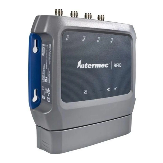
CHAPTER ABOUT THE RFID READER This chapter introduces the IF2 Network Reader, explains the ports and LEDs, and explains how the reader fits into your network. It contains these topics: • About the IF2 • How to Communicate with the IF2 •... -
Page 12: About The Leds
The IF2 comes in a standard configuration with no internal memory, or an expanded memory option. • For the standard IF2, the applications you develop reside on a remote server which communicates with the reader, and all information processing is processed through the server. -
Page 13: About The Ready-To-Work Indicator
Icon Name Description • Green if RF power is being transmitted. RFID status • Red if an antenna fault is detected, or if the reader cannot output the requested RF power level. • Off if RF power is off. Tag ID Flashes when an RFID tag ID is successfully read or written to. -
Page 14: About The Top Panel Ports
Port Description DC power Connects the reader to a 12 volt DC power source. COM1 Connects the IF2 to a desktop PC for configuration. Use an RS-232 null modem cable (P/N 059167). Ethernet 10BaseT/100BaseTx port that connects the reader to your Ethernet network. The reader auto-negotiates with the server to set the best data rate. -
Page 15: How To Communicate With The If2
How to Communicate with the IF2 By default, the IF2 is configured to be a DHCP client and accepts offers from any DHCP server. Therefore, the IF2 will work out of the box if you connect it to your network and use a DHCP server to assign it an IP address. In this case, you config- ure the IF2 using the web browser interface from a desktop PC. - Page 16 3. If DHCP is enabled, press D. DHCP is disabled and the Ethernet Configuration Options screen appears. 4. To set the IP address, press 1 and enter the static IP address in the entry field. 5. Press Enter. The static IP address is set. If you do not need to set the subnet mask or IP router values, you can now continue to configure the IF2 through the web browser interface.
-
Page 17: Use The Web Browser Interface
Use the Web Browser Interface After the IF2 is assigned an IP address, configure the IF2 using the web browser interface. To use the web browser interface, the IF2 must be connected to your wired network. For help, see "Connect the IF2 to Your Network" on page When using the web browser interface, remember that your session automatically terminates if you do not use it for 15 minutes. -
Page 18: Save Configuration Changes
IF2 Secure Login Screen 4. If necessary, enter a user name and password. The default user name is and the default password is . You can define the user name intermec intermec and password. For help, see "Set Up Logins" on page 5. -
Page 19: Disable Help In The Web Browser Interface
IF2 Network Reader Drilling Template Instructions that ship in the box with the IF2. Caution: The IF2 should be professionally installed. For more information, contact your local Honeywell representative. How to Ground the IF2 Caution: Make sure you properly ground the IF2 and all antennas. Proper... -
Page 20: How To Provide Adequate Heat Sinking
Establish the earth ground connection by attaching a ground wire or braid to one of the mounting nuts next to the data interface connectors or to any antenna ter- minal. The base of the IF2 case is magnesium and this surface will NOT provide adequate grounding. -
Page 21: Connect The If2 To Your Network
Mounting screw (4 places) Note: The IF2 is certified to an IP53 environmental rating only when mounted as shown. 5. Ground the IF2. Connect the IF2 to Your Network After you place the IF2 in its mounting location, you can connect it to your network. 1. -
Page 22: Set The Date And Time
Set the Date and Time After you have installed the IF2, you can set the date and time via the web browser interface. 1. Connect to the IF2 via the web browser interface. For help, see "Use the Web Browser Interface" on page 2. -
Page 23: Chapter 2 - Configure Network Settings
CHAPTER CONFIGURE NETWORK SETTINGS This chapter describes how to configure network settings for the IF2 and includes these topics: • Configure the Settings for Your Network • Configure Security • Manage Certificates This chapter assumes that you are familiar with your network, networking terms, and the type of security implemented by your network. -
Page 24: Configure Ethernet Settings
Configure Ethernet Settings This section explains how to configure wired Ethernet settings using the web browser interface. If you are using a DHCP server, you may not need to configure Ethernet settings. For more information, contact your network administrator. 1. From the menu, click Network Configuration or Ethernet in the left pane. The Ethernet screen appears. -
Page 25: Configure Common Network Settings
Ethernet Settings Descriptions Parameter Description Enable DHCP Check this check box if you want the IF2 to get its IP address from a DHCP server. If this check box is not checked, you need to specify the IP address, subnet mask, and IP router for your network. IP Address IP address of the IF2. -
Page 26: Configure Security
1. In the menu, click Network Configuration > Common. The Common screen appears. 2. Configure settings. For help, see the next table. 3. Click Activate Changes to save your changes and immediately make them active. Common Network Settings Descriptions Parameter Description Hostname Name for this IF2. -
Page 27: Control Access Services
• change the default user name and password. For help, see "Set Up Logins" on page • use a password server to maintain a list of authorized users who can configure and manage the IF2. For help, see "Set Up Logins" on page •... -
Page 28: Set Up Logins
Access Services Descriptions Service Description Enable Web Server Enables access to the IF2 via the web browser interface. Select Enable Web Server (Insecure) to allow users to log in using either a nonsecure (HTTP via port 80) or secure (HTTPS via port 443) web interface. - Page 29 1. From the menu, click Security > Passwords. The Passwords screen appears. 2. Check the Enable RADIUS check box. A list of RADIUS configuration items appears. 3. Configure the settings. For help, see the next table. 4. Click Activate Changes. 5.
-
Page 30: Change The Default Login
Change the Default Login If you are not using a password server to authorize user logins, Honeywell recom- mends that you change the default user name and password and create a read- only password. 1. From the main menu, click Security > Passwords. The Passwords screen appears. -
Page 31: Disable Access Through The Serial Port
Disable Access Through the Serial Port When serial port access is disabled, you also disable USB access. When you disable access, you will not be able to configure the IF2 as described in "Assign an Initial IP Address" on page 5. -
Page 32: Install And Uninstall Certificates
The Server Certificate table lists the server certificate that is installed, and the CA Certificate table lists the trusted CA certificate that is installed. Install and Uninstall Certificates Once you have determined that you need to install or uninstall a certificate, use this procedure. - Page 33 4. (Server Certificate only) In the Enter the associated passphrase for this certificate field, carefully enter the passphrase for the certificate. 5. Click Import Certificate. If a Security Alert dialog box appears, click Yes to proceed. IF2 Network Reader User Guide...
- Page 34 IF2 Network Reader User Guide...
-
Page 35: Chapter 3 - Develop And Use Rfid Applications
CHAPTER DEVELOP AND USE RFID APPLICATIONS This chapter explains how you can develop and test RFID applications for the IF2 and IF2 with expanded memory option and includes these topics: • About the IF2 Configurations • RFID Applications and the IF2 •... -
Page 36: Rfid Applications And The If2
BRI protocol, or it can communicate with the IF2 using the Low-Level-Reader Pro- tocol (LLRP). Honeywell recommends that you write and test your application on a development workstation (your desktop PC). The application can access the IF2 BRI interface via TCP on port 2189. -
Page 37: Configure Bri Settings
• LLRP (Low-Level Reader Protocol) - EPCglobal standard for network interfaces between the RFID reader and its controlling software. To configure LLRP settings, see "Configure LLRP Settings" on page Configure BRI Settings This section explains how to configure BRI settings that control reader operation and communication with your application. -
Page 38: Tag Types
Tag Types Check the appropriate check boxes to enable RFID operations for these kinds of tags: • EPC Class 1 Gen 2 (default) • Phillips v1.19 • ISO6B/G1 • ISO6B/G2 This setting is equivalent to the TAGTYPE BRI attribute. Read Tries Sets the maximum number of times the read algorithm is executed before a response is returned to a Read command. -
Page 39: No Tag Report
• For EPC tags, the identifier corresponds to EPCID. Check the check box to enable tag ID reporting. This setting is equivalent to the IDREPORT BRI attribute, and is enabled by default. No Tag Report Enables or disables a NOTAG message, which is sent when no tags are found during execution of a Read, Write, or Lock command. -
Page 40: Session
Session (EPCglobal Class 1 Gen 2 tags only) Sets the command session parameter to the corresponding EPCglobal Class 1 Gen 2 air protocol command (default is Query- Adjust). This setting is equivalent to the SESSION BRI attribute. For more information on this setting, see the EPCglobal Class 1 Gen 2 documentation. -
Page 41: Dense Reader Mode
This setting is equivalent to the EPCC1G2PARAMETERS or EPCC1G2PARMS BRI attribute. Dense Reader Mode Allows the reader to hop between channels within a certain frequency spectrum to prevent other readers in the area from interfering with one another. This setting is equivalent to the DENSEREADERMODE or DRM BRI attribute. Antenna Field Strength 1 to 4 Sets the RF power level (in dBm) for each of the 4 antenna ports. -
Page 42: View The Bri Server Log
1. From the menu, click RFID Services > BRI > BRI Server. The BRI Server screen appears. 2. Change BRI server settings as needed. For help, see the next table. 3. Click Activate Changes to save your changes and immediately make them active. -
Page 43: Configure Llrp Settings
1. Enable BRI logging as described in the previous section, "Configure the BRI Server" on page 2. In the left navigation list, click RFID Services > BRI > BRI Log. The BRI Log screen appears with a list of BRI events. For more information on server events, see the “BRI Event Descriptions”... - Page 44 1. From the menu, click RFID Services > LLRP. The LLRP screen appears. 2. Configure LLRP settings as needed. For help, see the “LLRP Settings Descriptions” table. To disconnect an existing LLRP connection, click Terminate. • • To connect to a remote LLRP client, enter information in the Reader-Initiated Connections section, and then click Initiate.
-
Page 45: Chapter 4 - Install Applications On The If2 With Expanded Memory Option
CHAPTER INSTALL APPLICATIONS ON THE IF2 WITH EXPANDED MEMORY OPTION This chapter explains how you can develop and install applications on the IF2 with Expanded Memory option. • Create a Configuration File • Auto-Start Applications at Boot Time • About .NET Support •... -
Page 46: Auto-Start Applications At Boot Time
RUNAFTERINSTALL specifies whether or not the application should be started immediately after installation. CMDLINE specifies the application name and optional parameters it accepts. Spec- ify command line parameters as if the application is being executed from inside the directory containing the application. Note: Do not use the $JAVA_HOME environment variable in the command line. -
Page 47: Execute Java Applications
For more sophisticated Java development, the IF2 supports the open standard OSGi service-oriented architecture. This allows system administrators to install, uninstall, enable, and disable system services (also known as bundles) without having to reboot the IF2 each time. To use OSGi effectively, you need an OSGi server. -
Page 48: Install Rfid Applications
For more information on the jTDS driver, go to http://jtds.sourceforge.net. Install RFID Applications The IF2 provides up to 96 MB of storage for your applications. You use the web browser interface to install applications on the IF2 as described in the next proce- dure. -
Page 49: About The Edgeware Applications
(or reboot the IF2) for the date and time changes to be made effective. About the Edgeware Applications Edgeware applications are supplied by Honeywell and its partner developers, and provide immediate functionality for your RFID system. The IF2 includes these edgeware applications: •... -
Page 50: Test The Gpio Interfaces
• General purpose input/output (GPIO) testing. For help, see the next section, “Test the GPIO Interfaces.” • Sending BRI commands or BRI script files to the IF2 from an interactive browser interface. For help, see "Send BRI Commands and Running Scripts" on page •... -
Page 51: Use The Workbench
4. Click Load. The script is loaded and run, and return values appear onscreen. Use the Workbench You can create and edit a JavaScript file, load the file on the IF2, and run the file from the Workbench. Note: These instructions assume you understand how to create and edit JavaScript files. 1. - Page 52 IF2 Network Reader User Guide...
-
Page 53: Chapter 5 - Manage, Troubleshoot, And Upgrade The If2
MANAGE, TROUBLESHOOT, AND UPGRADE THE IF2 This chapter includes information on managing the IF2 and includes these topics: • Manage the IF2 • Use the Device Configuration Web Service • Open a Serial or USB Connection to the IF2 • Maintain the IF2 •... -
Page 54: Open A Serial Or Usb Connection To The If2
1. From the menu, click Network Configuration > Device Management. The Device Management screen appears. By default, Device Configuration web services are enabled for either secure or insecure connections. 2. To disable web services over a secure connection, clear the Enable Device Web Services (Secure) check box, and then click Activate Changes. -
Page 55: Open A Serial Connection To The If2
Open a Serial Connection to the IF2 If you are opening a serial connection to the IF2, you need: • a null-modem cable (P/N 059167). • a communications program such as HyperTerminal. Note: If you have Microsoft ActiveSync running on your desktop PC, disable ActiveSync to make the serial port available. - Page 56 1. Create a folder to place the gserial.inf and usb.sys file in. 2. Click Start > Programs > Accessories > Notepad. 3. In Notepad, copy and paste the following text: [Version] Signature="$Windows NT$" Class=Ports ClassGuid={4D36E978-E325-11CE-BFC1-08002BE10318} Provider=%LINUX% DriverVer=08/17/2004,0.0.2.0 ; Copyright(C)2004 Al Borchers (alborchers@steinerpoint.com) [Manufacturer] %LINUX%=GSerialDeviceList [GSerialDeviceList]...
-
Page 57: Maintain The If2
You can open a BRI session. Maintain the IF2 The Maintenance menu lets you view IF2 parameters and statistics, including a list of logged events. You may need this information if you need to call Honeywell Product Support. View the System Log The System Log screen shows events that have been logged by the IF2. -
Page 58: View The About Screen
1. From the menu, click Maintenance > System Log. The System Log screen appears. This screen is read-only. 2. To save the list, click Export log to text file. The log is saved as Syslog.log and appears in the browser window. 3. -
Page 59: Use The Leds To Locate The If2
Use the LEDs to Locate the IF2 You can use the LEDs to help locate a specific IF2 in your location. • In the About This IF2 RFID Reader screen, click Find This Device. All of the LEDs except the Power and Wired LAN LEDs flash. Click Finished Finding This Device to turn off the LEDs. -
Page 60: Restore Default Settings With The Reset Switch
3. Click OK. The IF2 reboots and restores the default configuration. Or, click Cancel to close the confirmation message without restoring defaults. Restore Default Settings with the Reset Switch If you are having problems with the IF2, you can press the reset switch to restore the default settings to the IF2. -
Page 61: Troubleshoot The If2
Make sure all antenna connections are tight and that the cables are in good condition. For help, contact your Honeywell RFID system consultant. • To maximize IF2 performance, make sure you have chosen the correct tag types for your application. - Page 62 You need to know the IF2 IP address to connect directly to the RFID module. To ver- ify that the RFID reader is reading tags, you need a known good RFID antenna and at least one good RFID tag. 1. Make sure the RFID antenna is connected properly to the IF2. 2.
-
Page 63: Problems With Connectivity
Problems With Connectivity When troubleshooting problems with connectivity, make sure you know and under- stand these network-specific items: • TCP/IP settings • COM port settings for serial connections You should also make sure all physical network connectors and cables are in good working order. -
Page 64: Upgrade Firmware
Upgrade Firmware This section explains how to configure and install firmware upgrades on the IF2. Note: To upgrade the firmware, use only .bin files provided by Honeywell. Be sure to contact your RFID system consultant before upgrading. Caution: Make sure the IF2 is connected to a reliable power source before you upgrade the firmware. -
Page 65: Chapter 6 - Use The If2 Gpio Interfaces
USE THE IF2 GPIO INTERFACES This chapter explains how to access the IF2 general purpose input/output (GPIO) interfaces and how to connect industrial controls such as motion sensors or indi- cator lamps to the IF2. This chapter includes the following topics: •... -
Page 66: Use The Input Interfaces
Use the Input Interfaces Each of the four inputs is compatible with input signals of 10 to 36 VDC. Both the high and low signal contacts are exposed and isolated to 1500 V. Input impedance is 1.8 K ohms minimum. GPIO Input Signal Descriptions Signal Description... -
Page 67: Open Collector Input Interface
External input switch +Input -Input 10-48 VDC Twisted pair Isolated Input Interface Open Collector Input Interface The input can be connected to an open collector interface of an external device. This typically implies that the grounds are tied together for the two systems. The common ground can be a source of input noise, so you should follow good ground- ing practices for both the IF2 and the input device. -
Page 68: Switch The High Side With If2 Power
Since the outputs are optically isolated, you can configure each one to switch the high side or the low side of the load. You can power the load directly from the IF2 or from an external power supply. In a typical application, the outputs control indicator lamps that signal good reads or errors. -
Page 69: Switching The High Side With External Power
External indicator lamp 0.25 A maximum +12 V +Output - Output Ground Switching the Low Side of the Output Load Switching the High Side With External Power To use external power (5 to 48 VDC) to switch the high side, connect the Ground pin to the ground system of the external power supply, and connect the positive side of the external supply to the +Output pin. -
Page 70: Use The Power Interface
AC motor + 12 V + Output - Output 120-230 Ground External relay Driving a DC Relay: The external relay provides dry contacts for controlling the AC motor. Note: In many installations, the relay and AC wiring must be placed in an enclosure that meets local fire code regulations. -
Page 71: Appendix A - Specifications
APPENDIX SPECIFICATIONS This appendix includes physical and electrical specifications for the IF2 and infor- mation about the port pin assignments. IF2 Specifications Specifications Values Height 19.9 cm (7.87 in) Length 18.8 cm (7.42 in) Width 4.3 cm (1.7 in) Weight 1 kg (2.2 lb) DC electrical rating 12 V +/- 5%, 30 W... -
Page 72: Rfid Specifications
RFID Specifications Specifications Values Protocols Supported EPCglobal Class 1 Gen 2 ISO 18000-6B Generation 1 ISO 18000-6B Generation 2 Frequency Range 865.6 - 867.6 MHz, or 902 - 928 MHz Frequency Range - 919 - 923 MHz Malaysia Output power Minimum: 1 dBm 865-867 MHz, 900 Maximum: 30.0 dBm... -
Page 73: Serial Ports (Com1)
Description Active Polarity Ground +Output 2 High (10-48 V) Ground +Output 3 High (10-48 V) Ground +Output 4 High (10-48 V) +Input 1 High (10-48 V) +Input 2 High (10-48 V) +Input 3 High (10-48 V) +Input 4 High (10-48 V) 12VDC -Output 1 Low-RTN... -
Page 74: Ethernet Port
Ethernet Port Pin 1 Ethernet Port Pin Assignments Description Ethernet TX+/Spare POE return Ethernet TX-/Spare POE return Ethernet RX+/Spare POE 48 VDC Not used/POE 48 VDC Not used/POE 48 VDC Ethernet RX-/Spare POE 48 VDC Not used/POE return Not used/POE return IF2 Network Reader User Guide... - Page 76 Honeywell 9680 Old Bailes Road Fort Mill, SC 29707 www.honeywellaidc.com ™ 935-040-005 Rev A 04/20...