
Related Manuals for Siemens Argus 8 7SG11


Summary of Contents for Siemens Argus 8 7SG11
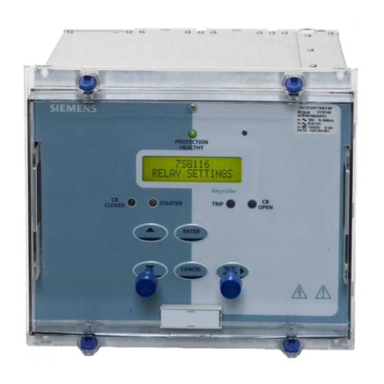
- Page 1 Reyrolle Protection Devices 7SG11 – Argus 8 Voltage and Frequency Relays Answers for energy...
- Page 2 Limited. No part of this document shall be reproduced or modified or stored in another form, in any data retrieval system, without the permission of Siemens Protection Devices Limited, nor shall any model or article be reproduced from this document unless Siemens Protection Devices Limited consent.
- Page 3 Limited. No part of this document shall be reproduced or modified or stored in another form, in any data retrieval system, without the permission of Siemens Protection Devices Limited, nor shall any model or article be reproduced from this document unless Siemens Protection Devices Limited consent.
-
Page 4: Table Of Contents
Table 3 - Output Relay Types ...........................6 Table 4 - Connection Table (E4 Versions) ......................16 Table 5 - Connection Table (E6 Versions) ......................17 Table 6 - Event Codes ............................19 ©2010 Siemens Protection Devices Limited Chapter 1 Page 2 of 20... - Page 5 [2] - INFORMATIVE COMMUNICATIONS INTERFACE : a report detailing all aspects of the communications protocol used in the Argus range of relays is available from Reyrolle Protection. The report reference is 434TM05B. ©2010 Siemens Protection Devices Limited Chapter 1 Page 3 of 20...
-
Page 6: Introduction
A menu-based interface gives user-friendly access to relay settings, meters and operational data. The relay conforms to the relevant IEC 60255 standards. ©2010 Siemens Protection Devices Limited Chapter 1 Page 4 of 20... -
Page 7: Table 1 - Argus 8 - 2 Pole Variants
All features as above AG8 310-312 All features as above * Argus 8 types 304-312 are suitable for 50Hz systems only. Table 2 - Argus 8 - 3 Pole Variants ©2010 Siemens Protection Devices Limited Chapter 1 Page 5 of 20... -
Page 8: Table 3 - Output Relay Types
A trip test feature is provided to exercise the output contacts. For a list of terminal numbers and their usage see Tables 4 and 5 at the back of this section. Status Inputs ©2010 Siemens Protection Devices Limited Chapter 1 Page 6 of 20... - Page 9 (NPS) and zero phase sequence (ZPS) quantities are also derived from the output of the DFT calculation. The DFT ensures that D.C. and harmonics are rejected and so guarantees accurate and stable ©2010 Siemens Protection Devices Limited Chapter 1 Page 7 of 20...
-
Page 10: Protection Functions
Figure 1 - Voltage Element The voltage elements each have a variable hysteresis setting which allows the user to vary the pick-up - drop-off ratio for a particular element. ©2010 Siemens Protection Devices Limited Chapter 1 Page 8 of 20... -
Page 11: Nps Overvoltage Elements
(U/F) or overfrequency (O/F). Each element can be inhibited in four different ways :- If all phase voltages fall below the voltage blocking threshold level. Via a status input inhibit signal. Via any combination of voltage elements starting. ©2010 Siemens Protection Devices Limited Chapter 1 Page 9 of 20... -
Page 12: Two Systems Connection
Primary RMS volts for VA, VB, VC and VO (alternatively VAB, VBC, VCA) • Secondary RMS volts for Va, Vb, Vc, V1, V2 and Vo (alternatively Vab, Vbc, Vca) ©2010 Siemens Protection Devices Limited Chapter 1 Page 10 of 20... -
Page 13: Data Storage
500 event records to be stored in the relay and when the event buffer is full, any new record will over-write the oldest. The following events are logged : ©2010 Siemens Protection Devices Limited Chapter 1 Page 11 of 20... -
Page 14: Fault Data Records
• Waveform Records • Event Records • Fault Data Records • Instrument and meters • Control Functions Communications operation is described in detail in Section 4 of this manual. ©2010 Siemens Protection Devices Limited Chapter 1 Page 12 of 20... -
Page 15: General Alarm Screens
Once the password has been validated, the user is ‘logged on’ and any further changes can be made without re-entering the password. If no more changes are made within 1 hour then the user will automatically be ‘logged off’, re-enabling the password feature. ©2010 Siemens Protection Devices Limited Chapter 1 Page 13 of 20... -
Page 16: Trip Circuit Supervision
The top line of the LCD can be changed to some user-definable identifier or code if preferred. ©2010 Siemens Protection Devices Limited Chapter 1 Page 14 of 20... - Page 17 For a complete list of all possible settings see Section 3 – of this manual. This section also shows all setting ranges and factory default values, as well as including a brief description of each setting function. ©2010 Siemens Protection Devices Limited Chapter 1 Page 15 of 20...
-
Page 18: Table 4 - Connection Table (E4 Versions)
Relay 6 (N/O) Relay 7 (N/O) – – Relay 7 (N/O) Status Input 4 Status Input 3 Status Input 2 (–) Status Common Table 4 - Connection Table (E4 Versions) ©2010 Siemens Protection Devices Limited Chapter 1 Page 16 of 20... -
Page 19: Table 5 - Connection Table (E6 Versions)
Status Input 9 Status Input 8 (–) Status Input 8 Status Input 7 (–) Status Input 7 Status Input 6 (–) Status Input 6 Table 5 - Connection Table (E6 Versions) ©2010 Siemens Protection Devices Limited Chapter 1 Page 17 of 20... - Page 20 RaisedAndCleared Waveform Stored RaisedOnly Remote CTRL Interrupted RaisedOnly Power On Counter Alarm RaisedAndCleared Trip Circuit Fail RaisedAndCleared Trip Count Alarm RaisedAndCleared General Alarm 1 RaisedAndCleared General Alarm 2 RaisedAndCleared ©2010 Siemens Protection Devices Limited Chapter 1 Page 18 of 20...
-
Page 21: Table 6 - Event Codes
F Element 4 Trip RaisedOnly 3Vo Element 1 Trip RaisedOnly 3Vo Element 2 Trip RaisedOnly V2 Element 1 Trip RaisedOnly V2 Element 2 Trip RaisedOnly Table 6 - Event Codes ©2010 Siemens Protection Devices Limited Chapter 1 Page 19 of 20... -
Page 22: Figure 5 - Display Menu Structure
V2 Starters ARE NOT ALWAYS VISIBLE. THEY ARE V2E1 DEPENDENT UPON RELAY TYPE AND VARIOUS CONFIGURATION OPTIONS. Vo Starters 3VoE2 F Starters FE1 FE2 Figure 5 - Display Menu Structure ©2010 Siemens Protection Devices Limited Chapter 1 Page 20 of 20... - Page 23 Limited. No part of this document shall be reproduced or modified or stored in another form, in any data retrieval system, without the permission of Siemens Protection Devices Limited, nor shall any model or article be reproduced from this document unless Siemens Protection Devices Limited consent.
- Page 24 12.3 Emissions ..............................8 12.4 Mechanical ..............................8 Table of Figures Figure 1 - Typical O/V Operate Time Characteristic ....................9 Figure 2 - Typical U/V Operate Time Characteristic ....................9 ©2010 Siemens Protection Devices Limited Chapter 2 Page 2 of 9...
-
Page 25: General
Note : special versions of status input are available for direct operation from 110V and 220V supplies. These do not comply with the ESI 48-4 specification and will operate with a DC current of less than 10mA. ©2010 Siemens Protection Devices Limited Chapter 2 Page 3 of 9... -
Page 26: Setting Ranges
≥ (operate level – hysteresis setting) Operate Time (see Fig.1) – to output contact 0V to 2x setting ≤ 45ms 0V to 1.1x setting ≤ 55ms Reset Time 1.1x to 0.9x setting ≤ 50ms ©2010 Siemens Protection Devices Limited Chapter 2 Page 4 of 9... -
Page 27: Undervoltage Element
Reset Level Operate – 20mHz Operate Time For ROCOF between 0.1-10 Hz/sec Typically < 140ms Maximum < 175ms Typically < 100ms : AG8 - 300 series only Maximum < 150ms ©2010 Siemens Protection Devices Limited Chapter 2 Page 5 of 9... -
Page 28: Underfrequency Element
Continuous Overload AC Voltage 250Vrms ( 353Vpk) Burdens AC Burden AC Burden 110Vrms Input ≤ 0.1VA 63.5Vrms Input ≤ 0.05VA DC Burden DC Burden Quiescent (Typical) 3 Watts 10 Watts ©2010 Siemens Protection Devices Limited Chapter 2 Page 6 of 9... -
Page 29: Output Contacts
IEC 60255-22-2 Class 3 Variation 6kV contact discharge ≤ 5% 8kV air discharge (to fascia) ≤ 5% Radio Frequency Interference - IEC 60255-22-3 Class III Variation 80MHz to 1000MHz, 10V/m ≤ 5% ©2010 Siemens Protection Devices Limited Chapter 2 Page 7 of 9... -
Page 30: Emissions
≤ 5% Seismic Response Mechanical Classification Durability In excess of 10 6 operations Qualification Product :- C compliant to all relevant EU directives. Quality Systems :- accredited to ISO 9001 ©2010 Siemens Protection Devices Limited Chapter 2 Page 8 of 9... - Page 31 Applied Overvoltage (% of setting) Figure 1 - Typical O/V Operate Time Characteristic Typical Instantaneous U/V Operate Time Characteristic Applied Undervoltage (% of setting) Figure 2 - Typical U/V Operate Time Characteristic ©2010 Siemens Protection Devices Limited Chapter 2 Page 9 of 9...
- Page 32 The copyright and other intellectual property rights in this document, and in any model or article produced from it (and including any registered or unregistered design rights) are the property of Siemens Protection Devices Limited. No part of this document shall be reproduced or modified or stored in another form, in any data retrieval system, without the permission of Siemens Protection Devices Limited, nor shall any model or article be reproduced from this document unless Siemens Protection Devices Limited consent.
- Page 33 7 Frequency Menu ..............................6 8 O/P Relay Config Menu............................7 9 Status Config Menu............................8 10 Comms Interface Menu ............................9 11 Data Storage Menu ............................9 12 CB Maintenance Menu............................. 10 ©2010 Siemens Protection Devices Limited Chapter 3 Page 2 of 10...
-
Page 34: System Config Menu
Clock - Set Time HH:MM:SS 00:00:00 sets the current time in HH/MM/SS format. Note that only hours and minutes can be set. The seconds default to zero on pressing the ENTER key ©2010 Siemens Protection Devices Limited Chapter 3 Page 3 of 10... -
Page 35: Voltage Menu
Gn V Element 4 Delay As per Element 1 0.00 sec Gn V Element 4 Hysteresis As per Element 1 Gn V Element 4 O/P Phases As per Element 1 Any 1 ©2010 Siemens Protection Devices Limited Chapter 3 Page 4 of 10... -
Page 36: System A Menu
Gn V Element 4 Setting As per Element 1 Gn V Element 4 Delay As per Element 1 0.00 sec Gn V Element 4 Hysteresis As per Element 1 ©2010 Siemens Protection Devices Limited Chapter 3 Page 5 of 10... -
Page 37: Neutral Voltage Menu
Gn F Element 4 Setting As per Element 1 50.00Hz Gn F Element 4 Delay As per Element 1 0.00 sec Gn F Element 4 Inhib As per Element 1 NONE ©2010 Siemens Protection Devices Limited Chapter 3 Page 6 of 10... -
Page 38: P Relay Config Menu
Gn FE3 Trip RL1..RLn None Gn FE4 Starter RL1..RLn None Gn FE4 Trip RL1..RLn None Gn Status 1 RL1..RLn None sets the output relay(s) operated by Status Input 1 energisation ©2010 Siemens Protection Devices Limited Chapter 3 Page 7 of 10... -
Page 39: Status Config Menu
Alarm 1 message to be displayed on the Gn ALARM ..n S1..Sn None Gn Waveform Trigger S1..Sn None sets the status input(s) which, on energisation, will cause a waveform record to be stored ©2010 Siemens Protection Devices Limited Chapter 3 Page 8 of 10... -
Page 40: Comms Interface Menu
Gn Waveform Trig STA, V, F, NPS, NVD STA+V+NPS+ NVD+F selects which functions trigger a waveform record Gn Waveform Pre-trigger OFF, 10%-100% step 10% selects which functions trigger a waveform record ©2010 Siemens Protection Devices Limited Chapter 3 Page 9 of 10... -
Page 41: Cb Maintenance Menu
This is achieved by selecting one of the output settings defined in the O/P Relay Config Menu. Note that the relay is energised after 10 seconds have elapsed and is energised for only 100 ©2010 Siemens Protection Devices Limited Chapter 3 Page 10 of 10... - Page 42 Limited. No part of this document shall be reproduced or modified or stored in another form, in any data retrieval system, without the permission of Siemens Protection Devices Limited, nor shall any model or article be reproduced from this document unless Siemens Protection Devices Limited consent.
- Page 43 Bit (logical 0) sent to signify the start of a byte during data transmission. Stop Bit Bit (logical 1) sent to signify the end of a byte during data transmission. ©2010 Siemens Protection Devices Limited Chapter 4 Page 2 of 8...
-
Page 44: Introduction
RS232C electrical interface. A suitable converter is the Sigma 4 type, which is available from Reyrolle Protection. ©2010 Siemens Protection Devices Limited Chapter 4 Page 3 of 8... -
Page 45: Parity Setting
Data Echo setting. All relays in an optical ring must have a unique address. Address 255 is reserved as a global broadcast address. ©2010 Siemens Protection Devices Limited Chapter 4 Page 4 of 8... -
Page 46: Modems
If it does not, however, set the local modem to mimic the settings of the remote modem described above. ©2010 Siemens Protection Devices Limited Chapter 4 Page 5 of 8... - Page 47 Personal Computer - Version of the former configuration of Figure 1. It is necessary to make dial-up connection before actual information exchange. Figure 2 - Basic Communications Configuration (Remote) ©2010 Siemens Protection Devices Limited Chapter 4 Page 6 of 8...
- Page 48 - Automatic type : continuous interrogation of all relays by Interface cyclical polling. - Dialogue type comms. can be initialised from MMI also Figure 4 - Data Concentrator Configuration ©2010 Siemens Protection Devices Limited Chapter 4 Page 7 of 8...
- Page 49 Figure 5 - Optical Ring Configuration Serial optical link Local RS232 SIGMA-3 Personal Computer System RS232 Control System Figure 6 - Configuration using the Sigma 3 – Dual Port RS232 Device ©2010 Siemens Protection Devices Limited Chapter 4 Page 8 of 8...
- Page 50 Limited. No part of this document shall be reproduced or modified or stored in another form, in any data retrieval system, without the permission of Siemens Protection Devices Limited, nor shall any model or article be reproduced from this document unless Siemens Protection Devices Limited consent.
- Page 51 Figure 5 – 2 Systems Connection (Ph-N)..................12 Figure 6 – 3 Phase-Neutral Connection .................... 13 Figure 7 – 2 Phase-Phase with Residual Voltage Connection............14 Figure 8 – 3 Phase-Phase Connection ..................... 15 ©2010 Siemens Protection Devices Limited Chapter 5 Page 1 of 16...
-
Page 52: Introduction
UnderVoltage Block output ‘ V Block Alarm ‘ should be mapped to the relevant output relay(s). If a Time delay is needed then the output relay should be connected to a Status input to make use of its Pick-up and Drop-off time delays ©2010 Siemens Protection Devices Limited Chapter 5 Page 2 of 16... -
Page 53: Output Contact Delay Time
This is shown in the diagram below: Volts Nominal Volts ramp-up U/V Setting Operate U/V element will not operate in this region V block Threshold time ©2010 Siemens Protection Devices Limited Chapter 5 Page 3 of 16... -
Page 54: Voltage Element Hysteresis
Also, where a supply to induction motors is lost, the undervoltage relay can be used to detect the loss of supply or to ©2010 Siemens Protection Devices Limited Chapter 5 Page 4 of 16... -
Page 55: Overvoltage Protection
These triplen harmonics appear across the open delta winding even when there is no earth fault on the network and no zero sequence voltage. The relay’s main measuring algorithm being ©2010 Siemens Protection Devices Limited Chapter 5 Page 5 of 16... -
Page 56: Nps Overvoltage Protection
Conversely, if there is an excess of generation in the subsystem then the generator speed will increase causing a proportional frequency ©2010 Siemens Protection Devices Limited Chapter 5 Page 6 of 16... - Page 57 It is important to note that where there is other load shedding equipment on a system, the Argus 8 relay should be set to co-ordinate with it. ©2010 Siemens Protection Devices Limited Chapter 5 Page 7 of 16...
- Page 58 7SG11 Argus 8 Applications Guide Figure 1 – Trip Circuit Supervision Scheme ©2010 Siemens Protection Devices Limited Chapter 5 Page 8 of 16...
- Page 59 7SG11 Argus 8 Applications Guide Figure 2 – 2 Phase-Phase ‘V’ Connection ©2010 Siemens Protection Devices Limited Chapter 5 Page 9 of 16...
- Page 60 7SG11 Argus 8 Applications Guide Figure 3 – 2 Phase-Phase Connection ©2010 Siemens Protection Devices Limited Chapter 5 Page 10 of 16...
- Page 61 7SG11 Argus 8 Applications Guide Figure 4 – Phase-Phase with Residual Voltage Connection ©2010 Siemens Protection Devices Limited Chapter 5 Page 11 of 16...
- Page 62 7SG11 Argus 8 Applications Guide Figure 5 – 2 Systems Connection (Ph-N) ©2010 Siemens Protection Devices Limited Chapter 5 Page 12 of 16...
- Page 63 7SG11 Argus 8 Applications Guide Figure 6 – 3 Phase-Neutral Connection ©2010 Siemens Protection Devices Limited Chapter 5 Page 13 of 16...
- Page 64 7SG11 Argus 8 Applications Guide Figure 7 – 2 Phase-Phase with Residual Voltage Connection ©2010 Siemens Protection Devices Limited Chapter 5 Page 14 of 16...
- Page 65 7SG11 Argus 8 Applications Guide Figure 8 – 3 Phase-Phase Connection ©2010 Siemens Protection Devices Limited Chapter 5 Page 15 of 16...
- Page 66 Limited. No part of this document shall be reproduced or modified or stored in another form, in any data retrieval system, without the permission of Siemens Protection Devices Limited, nor shall any model or article be reproduced from this document unless Siemens Protection Devices Limited consent.
- Page 67 4.3 Communications..........................4 5 Ancillary equipment ..........................4 Table of Figures Figure 1 - Overall dimensions of E4 case ................... 5 Figure 2 - Overall dimensions of E6 case ................... 6 ©2010 Siemens Protection Devices Limited Chapter 6 Page 2 of 6...
- Page 68 4.2 Panel Fixing Screws Kit – 2995G10046 comprising : • Screw M4 X10TT 2106F14010 – 4 off • Lock Washers 2104F70040 – 4 off • Nut M4 2103F11040 – 4 off ©2010 Siemens Protection Devices Limited Chapter 6 Page 3 of 6...
- Page 69 Microsoft Windows Ver 3.1 or greater, and it must have a standard RS232 port in order to drive the modem. For remote communications more specialised equipment is required. Refer to Section 4 of this manual – Communications Interface. ©2010 Siemens Protection Devices Limited Chapter 6 Page 4 of 6...
- Page 70 7SG11 Argus 8 Installation Figure 1 - Overall dimensions of E4 case ©2010 Siemens Protection Devices Limited Chapter 6 Page 5 of 6...
- Page 71 7SG11 Argus 8 Installation Figure 2 - Overall dimensions of E6 case ©2010 Siemens Protection Devices Limited Chapter 6 Page 6 of 6...
- Page 72 The copyright and other intellectual property rights in this document, and in any model or article produced from it (and including any registered or unregistered design rights) are the property of Siemens Protection Devices Limited. No part of this document shall be reproduced or modified or stored in another form, in any data retrieval system, without the permission of Siemens Protection Devices Limited, nor shall any model or article be reproduced from this document unless Siemens Protection Devices Limited consent.
- Page 73 5 Trouble shooting..............................9 Tables Table 1 - Status Input Tests..........................11 Table 2 - Output Relay Tests..........................11 Table 3 - Measured Voltages..........................12 Table 4 - Under/Over Voltage Element Tests ....................12 ©2010 Siemens Protection Devices Limited Chapter 7 Page 2 of 12...
-
Page 74: Introduction
A copy of Reydisp Evolution software installed on the PC to exercise the communications channel. • Optional printer (for printing a hard copy of the settings file if required). ©2010 Siemens Protection Devices Limited Chapter 7 Page 3 of 12... -
Page 75: Commissioning Tests
110 / 220 88 – 280 Note that the relay can withstand a superimposed ac ripple of upto 12% on the upper limit of the operative dc voltage range ©2010 Siemens Protection Devices Limited Chapter 7 Page 4 of 12... -
Page 76: Energising The Relay
Status 4 For E6 case size relays : Status Input + DC Volts - DC Volts Status 1 Status 2 Status 3 Status 4 Status 5 Status 6 Status 7 ©2010 Siemens Protection Devices Limited Chapter 7 Page 5 of 12... -
Page 77: Output Relay Tests
Relay 6 21 – 22 Relay 7 23 – 24 Relay 8 37 – 38 Relay 9 39 – 40 Relay 10 41 – 42 Relay 11 43 – 44 ©2010 Siemens Protection Devices Limited Chapter 7 Page 6 of 12... -
Page 78: Voltage Input Tests
Table 3. The pick-up and drop-off will be indicated by the yellow starter LED coming on, though more detailed information is given at the starter screens in the instruments display mode of the menu system e.g. the following display : V Starters ©2010 Siemens Protection Devices Limited Chapter 7 Page 7 of 12... -
Page 79: Putting Into Service
• Replace the relay cover and secure. If a password has been entered the relay will automatically log the user out after a time of 1 hour has elapsed ©2010 Siemens Protection Devices Limited Chapter 7 Page 8 of 12... -
Page 80: Trouble Shooting
Relays will not communicate in a ring network. Check that the Data Echo setting on all relays is set to ON. • Check that all relays are powered up. ©2010 Siemens Protection Devices Limited Chapter 7 Page 9 of 12... - Page 81 This will not affect any accuracy claims for the relay. If the above checklist does not help in correcting the problem please contact your nearest Reyrolle representative. ©2010 Siemens Protection Devices Limited Chapter 7 Page 10 of 12...
- Page 82 (Yes / No / N/A) Table 1 - Status Input Tests OUTPUT RELAY TESTS Output Relay RL10 RL11 Working ? (Yes / No / N/A) Table 2 - Output Relay Tests ©2010 Siemens Protection Devices Limited Chapter 7 Page 11 of 12...
- Page 83 FAIL Delay Operate Operate Operate Average PASS / Time 1 Time 2 Time 3 Time FAIL Time (sec) (sec) (sec) (sec) (sec) Table 4 - Under/Over Voltage Element Tests ©2010 Siemens Protection Devices Limited Chapter 7 Page 12 of 12...
- Page 84 Limited. No part of this document shall be reproduced or modified or stored in another form, in any data retrieval system, without the permission of Siemens Protection Devices Limited, nor shall any model or article be reproduced from this document unless Siemens Protection Devices Limited consent.
- Page 85 : Visual inspection of the metering display (every year) Operation of output contacts (every 2 years) Secondary injection of each element (every 5 years) ©2010 Siemens Protection Devices Limited Chapter 8 Page 2 of 3...
- Page 86 Na me, f irst nam e S treet, n umb er P ostco de, city, co untry Da te , Signature Please contact the Siemens representative office in your country to obtain return instructions. ©2010 Siemens Protection Devices Limited Chapter 8 Page 3 of 3...
- Page 87 Limited. No part of this document shall be reproduced or modified or stored in another form, in any data retrieval system, without the permission of Siemens Protection Devices Limited, nor shall any model or article be reproduced from this document unless Siemens Protection Devices Limited consent.
- Page 88 Attached are Setting Configuration Sheets, which can be photocopied and used to store a record of a relay’s settings. Also, attached is a Programming Matrix, which is a convenient way of recording the input / output logic for a relay ©2010 Siemens Protection Devices Limited Chapter 9 Page 2 of 13...
- Page 89 VOLTAGE MENU (can be used also for SYSTEM A and SYSTEM B MENUS) SETTING RANGE SET VALUE Gn V Element 1 Operation OFF, O/V, U/V Gn V Element 1 Setting OFF, 5V – 200V step 0.5V ©2010 Siemens Protection Devices Limited Chapter 9 Page 3 of 13...
- Page 90 20.0 – 100.0 step 0.5 sec 100 – 600 step 1.0 sec Gn V2 Element 2 Setting 0FF, 1 – 100V step 0.5V Gn V2 Element 2 Delay As Element 1 Delay ©2010 Siemens Protection Devices Limited Chapter 9 Page 4 of 13...
- Page 91 OFF, O/F, U/F Gn F Element 4 Setting 47.00Hz – 62.00Hz step 0.01Hz Gn F Element 4 Delay As Element 1 Delay Gn F Element 4 Inhib VE1, VE2, VE3, VE4 ©2010 Siemens Protection Devices Limited Chapter 9 Page 5 of 13...
- Page 92 Gn Status 8 RL1..RL11 Gn Status 9 RL1..RL11 Gn Trip counter Alarm RL1..RL11 Gn PowerOn Count RL1..RL11 Gn Hand Reset RL1..RL11 Min O/P Energise Time 100 – 500ms step 50ms ©2010 Siemens Protection Devices Limited Chapter 9 Page 6 of 13...
- Page 93 As above Gn Status 6 P/U Delay As above Gn Status 6 D/O Delay As above Gn Status 7 P/U Delay As above Gn Status 7 D/O Delay As above ©2010 Siemens Protection Devices Limited Chapter 9 Page 7 of 13...
- Page 94 OFF, 10%-100% step 10% CB MAINTENANCE MENU SETTING RANGE SET VALUE Trip Counter Alarm OFF, 1 – 999 step 1 Power On Count Alarm OFF, 1 – 999 step 1 ©2010 Siemens Protection Devices Limited Chapter 9 Page 8 of 13...
- Page 95 LATCHED / HAND RESET DO TIMER 4 5 6 7 8 9 10 11 PU TIMER INVERTED INPUTS 1 2 3 4 5 6 7 8 9 ARGUS 8 - Programming Matrix ©2010 Siemens Protection Devices Limited Chapter 9 Page 9 of 13...
- Page 96 7SG11 Argus 8 Appendix Notes Pages Notes Pages ©2010 Siemens Protection Devices Limited Chapter 9 Page 10 of 13...
- Page 97 7SG11 Argus 8 Appendix ©2010 Siemens Protection Devices Limited Chapter 9 Page 11 of 13...
- Page 98 7SG11 Argus 8 Appendix Notes Pages ©2010 Siemens Protection Devices Limited Chapter 9 Page 12 of 13...
- Page 99 7SG11 Argus 8 Appendix Notes Pages ©2010 Siemens Protection Devices Limited Chapter 9 Page 13 of 13...
- Page 100 Printed in Fürth Printed on elementary chlorine-free bleached paper. All rights reserved. Trademarks mentioned in this document are the property of Siemens AG, its affili- ates, or their respective owners. Subject to change without prior notice. The information in this document contains general descriptions of the technical options available, which may not apply in all cases.