Table of Contents
Advertisement
Quick Links
FCC ID: K6630063X30 / IC ID: 511B-30063X30
GX3500S
25 Watt VHF/FM
ITU Class D DSC Marine Transceiver
Owner's Manual
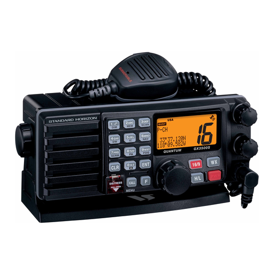
Oversized alphanumeric LCD, knobs and keys
30 W Loud Hailer with listen back and 4 fog horns, Bells & Whistles
Direct keypad entry of a channel using the keypad
Removable ClearVoice speaker microphone with 16/9 key and channel
selection
8
Display shows channel names, and repeats GPS information
Capable of connecting 2 optional enhanced RAM+ second station re-
mote microphones
8
DSC distress call automatically broadcasts lat/long and vessel ID
DSC position request function and NMEA data input/output to connect to
8
GPS Plotter
Versatile user-programmable Scanning, Priority Scan and Dual Watch
One-button access to Channel 16 and 9
8 with GPS attached
GX3500S
Page 1
Vertex Standard Co., Ltd.
Advertisement
Table of Contents

Related Manuals for Standard Horizon 30063X30


Summary of Contents for Standard Horizon 30063X30
- Page 1 FCC ID: K6630063X30 / IC ID: 511B-30063X30 GX3500S 25 Watt VHF/FM ITU Class D DSC Marine Transceiver Owner's Manual Oversized alphanumeric LCD, knobs and keys 30 W Loud Hailer with listen back and 4 fog horns, Bells & Whistles Direct keypad entry of a channel using the keypad...
-
Page 2: Table Of Contents
FCC ID: K6630063X30 / IC ID: 511B-30063X30 TABLE OF CONTENTS GENERAL INFORMATION ..................4 PACKING LIST ......................4 OPTIONS ......................... 4 SAFETY / WARNING INFORMATION ..............5 FCC RADIO LICENSE INFORMATION ..............6 FCC NOTICE ......................7 7 GETTING STARTED ....................8 7.1 ABOUT VHF RADIO .................. - Page 3 FCC ID: K6630063X30 / IC ID: 511B-30063X30 TABLE OF CONTENTS 11.3 DSC DISTRESS CALL ................. 38 11.3.1 Tansmitting a DSC Distress Call ............38 11.3.2 Receiving a DSC Distress Call ............40 11.4 ALL SHIPS CALL ..................40 11.4.1 Transmitting an All Ships Call ............41 11.4.2 Receiving an All Ships Call ...............
-
Page 4: General Information
FCC ID: K6630063X30 / IC ID: 511B-30063X30 1 GENERAL INFORMATION The Vertex Standard GX3500S is a VHF/FM transceiver designed for use in the frequency range of 156.025 to 163.275 MHz. The GX3500S can be oper- ated from 11 to 16 VDC and has a switchable RF output power of 1 watt or 25 watts. -
Page 5: Safety / Warning Information
FCC ID: K6630063X30 / IC ID: 511B-30063X30 4 SAFETY / WARNING INFORMATION This radio is restricted to occupational use, work related operations only where the radio operator must have the knowledge to control the exposure conditions of its passengers and bystanders by maintaining the minimum separation dis- tance of 0.6 m (2 feet). -
Page 6: Fcc Radio License Information
FCC ID: K6630063X30 / IC ID: 511B-30063X30 5 FCC RADIO LICENSE INFORMATION Vertex Standard radios comply with the Federal Communication Commission (FCC) requirements that regulate the Maritime Radio Service. STATION LICENSE An FCC ship station license is no longer required for any vessel traveling in U.S. -
Page 7: Fcc Notice
FCC ID: K6630063X30 / IC ID: 511B-30063X30 6 FCC NOTICE NOTICE Unauthorized changes or modifications to this equipment may void com- pliance with FCC Rules. Any change or modification must be approved in writing by Marine Division of Vertex Standard. -
Page 8: Getting Started
FCC ID: K6630063X30 / IC ID: 511B-30063X30 7 GETTING STARTED 7.1 ABOUT VHF RADIO The radio frequencies used in the VHF marine band lie between 156 and 158 MHz with some shore stations available between 161 and 163 MHz. The ma- rine VHF band provides communications over distances that are essentially “line of sight”... -
Page 9: Coaxial Cable
FCC ID: K6630063X30 / IC ID: 511B-30063X30 7.3 COAXIAL CABLE VHF antennas are connected to the transceiver by means of a coaxial cable – a shielded transmission line. Coaxial cable is specified by it’s diameter and construction. For runs less than 20 feet, RG-58/U, about 1/4 inch in diameter is a good choice. -
Page 10: Installation
FCC ID: K6630063X30 / IC ID: 511B-30063X30 8 INSTALLATION 8.1 LOCATION The radio can be mounted at any angle. Choose a mounting location that: • is far enough from any compass to avoid any deviation in compass read- ing due to the speaker magnet •... -
Page 11: Accessory Cable
FCC ID: K6630063X30 / IC ID: 511B-30063X30 2. Connect the red power wire to a 13.8 VDC ±20% power source. Connect the black power wire to a negative ground. 3. If an optional remote extension speaker is to be used, refer to next section for connections. -
Page 12: Connection Of Gps With Nmea Output
The NMEA supported sentences are: Input: GLL, GGA, RMC and GNS (RMC sentence is recommended) Output: DSC and DSE (DSC sentences to Standard Horizon Plotter for Position Polling) If you have further inquires, please feel free to contact Product Support at: Phone: (800) 767-2450 Email: marinetech@vxstdusa.com... -
Page 13: Changing The Gps Time
FCC ID: K6630063X30 / IC ID: 511B-30063X30 8.6 CHANGING THE GPS TIME From the Factory the GX3500S shows GPS satellite time or UTC time. A time offset is needed to show the local time in your area. 1. Press and hold down the [ CALL ( MENU )] key until Radio Setup “... -
Page 14: Changing The Time Location
FCC ID: K6630063X30 / IC ID: 511B-30063X30 8.7 CHANGING THE TIME LOCATION You may select the time display between local time and UTC (time GPS sends to radio). Time is displayed when GPS position (LAT/LON) is displayed by press- ing the [ F ] key followed by the [ 6 ( NAV )] key. -
Page 15: Changing Cog To True Or Magnetic
FCC ID: K6630063X30 / IC ID: 511B-30063X30 8.8 CHANGING COG TO TRUE OR MAGNETIC Allows customizing the NAV data showing GPS Course Over Ground (COG). Factory default is True however following the steps below the COG can be changed to Magnetic. -
Page 16: Optional Mmb-84 Flush Mount Installation
FCC ID: K6630063X30 / IC ID: 511B-30063X30 8.9 OPTIONAL MMB-84 FLUSH MOUNT INSTALLATION 1. To assist in flush mounting, a template has been included. Use this tem- plate to find the mounting location. 2. Use the template to mark the location where the rectangular hole is to be cut. -
Page 17: Optional Enhanced Ram+ Second Station Mic Installation
FCC ID: K6630063X30 / IC ID: 511B-30063X30 8.10 OPTIONAL ENHANCED RAM+ SECOND STATION MIC INSTALLATION The GX3500S is capable of using up to 2 Enhanced RAM+ mics to remotely control the Radio, DSC and PA/Fog functions. In addition the GX3500S can operate as a full function intercom system. -
Page 18: Controls And Indicators
FCC ID: K6630063X30 / IC ID: 511B-30063X30 9 CONTROLS AND INDICATORS NOTE This section defines each control of the transceiver. See Figure 4 for location of controls. For detailed operating instructions refer to section “10 BASIC OPERATION.” VOLUME CONTROL ( VOL ) Adjusting this control clockwise, increases the audio volume level. - Page 19 FCC ID: K6630063X30 / IC ID: 511B-30063X30 DISTRESS PULL OPEN Figure 4. Controls and Connectors GX3500S Page 19 Vertex Standard Co., Ltd.
- Page 20 FCC ID: K6630063X30 / IC ID: 511B-30063X30 [ PWR ] Key Turns the transceiver on and off. To turn the transceiver on, press and hold this key until the LCD turns on. To turn it off, press and hold this key until the LCD turns off.
- Page 21 FCC ID: K6630063X30 / IC ID: 511B-30063X30 [ 4 ( DW )] Key When in radio mode, this key is used to directly select channel digit “4” in a channel number. Secondary use (Depends on the transceiver version) Press the [ F ] key first then press the [ 4 ( DW )] key, scan for voice commu- nications on the priority channel and another selected channel until a signal is received on either channel (Dual Watch).
- Page 22 FCC ID: K6630063X30 / IC ID: 511B-30063X30 [ 9 ( FOG )] Key When in radio mode, this key is used to directly select channel digit “9” in a channel number. Secondary use Press the [ F ] key first then press the [ 9 ( FOG )] key, available to operate the Fog Horn function.
- Page 23 FCC ID: K6630063X30 / IC ID: 511B-30063X30 [ F ] Key Press the [ F ] key to activate the “Alternate” key function. [ DISTRESS ] Key Used to send a DSC Distress Call. To send the distress call refer to section “11.3.1 (Transmitting A DSC Distress Call).”...
-
Page 24: Basic Operation
FCC ID: K6630063X30 / IC ID: 511B-30063X30 10 BASIC OPERATION 10.1 RECEPTION 1. After the transceiver has been installed, ensure that the power supply and antenna are properly connected. 2. Press and hold the [ PWR ] key until the radio turns on. -
Page 25: Transmit Time-Out Timer (Tot)
FCC ID: K6630063X30 / IC ID: 511B-30063X30 10.3 TRANSMIT TIME - OUT TIMER ( TOT ) When the PTT switch on the microphone is held down, transmit time is limited to 5 minutes. This limits unintentional transmissions due to a stuck microphone. -
Page 26: Noaa Weather Alert Testing
FCC ID: K6630063X30 / IC ID: 511B-30063X30 section “12.9 WX ALERT”), the transceiver is capable of receiving this alert if the following is performed: 1. Program NOAA weather channels into the transceiver’s memory for scan- ning. Follow the same procedure as for regular channels under section “10.12.”... -
Page 27: Calling Another Vessel (Channel 16 Or 9)
FCC ID: K6630063X30 / IC ID: 511B-30063X30 8. Give your vessel’s description: length, design (power or sail), color and other distinguishing marks. The total transmission should not exceed 1 minute. 9. End the message by saying “OVER.” Release the microphone button and listen. -
Page 28: Making Telephone Calls
FCC ID: K6630063X30 / IC ID: 511B-30063X30 10.9 MAKING TELEPHONE CALLS To make a radiotelephone call, use a channel designated for this purpose, The fastest way to learn which channels are used for radiotelephone traffic is to ask at a local marina. Channels available for such traffic are designated Public Correspondence channels on the channel charts in this manual. -
Page 29: Scanning
FCC ID: K6630063X30 / IC ID: 511B-30063X30 10.12 SCANNING Allows the user to select the scan type from Memory scan or Priority scan. “Memory scan” scans the channels that were programmed into memory. “Pri- ority scan” scans the channels programmed in memory with the priority chan- nel. -
Page 30: Priority Scanning P-Scan
10.13 PA/FOG OPERATION PA/FOG mode allows the transceiver to be used as a 30W hailer when an optional STANDARD HORIZON 220SW or 240SW HAIL/PA Horn is installed. When in Hail mode the HAIL/PA Listen’s Back (acts as a microphone and sends sound to the front panel speaker) through the HAIL/PA speaker which provides two-way communications through the HAIL/PA speaker. -
Page 31: Operating The Pa Hail Mode
FCC ID: K6630063X30 / IC ID: 511B-30063X30 10.13.1 Operating the PA HAIL mode 1. Press the [ F ] key followed by the [ 8 ( PA )] key acti- vate the PA HAIL mode. 2. Press the PTT switch to speak through the HAIL/PA speaker. -
Page 32: Lcd Dimmer
FCC ID: K6630063X30 / IC ID: 511B-30063X30 10.15 LCD DIMMER Allows setting up the backlight intensity or to turn it off. 1. Press the [ F ] key followed by the [ 1 ( DIM )] key to en- abling the setting up the backlight intensity. -
Page 33: Communication
FCC ID: K6630063X30 / IC ID: 511B-30063X30 10.16.1 Communication 1. Press the [ F ] key followed by the [ 5 ( IC )] key, the mode is changed to “INTERCOM” mode. 2. If your GX3500S is equipped two RAM+ Mic’s, se- lect the companion you wish to communicate (RAM1, RAM2, or ALL) with the CHANNEL selector knob, then press the [ ENT ] key. -
Page 34: Voice Scrambler
FCC ID: K6630063X30 / IC ID: 511B-30063X30 10.17 VOICE SCRAMBLER If privacy of communications is desired, a CVS2500 voice scrambler (VS) can be installed in the transceiver. Contact your Dealer to have a CVS2500 installed. 1. Press the [ F ] key followed by the [ 7 ( SCRM )] key, the voice scrambler is activated. - Page 35 FCC ID: K6630063X30 / IC ID: 511B-30063X30 MEMO GX3500S Page 35 Vertex Standard Co., Ltd.
-
Page 36: Digital Selective Calling
FCC ID: K6630063X30 / IC ID: 511B-30063X30 11 DIGITAL SELECTIVE CALLING 11.1 GENERAL WARNING This radio is designed to generate a digital maritime distress and safety call to facilitate search and rescue. To be effective as a safety device, this equipment must be used only within communication range of a shore- based VHF marine channel 70 distress and safety watch system. -
Page 37: Maritime Mobile Service Identity (Mmsi)
FCC ID: K6630063X30 / IC ID: 511B-30063X30 11.2 MARITIME MOBILE SERVICE IDENTITY (MMSI) 11.2.1 What is an MMSI? An MMSI is a nine digit number used on Marine Transceivers capable of using Digital Selective Calling (DSC). This number is used like a telephone number to selectively call other vessels. -
Page 38: Dsc Distress Call
FCC ID: K6630063X30 / IC ID: 511B-30063X30 11.3 DSC DISTRESS CALL The GX3500S is capable of transmitting and receiving DSC Distress messages to all DSC radios. The GX3500S may be connected to a GPS to also transmit the Latitude, Longitude of the vessel. - Page 39 FCC ID: K6630063X30 / IC ID: 511B-30063X30 Transmitting a DSC Distress Call with Nature of Distress The GX3500S is capable of transmitting a DSC Distress Call with the following “Nature of Distress” categories: Undesignated, Fire, Flooding, Collision, Grounding, Capsizing, Sinking, Adrift, Abandoning, Piracy, MOB 1.
-
Page 40: Receiving A Dsc Distress Call
FCC ID: K6630063X30 / IC ID: 511B-30063X30 11.3.2 Receiving a DSC Distress Call 1. When a DSC Distress call is received, an emergency alarm sounds. Then channel 16 is automatically selected. 2. Press any key to stop the alarm. 3. Turn the CHANNEL selector knob to change the dis- play to show the position of the vessel in distress. -
Page 41: Transmitting An All Ships Call
FCC ID: K6630063X30 / IC ID: 511B-30063X30 11.4.1 Transmitting an All Ships Call 1. Press the [ CALL ( MENU )] key. The “DSC Operation” menu will appear. 2. Turn the CHANNEL selector knob to select “All Ships.” 3. Press the [ ENT ] key. (To cancel, turn the CHANNEL selector knob to select “Exit.”) -
Page 42: Individual Call
FCC ID: K6630063X30 / IC ID: 511B-30063X30 11.5 INDIVIDUAL CALL This feature allows the GX3500S to contact another vessel with a DSC VHF radio and automatically switch the receiving radio to a desired communications channel. This feature is similar to calling a vessel on CH16 and requesting to go to another channel (switching to the channel is private between the two stations). -
Page 43: Setting Up Individual Ringer
FCC ID: K6630063X30 / IC ID: 511B-30063X30 10. Enter the MMSI number by the keypad. If a mistake was made entering in the number, pressing the [ CLR ] key to delete the wrong character. 11. To store the data entered, press and hold the [ ENT ] key. -
Page 44: Setting Up Individual / Group Call Ringer
FCC ID: K6630063X30 / IC ID: 511B-30063X30 11.5.3 Setting up the Individual/Group Call Ringer When a Individual Call or Group Call is received the radio will produce a ringing tone for 3 minutes. This selection allows the Individual Call ringer time to be changed. -
Page 45: Transmitting An Individual Call
FCC ID: K6630063X30 / IC ID: 511B-30063X30 11.5.4 Transmitting an Individual Call This feature allows the user to contact another vessel with a DSC radio. This feature is similar to calling a vessel on CH16 and requesting to go to another channel. - Page 46 FCC ID: K6630063X30 / IC ID: 511B-30063X30 Manual Calling You may enter an MMSI number manually to contact without the Setting up the Individual Directory. 1. Press the [ CALL ( MENU )] key. The “DSC Operation” menu will appear.
-
Page 47: Receiving An Individual Call
FCC ID: K6630063X30 / IC ID: 511B-30063X30 11.5.5 Receiving an Individual Call When receiving an individual call, an acknowledgment must be sent back to the calling station. The GX3500S default setting is Automatic, but has a selection that allows you to manually send a reply before the radio will switch to the re- quested calling channel. -
Page 48: Group Call
FCC ID: K6630063X30 / IC ID: 511B-30063X30 11.6 GROUP CALL This feature allows the user to contact a group of specific vessels (example members of a yacht club) using DSC radios with Group call function to auto- matically switch to a desired channel for voice communications. -
Page 49: Transmitting A Group Call
FCC ID: K6630063X30 / IC ID: 511B-30063X30 number entry. 10. Enter the MMSI number by the keypad. If a mistake the [ CLR ] was made entering in the number, press key to delete the wrong character. 11. To enter the desired number and move one space to the right press the [ ENT ] key. - Page 50 FCC ID: K6630063X30 / IC ID: 511B-30063X30 Manual Calling You may enter an MMSI number manually to contact without the Setting up the Group call number. 1. Press the [ CALL ( MENU )] key. The “ DSC Operation ”...
-
Page 51: Receiving A Group Call
FCC ID: K6630063X30 / IC ID: 511B-30063X30 11.6.3 Receiving a Group Call 1. When a group call is received, the GX3500S will pro- duce a ringing alarm sound. 2. The radio automatically switches to the requested channel. 3. Press any key to stop the alarm. -
Page 52: Position Request
GX3500S. Standard Horizon has taken this feature one step further, if any Standard Hori- zon GPS is connected to the GX3500S, the polled position of the vessel is shown on the display of the GPS chart plotter making it easy to navigate to the location of the polled vessel. -
Page 53: Transmitting A Position Request To Another Vessel
FCC ID: K6630063X30 / IC ID: 511B-30063X30 The GX3500S has the capability to turn off the Position Request ringer. 1. Press and hold down the [ CALL ( MENU )] key until “Radio Setup” menu appear. 2. Turn the CHANNEL selector knob to select “DSC Setup”... - Page 54 FCC ID: K6630063X30 / IC ID: 511B-30063X30 NOTE If the GX3500S does not receive position data from the polled vessel, the LCD will show “NO POSITION DATA.” Manual Request You may enter an MMSI number manually to contact without the Setting up the Individual / Position Call Directory.
-
Page 55: Receiving A Position Request
FCC ID: K6630063X30 / IC ID: 511B-30063X30 11.7.3 Receiving a Position Request When a position request call is received from another vessel, a ringing alarm will sound and POS REQUEST will be show in the LCD. Operation and trans- ceiver function differs depending on “... -
Page 56: Position Send
FCC ID: K6630063X30 / IC ID: 511B-30063X30 11.8 POSITION SEND The feature is similar to Position Request, however instead of requesting a position of another vessel this function allows you to send your position to an- other vessel. Your vessel must have an operating GPS receiver connected for the GX3500S to send the position. -
Page 57: Transmitting A Dsc Position Send Call
FCC ID: K6630063X30 / IC ID: 511B-30063X30 11.8.2 Transmitting a DSC Position Send Call Pre-Programmable Calling 1. Press the [ CALL ( MENU )] key. The “ DSC Operation ” menu will appear in the display. 2. Turn the CHANNEL selector knob to select the “... - Page 58 2. Press the [ 16/9 ] key to stop ringing 3. The position from the vessel sending it's position will be shown on the dis- play of the radio and also transferred to any Standard Horizon GPS Chart plotter if connected.
-
Page 59: Manual Inputting Of The Gps Location (Lat/Lon)
FCC ID: K6630063X30 / IC ID: 511B-30063X30 11.9 MANUAL INPUTTING OF THE GPS LOCATION ( LAT/LON You may send the Latitude/Longitude of your vessel manually even if the GX3500S is not connected the GPS receiver unit. After the position is entered, transmitting a DSC Distress, Position Request, or Position Send will contain the manually entered position. -
Page 60: Radio Setup Mode
FCC ID: K6630063X30 / IC ID: 511B-30063X30 12 RADIO SETUP NOTE The optional RAM+ MIC CMP25 can also change the RADIO SETUP menu. Refer to page 74 for details. 12.1 LCD CONTRAST This selection sets up the display for best viewabilty for the varying mounting locations (overhead or below). -
Page 61: Time Offset
FCC ID: K6630063X30 / IC ID: 511B-30063X30 12.2 TIME OFFSET This selection sets the time offset between local time and UTC (time GPS sends to radio). Time is displayed when GPS position (LAT/LON) is displayed by pressing the [ F ] key followed by the [ 6 ( NAV )] key. -
Page 62: Time Location
FCC ID: K6630063X30 / IC ID: 511B-30063X30 12.3 TIME LOCATION This selection selects the time display between local time and UTC (time GPS sends to radio). Time is displayed when GPS position (LAT/LON) is displayed by pressing the [ F ] key followed by the [ 6 ( NAV )] key. -
Page 63: Priority Channel Set
FCC ID: K6630063X30 / IC ID: 511B-30063X30 12.5 PRIORITY CHANNEL SET Allows selection the priority channel. 1. Press and hold down the [ CALL ( MENU )] key until “ Radio Setup ” menu appears. 2. Press the [ ENT ] key, then select “... -
Page 64: Scan Resume Time
FCC ID: K6630063X30 / IC ID: 511B-30063X30 12.7 SCAN RESUME TIME This selection is used to select the time the GX3500S waits after a transmis- sion ends before starting scanning. 1. Press and hold down the [ CALL ( MENU )] key until Radio Setup “... -
Page 65: Wx Alert
FCC ID: K6630063X30 / IC ID: 511B-30063X30 12.9 WX ALERT This selection allows the radios NOAA Weather alert to be turned off. Default setting is ON. 1. Press and hold down the [ CALL ( MENU )] key until Radio Setup “... -
Page 66: Channel Name Change
FCC ID: K6630063X30 / IC ID: 511B-30063X30 12.10 CHANNEL NAME CHANGE This selection allows you to customize the name of a channel from the default name. 1. Press and hold down the [ CALL ( MENU )] key until Radio Setup “... -
Page 67: Naming The Radio Or Ram+ Stations
FCC ID: K6630063X30 / IC ID: 511B-30063X30 12.11 NAMING THE RADIO OR RAM+ STATIONS This selection allows you to provide the name to the radio and optional RAM+ Mic’s when connected. 1. Press and hold down the [ CALL ( MENU )] key until Radio Setup “... -
Page 68: Fog Alert Tone Frequency
FCC ID: K6630063X30 / IC ID: 511B-30063X30 12.12 FOG ALERT TONE FREQUENCY This selection allows you to select the Alert Tone Frequency for the PA/FOG Operation. Available selections are “200 Hz” through “850 Hz” in 50 Hz steps. The default Alert Tone Frequency is 400 Hz. -
Page 69: Enhanced Ram+ Mic Opertion
FCC ID: K6630063X30 / IC ID: 511B-30063X30 13 ENHANCED RAM+ MIC OPERATION When the RAM+ microphone is connected to the GX3500S, most VHF, DSC, setup menus and PA modes can be remotely operated. The RAM+ Mic sup- plied with 23 feet (7 m) of routing cable and can be extended up to 70 feet (21 m) using three 23 feet extension cables model CT-100. - Page 70 FCC ID: K6630063X30 / IC ID: 511B-30063X30 POWER SWITCH ( PWR ) Press and hold down this key to turn to the transceiver and RAM+ Mic on and off. PTT ( Push-To-Talk ) SWITCH Activates transmission. [ H/L ] KEY Toggles between high and low power.
- Page 71 FCC ID: K6630063X30 / IC ID: 511B-30063X30 [ DW ] Key Watches for a transmission on CH16 and another selected channel until either signal is received. (Dual watch) Secondary use Press and hold [ DW ] key, intercom operation will operate between radio and RAM+ Mic.
-
Page 72: Intercom Opertion
FCC ID: K6630063X30 / IC ID: 511B-30063X30 RECEIVED ACK: acknowledgment signal is received. RECEIVED RLY: relay signal is received from another vessel or coast station. 8. To cancel the DSC distress alarm signal from the speaker, press any key. 13.2 INTERCOM OPERATION 13.2.1 Communication... -
Page 73: Pa/Fog Operation
FCC ID: K6630063X30 / IC ID: 511B-30063X30 13.3 PA/FOG OPERATION The RAM+ is capable of controlling the 30W Public address, 4 fog horns, bells and whistles. 13.3.1 Operating the PA / Hailer 1. Press and hold the [ NAV ] key then select PA with the [ ] or [ ] key. -
Page 74: Dsc/Radio Setup Mode
FCC ID: K6630063X30 / IC ID: 511B-30063X30 13.4 DSC/RADIO SETUP MODE The RAM+ can access the DSC / RADIO setup menu (refer to section “10 DIGITAL SELECTIVE CALLING” and section “12 RADIO SETUP” for details). LAMP CONTRAST , and KEY BEEP menu item accessed from the RAM+ only controls the RAM+’s display and speaker. -
Page 75: Maintenance
FCC ID: K6630063X30 / IC ID: 511B-30063X30 14 MAINTENANCE The inherent quality of the solid-state components used in this transceiver will provide many years of continuous use. Taking the following precautions will pre- vent damage to the transceiver. • Keep the microphone connected or the jack covered at all times to prevent corrosion of electrical contacts;... -
Page 76: Troubleshooting Chart
FCC ID: K6630063X30 / IC ID: 511B-30063X30 14.3 TROUBLESHOOTING CHART SYMPTOM PROBABLE CAUSE REMEDY Transceiver fails to No DC voltage to the a. Check the 12VDC battery connections and power up. transceiver, or blown the fuse. fuse. b. The PWR key needs to be pressed and held to turn the radio on. -
Page 77: Channel Assignments
FCC ID: K6630063X30 / IC ID: 511B-30063X30 15. CHANNEL ASSIGNMENTS Tables on the following columns list the VHF Marine Channel assignments for U.S.A. and International use. Below are listed some data about the charts. 1. VTS. Where indicated, these channels are part of the U.S. Coast Guard’s Vessel Traffic System. - Page 78 FCC ID: K6630063X30 / IC ID: 511B-30063X30 6. Marine vessels equipped with VHF radios are required to monitor Channel 16. VHF MARINE CHANNEL CHART CHANNEL USE D 156.050 160.650 Public Correspondence (Marine Operator) 156.050 Port Operation and Commercial. VTS in selected areas D 156.100 160.700 Public Correspondence (Marine Operator)
- Page 79 FCC ID: K6630063X30 / IC ID: 511B-30063X30 VHF MARINE CHANNEL CHART CHANNEL USE D 157.150 161.750 Public Correspondence (Marine Operator) 157.150 U.S. Government Only D 157.200 161.800 Public Correspondence (Marine Operator) D 157.250 161.850 Public Correspondence (Marine Operator) D 157.300 161.900 Public Correspondence (Marine Operator) D 157.350 161.950 Public Correspondence (Marine Operator)
- Page 80 FCC ID: K6630063X30 / IC ID: 511B-30063X30 VHF MARINE CHANNEL CHART CHANNEL USE 156.775 Port Operations (Inter-ship only) (1W) 156.825 Port Operations (Inter-ship only) (1W) 156.875 Port Operations (Inter-ship only) (1W) 156.875 Port Operations (Inter-ship only) D 156.925 161.525 Public Correspondence (Marine Operator), Port operation, ship-movement 156.925...
- Page 81 FCC ID: K6630063X30 / IC ID: 511B-30063X30 Points of communica- Points of communica- Carrier frequency Carrier frequency tion Intership and be- tion Intership and be- Channel Channel tween coast and ship tween coast and ship designator designator Coast Coast Ship...
- Page 82 FCC ID: K6630063X30 / IC ID: 511B-30063X30 4: Use of 156.875 MHz is limited to communications with pilots regarding the movement and docking of ships. Normal output power must not exceed 1 watt. 5: 156.375 MHz and 156.650 MHz are available primarily for intership navigational commu- nications.
-
Page 83: Warranty
In the event of a defect, malfunction or failure of the Product during the war- ranty period, STANDARD HORIZON’s liability for any breach of contract or any breach of express or implied warranties in connection with the sale of Products... - Page 84 This warranty only extends to Products sold within the 50 States of the United States of America and the District of Columbia. STANDARD HORIZON will pay all labor to repair the product and replacement parts charges incurred in providing the warranty service except where purchaser abuse or other qualifying exceptions exist.
- Page 85 Product Support Inquiries If you have any questions or comments regarding the use of the GX3500S, you can visit the STANDARD HORIZON Web site to send an E-Mail or contact the Product Support team at (714) 827-7600 ext 6300 M-F 7:00- 5:00PST.
-
Page 86: Specifications
FCC ID: K6630063X30 / IC ID: 511B-30063X30 17 SPECIFICATIONS Performance specifications are nominal, unless otherwise indicated, and are subject to change without notice. 17.1 GENERAL Channels ............. All USA, International and Canadian Input Voltage ..................13.8 VDC ±20% Current Drain Standby ...................... -
Page 87: Appendix
FCC ID: K6630063X30 / IC ID: 511B-30063X30 18 APPENDIX FOG HORN TIMING CHART The fog horn function sounds a horn repeatedly until the function is turned off. TYPE PATTERN USAGE UNDERWAY One 5-second blasts evey 120 seconds. Motor vessel underway and making way. - Page 88 FCC ID: K6630063X30 / IC ID: 511B-30063X30 Copyright 2004 VERTEX STANDARD CO., LTD. Marine Division of VERTEX STANDARD All rights reserved. US Headquarters No portion of this manual 10900 Walker Street, Cypress, CA 90630, U.S.A. may be reproduced www.standardhorizon.com without the permission of VERTEX STANDARD CO., LTD.