Table of Contents
Advertisement
Quick Links
Advertisement
Table of Contents

Related Manuals for GMC Camille Bauer SINEAX AM2000


Summary of Contents for GMC Camille Bauer SINEAX AM2000
- Page 1 20in Bearbeitung Device handbook SINEAX AM2000 Operating Instructions SINEAX AM2000 (2019-06) Camille Bauer Metrawatt AG Aargauerstrasse 7 CH-5610 Wohlen / Switzerland Phone: +41 56 618 21 11 Telefax: +41 56 618 35 35 E-Mail: info@cbmag.com https://www.camillebauer.com...
- Page 2 Legal information Warning notices In this document warning notices are used, which you have to observe to ensure personal safety and to prevent damage to property. Depending on the degree of danger the following symbols are used: If the warning notice is not followed death or severe personal injury will result.
-
Page 3: Table Of Contents
Contents 1. Introduction ..........................5 1.1 Purpose of this document ......................5 1.2 Scope of supply ........................5 1.3 Further documents ........................5 2. Safety notes ..........................6 3. Device overview .......................... 6 3.1 Brief description ........................6 3.2 Available measurement data ....................6 4. - Page 4 7.1 Operating elements ....................... 41 7.2 Selecting the information to display ..................41 7.3 Measurement displays and used symbols ................42 7.4 Resetting measurement data ....................44 7.5 Configuration ........................44 7.5.1 Configuration at the device .................... 44 7.5.2 Configuration via web browser ..................46 7.6 Alarming..........................
-
Page 5: Introduction
1. Introduction 1.1 Purpose of this document This document describes the universal measurement device for heavy-current quantities SINEAX AM2000. It is intended to be used by: • Installation personnel and commissioning engineers • Service and maintenance personnel • Planners Scope This handbook is valid for all hardware versions of the AM2000. -
Page 6: Safety Notes
2. Safety notes Device may only be disposed in a professional manner! The installation and commissioning should only be carried out by trained personnel. Check the following points before commissioning: – that the maximum values for all the connections are not exceeded, see "Technical data" section, –... -
Page 7: Mechanical Mounting
4. Mechanical mounting ► The AM2000 is designed for panel mounting Please ensure that the operating temperature limits are not exceeded when determining the place of mounting (place of measurement). By installing, the device becomes part of an electrical power installation that must be designed, operated and maintained in accordance with country-specific regulations so that the installation is safe and provides prevention against fire and explosion as far as possible. -
Page 8: Electrical Connections
5. Electrical connections Ensure under all circumstances that the leads are free of potential when connecting them! 5.1 General safety notes Please observe that the data on the type plate must be adhered to! The national provisions have to be observed in the installation and material selection of electric lines, e.g. -
Page 9: Terminal Assignments Of The I/O Extensions
5.2 Terminal assignments of the I/O extensions Function Option 1 Option 2 Option 3 Option 4 1.1: 51,52,53 2.1: 61,62,63 4.1: 31,32,33 2 relay outputs 1.2: 55,56,57 2.2: 65,66,67 4.2: 35,36,37 1.1: 56(+), 57(-) 2.1: 66(+), 67(-) 3.1: 46(+), 47(-) 4.1: 36(+), 37(-) 2 analog outputs 1.2: 55(+), 57(-) -
Page 10: Inputs
5.4 Inputs All voltage measurement inputs must originate at circuit breakers or fuses rated 5 Amps or less. This does not apply to the neutral connector. You have to provide a method for manually removing power from the device, such as a clearly labeled circuit breaker or a fused disconnect switch in accordance with IEC 60947-2 or IEC 60947-3. - Page 11 Single-phase AC mains Direct connection Maximum permissible rated voltage 300V to ground! (UL listed) With current transformer (UL listed) With current and voltage transformer (UL listed) PM 1000087 000 12 Device handbook SINEAX AM2000 11/91...
- Page 12 Three wire system, balanced load, current measurement via L1 Direct connection Maximum permissible rated voltage 300V to ground (520V ph-ph)! (UL listed) With current transformer (UL listed) With current and voltage transformers (UL listed) In case of current measurement via L2 or L3 connect the device according to the following table: Terminals I2(k)
- Page 13 Four wire system, balanced load, current measurement via L1 Direct connection Maximum permissible rated voltage 300V to ground! (UL listed) With current transformer (UL listed) With current and voltage transformer (UL listed) In case of current measurement via L2 or L3 connect the device according to the following table: Terminals I2(k)
- Page 14 Three wire system, unbalanced load Direct connection Maximum permissible rated voltage 300V to ground (520V ph-ph)! (UL listed) With current transformers (UL listed) With current and 3 single-pole isolated voltage transformers (UL listed) PM 1000087 000 12 Device handbook SINEAX AM2000 14/91...
- Page 15 Three wire system, unbalanced load, Aron connection Direct connection Maximum permissible rated voltage 300V to ground (520V ph-ph)! (UL listed) With current transformers (UL listed) With current and 3 single-pole isolated voltage transformers (UL listed) PM 1000087 000 12 Device handbook SINEAX AM2000 15/91...
- Page 16 Four wire system, unbalanced load Direct connection Maximum permissible rated voltage 300V to ground (520V ph-ph)! (UL listed) With current transformer (UL listed) With current and 3 single-pole isolated voltage transformers (UL listed) PM 1000087 000 12 Device handbook SINEAX AM2000 16/91...
- Page 17 Four wire system, unbalanced load, Open-Y Direct connection Maximum permissible rated voltage 300V to ground (520V ph-ph)! (UL listed) With current transformers (UL listed) With current and 2 single-pole isolated voltage transformers (UL listed) PM 1000087 000 12 Device handbook SINEAX AM2000 17/91...
- Page 18 Split-phase ("two phase system"), unbalanced load Direct connection Maximum permissible rated voltage 300V to ground (600V ph-ph)! (UL listed) With current transformers (UL listed) With current and voltage transformer In systems without a primary neutral conductor a voltage transformer with a secondary center tap can also be used.
-
Page 19: Power Supply
5.5 Power supply A marked and easily accessible current limiting switch in accordance with IEC 60947-2 has to be arranged in the vicinity of the device for turning off the power supply. Fusing should be 10 Amps or less and must be rated for the available voltage and fault current. 5.6 Relays When the device is switched off the relay contacts are de-energized, but dangerous voltages may be present. -
Page 20: Digital Outputs
Active inputs (no external power supply required) Example with meter pulse and status inputs Technical data acc. EN62053-31, class B Open circuit voltage ≤ 15 V Short circuit current < 15 mA Current at R =800Ω ≥ 2 mA 5.8 Digital outputs The device has two standard digital outputs for which an external 12 / 24 VDC power supply is required. -
Page 21: Analog Outputs
5.9 Analog outputs Analog outputs are available for devices with corresponding I/O extensions only. See nameplate. Analog outputs may be remote controlled. Connection to an analog input card of a PLC or a control system The device is an isolated measurement device. The module outputs are galvanically connected, but the modules isolated from each other. -
Page 22: Fault Current Detection
5.11 Fault current detection Each fault current module provides two channels for monitoring differential or fault currents in earthed AC current systems. In any case, measurement has to be performed via suitable current transformers, a direct measurement is not possible. The module is not suited for monitoring operating currents of normally live conductors (L1, L2, L3, N). - Page 23 Example: Fault current monitoring in a TNS system Hints (1) If the current transformers for the fault current detection needs to be grounded on the secondary side this has to be done via the COM connector. (2) Note that all conductors have to pass through the opening of the residual current transformer in the same direction.
-
Page 24: Temperature Inputs
5.12 Temperature inputs Each temperature module provides two channels for temperature monitoring. They can be used in two ways: a) Temperature measurement via Pt100 sensor • Measurement range: -50 up to 250°C • 2 configurable alarm limits • Configurable alarm delay time for ON / OFF •... -
Page 25: Gps Time Synchronization
5.13 GPS time synchronization The optional GPS connection module serves for connecting a GPS receiver as a very accurate time synchronization source for the measurement device. The GPS receiver, available as an accessory, is used as outdoor antenna to process data from multiple GPS satellites simultaneously. GPS receiver Only use the receiver Garmin GPS 16x-LVS (article no. - Page 26 Connecting the GPS receiver Never connect the RJ45 connector of the connecting cable directly to a network device such as a router or switch. These devices could be damaged. The GPS receiver is plugged directly into the GPS connection module. The connection cable has a length of 5 m.
-
Page 27: Commissioning
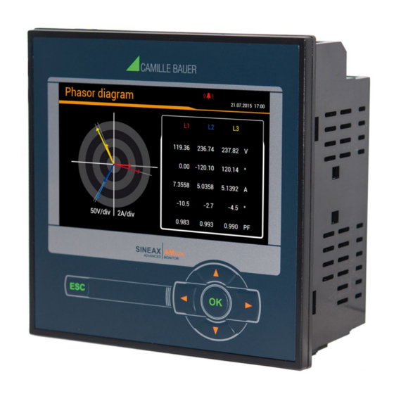
6. Commissioning Before commissioning you have to check if the connection data of the device match the data of the plant (see nameplate). If so, you can start to put the device into operation by switching on the power supply and the measurement inputs. - Page 28 b) Phasor verification: The phasor diagram shows a technical visualization of the current and voltage phasors, using a counter-clockwise rotation, independent of the real sense of rotation. The diagram is always built basing on the voltage of the reference channel (direction 3 o’clock) Correct installation (expectation) •...
-
Page 29: Ethernet Installation
Ethernet installation 6.3.1 Settings Before devices can be connected to an existing Ethernet network, you have to ensure that they will not disturb the normal network service. The rule is: None of the devices to connect is allowed to have the same IP address than another device already installed The device can be equipped with multiple Ethernet interfaces whose network settings can be configured independently. - Page 30 For a direct communication between device and PC both devices need to be in the same network when the subnet mask is applied: Example 1 decimal binary 11000000 10101000 00000001 01100101 192.168. 1.101 IP address 11111111 11111111 11111111 11100000 255.255.255.224 Subnet mask xxxxx variable range...
-
Page 31: Connection Of The Standard Interface
Time synchronization via NTP protocol For the time synchronization of devices via Ethernet NTP (Network Time Protocol) is the standard. Corresponding time servers are used in computer networks, but are also available for free via Internet. Using NTP it's possible to hold all devices on a common time base. Two different NTP servers may be defined. -
Page 32: Connection Of The Iec61850 Interface
6.3.3 Connection of the IEC61850 interface The RJ45 sockets X1 and X2 serve for direct connecting Ethernet cables. Both ports are equivalent and internally connected via a switch. Interface: RJ45 sockets, Ethernet 100BaseTX Mode: 10/100 MBit/s, full / half duplex, Auto-negotiation ... -
Page 33: Mac Addresses
6.3.5 MAC addresses For uniquely identifying Ethernet connections in a network, a unique MAC address is assigned to each connection. Compared to the IP address, which may be modified by the user at any time, the MAC address is static. Standard Ethernet interface IEC61850 Ethernet interface PROFINET Ethernet interface... -
Page 34: Iec 61850 Interface
6.4 IEC 61850 interface The features of the IEC61850 interface are described in a separate document: >> IEC61850 interface SINEAX AMx000/DM5000, LINAX PQx000, CENTRAX CUx000 This document is available via: >> https://www.camillebauer.com/am2000-en 6.5 PROFINET IO interface The PROFINET interface provides a cyclical process image, which can be freely assembled by the user. 6.5.1 General stations description file (GSD) The GSD file describes the functionality available via the PROFINET interface of the device. -
Page 35: Parameterization Of The Device
Before a device can be used in a project, the associated GSD file must be imported in the configuration tool (e.g. TIA Portal). 6.5.2 Parameterization of the device As soon as the GSD file has been imported, the device is available in the hardware catalog and can be integrated using drag&drop. - Page 36 Further steps during parameterization are: • Assigning a unique device name via DCP protocol • Assigning an IP address to the device, normally an automatic procedure • Assembly of the cyclical process image (see below), maximum of 62 measurements • Integration in the topology of the complete system Because these steps are device independent and do rely on the used tool only, further details are not given here.
-
Page 37: Validity Of Measurements
6.5.3 Validity of measurements The following measurements can be used in the process image: • Instantaneous values of voltages, currents, active/reactive/apparent power, frequency, load factor • THD voltages and currents, TDD currents • Odd harmonics of voltages and currents up to the 25 •... -
Page 38: Simulation Of Analog / Digital Outputs
6.6 Simulation of analog / digital outputs To check if subsequent circuits will work properly with output values provided by the device, using the service menu Simulation all analog or digital / relay outputs may be simulated. This is done by either entering analog output values or selecting discrete states for the digital outputs / relays. -
Page 39: Secure Communication Using Https
6.7.2 Secure communication using HTTPS HTTPS provides encrypted communication using TLS (Transport Layer Security). Such as bidirectional encryption of communications between a client and server protects against eavesdropping and tampering of the communication. HTTPS creates a secure channel over an insecure network. Before HTTPS communication can be used a root certificate needs to be installed. -
Page 40: Whitelisting Clients
Agree to install the certificate when the below security warning appears: Customer certificate Upload your certificate and private key via the Settings of the Security system in the item Web Security. 6.7.3 Whitelisting clients It is possible to define an IP address list of up to 10 clients allowed to have access to the device. -
Page 41: Operating The Device
7. Operating the device 7.1 Operating elements Operation is performed by means of 6 keys: navigation 4 keys for ( , , , ) and for the selection of values OK for selection or confirmation menu display, terminate or ... -
Page 42: Measurement Displays And Used Symbols
7.3 Measurement displays and used symbols For displaying measurement information the device uses both numerical and numerical-graphical measurement displays. Examples Measurement information 2 measured quantities 4 measured quantities 2x4 measured quantities 2x4 measured quantities with min/max Graphical measurement display Further examples PM 1000087 000 12 Device handbook SINEAX AM2000 42/91... - Page 43 Incoming / outgoing / inductive / capacitive The device provides information for all four quadrants. Quadrants are normally identified using the roman numbers I, II, III and IV, as shown in the adjacent graphic. Depending on whether the system is viewed from the producer or consumer side, the interpretation of the quadrants is changing: The energy built from the active power in the quadrants I+IV can either been seen as delivered or consumed active energy.
-
Page 44: Resetting Measurement Data
7.4 Resetting measurement data • Minimum and maximum may be reset during operation. The reset may be performed in groups using the service menu. Group Values to be reset Min/max values of voltages, currents and frequency Min/max values of Power quantities (P,Q,Q(H1),D,S); min. load factors Min/max values of power mean-values, bimetal slave pointers and free selectable mean-values Maximum values of harmonic analysis: THD U/I, TDD I, individual harmonics U/I All imbalance maximum values of voltage and current... - Page 45 • Fault current: Configuration of the fault current channels, especially alarm and pre-warning limits, transformer ratios as well as response and dropout delay • Temperature: Configuration of the temperature monitoring channels, especially event text, alarm limits, response and dropout delay, lead resistance •...
-
Page 46: Configuration Via Web Browser
7.5.2 Configuration via web browser It’s recommended to use either Google-Chrome or Firefox as browser. Internet Explorer works with limitations only (partly missing texts, firmware update not possible) For configuration via web browser use the device homepage via http://<ip_addr>. The default IP address of the device is 192.168.1.101. - Page 47 Loading / saving configuration files The user can save the present device configuration on a storage media and reload it from there. The storage or load procedure varies depending on the used browser. Loading a configuration file from a storage media The configuration data of the selected file will be directly loaded into the device.
-
Page 48: Alarming
7.6 Alarming The alarming concept is very flexible. Depending on the user requirements simple or more advanced monitoring tasks may be realized. The most important objects are limit values on base quantities, the monitoring of fault-current, monitoring functions and the summary alarm. 7.6.1 Limit values on base quantities Using limit values either the exceeding of a given value (upper limit) or the fall below a given value... -
Page 49: Monitoring Fault-Currents
7.6.2 Monitoring fault-currents Each (optional) fault current module provides two channels for monitoring residual or fault current. For each of the channels an alarm and a pre-warning limit can be defined, which can be used as follows: … Activating a summary alarm when the alarm limit is violated or a breakage occurs (2mA input only) …... -
Page 50: Temperature Monitoring
7.6.3 Temperature monitoring Each (optional) temperature module provides two channels for temperature monitoring. Used for Pt100 measurement • Up to 2 limit values • Short circuit and wire / sensor breakage monitoring Used for PTC monitoring • Monitoring the PTC response temperature •... -
Page 51: Monitoring Functions
7.6.4 Monitoring functions By means of monitoring functions the user can define an extended condition monitoring, e.g. for triggering an over-current alarm, if one of the phase currents exceeds a certain limit value. The states of all monitoring functions …will be shown in the alarm list (“Alarms” via main menu) …build a summary alarm state Logic inputs Up to three states of limit values, fault-current or temperature monitoring, logic inputs or other monitoring... -
Page 52: Summary Alarm
7.6.5 Summary alarm The summary alarm combines the states of all monitoring function MFx to a superior alarm-state of the overall unit. For each monitoring function you may select if it is used for building the summary alarm state. If at least one of the used functions is in the alarm state, the summary alarm is also in the alarm state. If an optional failure-current monitoring is present, the detection of an alarm state or a breakage of the measurement line (2mA inputs only) activates directly the summary alarm. -
Page 53: Data Recording
7.7 Data recording The optional data logger provides long-term recordings of measurement progressions and events. The recording is performed in endless mode (oldest data will be deleted, as soon as the associated memory is full). Depending on the version ordered, the following data groups are available: Group Data type Request... - Page 54 The selection of the mean-value quantity to display can be performed via choosing the corresponding register. Three different kind of displays are supported: • Daily profile: Hourly mean-values will be shown, independently of the real averaging time • Weekly profile •...
- Page 55 Displaying the chronology of meter contents The chronology of meters is available via the menu Energy and is divided in two groups: • Pre-defined meters • User-defined meters From the difference of two successive meter readings the energy consumption for the dedicated time range can be determined.
-
Page 56: Events
Data export as CSV file the time range of the data to export can be selected. A CSV (Comma separated value) file will be generated. This can be imported as a text file to Excel, with comma as a separator. The same file contains data for all quantities of the respective group. -
Page 57: Micro Sd Card
7.7.3 Micro SD card Devices with data logger are supplied with a micro SD-Card, which provides long recording times. Activity The red LED located next to the SD card signals the logger activity. When data is written to the SD card the LED becomes shortly dark. -
Page 58: Timeouts
7.8 Timeouts The device is designed to display measurements. So, any other procedure will be terminated after a certain time without user interaction and the last active measurement image will be shown again. Menu timeout A menu timeout takes effect after 2 min. without changing the present menu selection. It doesn’t matter if the currently displayed menu is the main menu or a sub-menu: The menu is closed and the last active measurement image is displayed again. -
Page 59: Service, Maintenance And Disposal
8. Service, maintenance and disposal 8.1 Calibration and new adjustment Each device is adjusted and checked before delivery. The condition as supplied to the customer is measured and stored in electronic form. The uncertainty of measurement devices may be altered during normal operation if, for example, the specified ambient conditions are not met. -
Page 60: Technical Data
9. Technical data Inputs Nominal current: adjustable 1...5 A; max. 7.5 A (sinusoidal) Measurement category: 300V CAT III Consumption: ≤ I x 0.01 Ω per phase Overload capacity: 10 A continuous 100 A, 5 x 1 s, interval 300 s Nominal voltage: 57.7…400 V (UL: 347V... - Page 61 Zero suppression, range limitations The measurement of specific quantities is related to a pre-condition which must be fulfilled, that the corresponding value can be determined and sent via interface or displayed. If this condition is not fulfilled, a default value is used for the measurement. Quantity Condition Default...
- Page 62 Relays via plug-in terminals Contact: changeover contact Load capacity: 250 V AC, 2 A, 500 VA 30 V DC, 2 A, 60 W Passive digital inputs via plug-in terminals Nominal voltage 12 / 24 V DC (30 V max.) Input current <...
- Page 63 Temperature inputs via plug-in terminals Number of channels: Measurement current: <1.0mA Connection: 2-wire Input protection: Voltage limitation via protective diode Used for Pt100 measurent Measurement range: -50 up to 250°C / -58 up to 482°F Uncertainty: ±1.0 % of measurement ±1 K Connection monitoring: Short-circuit (<20 Ω), wire / sensor breakage (>1000 Ω) Alarm limits:...
- Page 64 Ambient conditions, general information Operating temperature: –10 up to 15 up to 30 up to + 55°C Storage temperature: –25 up to + 70°C Temperature influence: 0.5 x measurement uncertainty per 10 K Long term drift: 0.5 x measurement uncertainty per year Others: Usage group II (EN 60 688) Relative humidity:...
- Page 65 Safety The current inputs are galvanically isolated from each other Protection class: II (protective insulation, voltage inputs via protective impedance) Pollution degree: Protection: Front: IP40, IP54 (with sealing joint); Housing: IP30; Terminals: IP20 IP54 remark Sealing joint must be applied on the entire circumference of the housing;...
- Page 66 Applied regulations, standards and directives IEC/EN 61 010-1 Safety regulations for electrical measuring, control and laboratory equipment IEC/EN 61000-4-7 General guide on harmonics and interharmonics measurements IEC/EN 60688 Electrical measuring transducers for converting AC electrical variables into analog or digital signals DIN 40110 AC quantities IEC/EN 60068-2-1/...
-
Page 67: Dimensional Drawings
10. Dimensional drawings All dimensions in [mm] PM 1000087 000 12 Device handbook SINEAX AM2000 67/91... -
Page 68: Annex
Annex A Description of measured quantities Used abbreviations Single phase system Split phase; system with 2 phases and center tap 3-wire system with balanced load 3-wire system with unbalanced load 3Lu.A 3-wire system with unbalanced load, Aron connection (only 2 currents connected) 4-wire system with balanced load 4-wire system with unbalanced load 4Lu.O... - Page 69 Measurement Apparent power S ● ● √ √ √ √ √ √ √ √ √ Apparent power S1 ● ● √ √ √ ● ● √ √ √ Apparent power S2 ● ● √ √ Apparent power S3 Fundamental apparent power S(H1) ●...
- Page 70 Reactive power Most of the loads consume a combination of ohmic and inductive current from the power system. Reactive power arises by means of the inductive load. But the number of non-linear loads, such as RPM regulated drives, rectifiers, thyristor controlled systems or fluorescent lamps, is increasing. They cause non- sinusoidal AC currents, which may be represented as a sum of harmonics.
- Page 71 Zero displacement voltage U Starting from the generating system with star point E (which is normally earthed), the star point (N) on load side is shifted in case of unbalanced load. The zero displacement voltage between E und N may be determined by a vectorial addition of the voltage vectors of the three phases: = - (U...
-
Page 72: A2 Harmonic Analysis
A2 Harmonic analysis The harmonic analysis is performed according IEC 61000-4-7 over 10 cycles at 50Hz or 12 cycles at 60Hz. If a measured quantity is available depends on the selected system. Measurement ● ● √ √ √ √ √ THD Voltage U1N/U THD Voltage U2N ●... -
Page 73: A3 System Imbalance
A3 System imbalance Measured quantity UR1: Positive sequence [V] ● √ √ √ √ ● √ √ √ √ UR2: Negative sequence [V] ● √ U0: Zero sequence [V] U: Imbalance UR2/UR1 ● ● √ √ √ √ U: Imbalance U0/UR1 ●... -
Page 74: A4 Mean Values And Trend
A4 Mean values and trend Measured quantity ● ● ● ● Active power I+IV 10s...60min. ● ● ● ● Active power II+III 10s...60min. Reactive power I+II 10s...60min. ● ● ● ● Reactive power III+IV 10s...60min. ● ● ● ● ● ●... -
Page 75: A5 Meters
A5 Meters Measured quantity Active energy I+IV, high tariff ● ● ● ● ● ● ● ● Active energy II+III, high tariff ● ● ● ● ● ● ● ● ● ● ● ● ● ● ● ● Reactive energy I+II, high tariff ●... -
Page 76: B Display Matrices
B Display matrices B0 Used abbreviations for the measurements Instantaneous values Name Measurement identification Unit Description Voltage system TRMS Voltage between phase L1 and neutral TRMS Voltage between phase L2 and neutral TRMS Voltage between phase L3 and neutral TRMS Voltage between phases L1 and L2 TRMS Voltage between phases L2 and L3... - Page 77 Minimum and maximum of instantaneous values Name Measurement identification Unit Description U_MM Minimum and maximum value of U TRMS U1N_MM Minimum and maximum value of U1N TRMS U2N_MM Minimum and maximum value of U2N TRMS Minimum and maximum value of U3N U3N_MM TRMS U12_MM...
- Page 78 Mean-values, trend and bimetal current Name Measurement identification Unit Description (t2) (mu) Mean-value 1 (t2) (mu) Mean-value 2 …. (t2) (mu) …. (t2) (mu) Mean-value 11 (t2) (mu) Mean-value 12 (t2) (mu) TR_M1 Trend mean-value 1 (t2) (mu) TR_M2 Trend mean-value 2 (t2) (mu) ….
- Page 79 Graphical measurement displays Name Presentation Description Graphic of the power triangle consisting of: • Active, reactive and apparent power Px, Qx, Sx • Distortion reactive power Dx Px_TRIANGLE • Fundamental reactive power Qx(H1) • cos(φ) of fundamental • Active power factor PFx PF_MIN Graphic: Minimum active power factor PF in all 4 quadrants Cφ_MIN...
- Page 80 Graphic: Odd harmonics 3 up to 49 + Total Harmonic HO_IX Distortion of all currents Graphic: Odd harmonics 3 up to 49 + Total Harmonic HO_UX (as HO_IX) Distortion of all voltages Graphic: Even harmonics 2 up to 50 + Total Harmonic HE_IX (as HO_IX) Distortion of all currents...
-
Page 81: B1 Display Matrices For Single Phase System
B1 Display matrices for single phase system Display menu Corresponding matrix U_MM I_MAX P_MAX F_MM P_MAX Q_MAX S_MAX P_TRIANGLE PF_MIN Cφ_MIN I> 1.1 / 1.2 I> 2.1 / 2.2 I> 3.1 / 3.2 I> 4.1 / 4.2 ϑ 1.1 / 1.2 ϑ... -
Page 82: B2 Display Matrices For Split-Phase (Two-Phase) Systems
B2 Display matrices for split-phase (two-phase) systems Display menu Corresponding matrix U1N_MM U2N_MM U_MM F_MM I1_MAX I2_MAX P_MAX / P1_MAX Q_MAX / P2_MAX S_MAX / Q1_MAX / Q2_MAX P_TRIANGLE P1_TRIANGLE P2_TRIANGLE PF_MIN Cφ_MIN I> 1.1 / 1.2 I> 2.1 / 2.2 I>... -
Page 83: B3 Display Matrices For 3-Wire System, Balanced Load
B3 Display matrices for 3-wire system, balanced load Display menu Corresponding matrix U12_MM U23_MM U31_MM UR2R1 F_MM UR21_MAX I_MAX P_MAX Q_MAX S_MAX P_TRIANGLE PF_MIN Cφ_MIN I> 1.1 / 1.2 I> 2.1 / 2.2 I> 3.1 / 3.2 I> 4.1 / 4.2 ϑ... -
Page 84: B4 Display Matrices For 3-Wire Systems, Unbalanced Load
B4 Display matrices for 3-wire systems, unbalanced load Display menu Corresponding matrix U12_MM U23_MM U31_MM UR2R1 F_MM UR21_MAX I1_MAX I2_MAX I3_MAX IR2R1 IR21_MAX P_MAX Q_MAX S_MAX P_TRIANGLE PF_MIN Cφ_MIN I> 1.1 / 1.2 I> 2.1 / 2.2 I> 3.1 / 3.2 I>... -
Page 85: B5 Display Matrices For 3-Wire Systems, Unbalanced Load, Aron
B5 Display matrices for 3-wire systems, unbalanced load, Aron Display menu Corresponding matrix U12_MM U23_MM U31_MM UR2R1 F_MM UR21_MAX I1_MAX I2_MAX I3_MAX P_MAX Q_MAX S_MAX P_TRIANGLE PF_MIN Cφ_MIN I> 1.1 / 1.2 I> 2.1 / 2.2 I> 3.1 / 3.2 I>... -
Page 86: B6 Display Matrices For 4-Wire System, Balanced Load
B6 Display matrices for 4-wire system, balanced load Display menu Corresponding matrix U_MM I_MAX P_MAX F_MM P_MAX Q_MAX S_MAX P_TRIANGLE PF_MIN Cφ_MIN I> 1.1 / 1.2 I> 2.1 / 2.2 I> 3.1 / 3.2 I> 4.1 / 4.2 ϑ 1.1 / 1.2 ϑ... -
Page 87: B7 Display Matrices For 4-Wire Systems, Unbalanced Load
B7 Display matrices for 4-wire systems, unbalanced load Display menu Corresponding matrix U1N_MM / U12_MM U2N_MM / U23_MM U3N_MM / U31_MM F_MM / UR2_MM UNB_UR2_UR1 I1_MAX I2_MAX I3_MAX IN_MAX UNB_IR2_IR1 P1_MAX Q1_MAX S1_MAX P2_MAX Q2_MAX S2_MAX P3_MAX Q3_MAX S3_MAX P_MAX Q_MAX S_MAX P_TRIANGLE... -
Page 88: B8 Display Matrices For 4-Wire System, Unbalanced Load, Open-Y
B8 Display matrices for 4-wire system, unbalanced load, Open-Y Display menu Corresponding matrix U1N_MM / U12_MM U2N_MM / U23_MM U3N_MM / U31_MM F_MM I1_MAX I2_MAX I3_MAX IN_MAX UNB_IR2_IR1 P1_MAX Q1_MAX S1_MAX P2_MAX Q2_MAX S2_MAX P3_MAX Q3_MAX S3_MAX P_MAX Q_MAX S_MAX P_TRIANGLE P1_TRIANGLE P2_TRIANGLE... -
Page 89: C Logic Functions
C Logic functions The principal function of the logical gates is given in the following table, for simplicity shown for gates with two inputs only. older symbols function symbol truth table plain text ANSI 91-1984 DIN 40700 (alt) Function is true if all input conditions are fulfilled Function is true if at least one of the input... -
Page 90: D Fcc Statement
D FCC statement The following statement applies to the products covered in this manual, unless otherwise specified herein. The statement for other products will appear in the accompanying documentation. NOTE: This equipment has been tested and found to comply with the limits for a Class A digital device, pursuant to Part 15 of the FCC Rules and meets all requirements of the Canadian Interference-Causing Equipment Standard ICES-003 for digital apparatus. -
Page 91: Index
INDEX Alarming ................ 48 Measured quantities ............68 Basic measurements ..........68 Bimetal current ............74 earth fault monitoring ..........71 Commissioning .............. 27 harmonic analysis ............. 72 Configuration Load factors .............. 70 menu ................ 44 mean values and trend ..........74 cosφ...