Table of Contents
Advertisement
Quick Links
This user's guide describes the characteristics, operation, and use of the TSC4270 evaluation module
(EVM). The TSC4270EVM is an evaluation fixture for the TSC4270, a touch screen controller (TSC) for
capacitive touch panels. A complete circuit description, schematic diagram, and bill of materials are
included.
The following related documents are available for download through the Texas Instruments web site at
http://www.ti.com.
Device
TSC4270
LM3S3748
LM4F120
Windows, Windows XP, Windows 7 are registered trademarks of Microsoft Corporation.
SPI is a trademark of Motorola, Inc.
2
I
C is a trademark of NXP Semiconductors.
All other trademarks are the property of their respective owners.
SBAU208 – April 2013
Submit Documentation Feedback
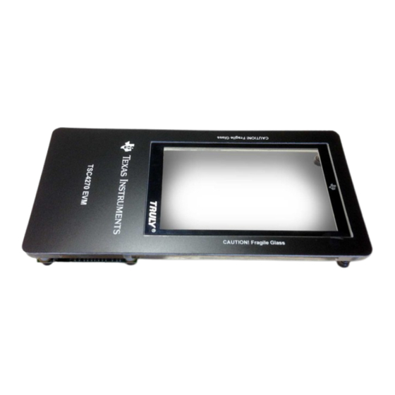
TSC4270 Evaluation Module
Figure 1. TSC4270 Evaluation Module
Table 1. EVM-Related Device Data Sheets
Data sheet available on request
See
LM3S3748
See
LM4F120
Copyright © 2013, Texas Instruments Incorporated
Literature Number
for the latest documentation
for the latest documentation
TSC4270 Evaluation Module
User's Guide
SBAU208 – April 2013
1
Advertisement
Table of Contents

Related Manuals for Texas Instruments TSC4270


Summary of Contents for Texas Instruments TSC4270
-
Page 1: Tsc4270 Evaluation Module
This user's guide describes the characteristics, operation, and use of the TSC4270 evaluation module (EVM). The TSC4270EVM is an evaluation fixture for the TSC4270, a touch screen controller (TSC) for capacitive touch panels. A complete circuit description, schematic diagram, and bill of materials are included. -
Page 2: Table Of Contents
......................Bill of Materials ......................... Schematics List of Figures ....................TSC4270 Evaluation Module ..................TSC4270 DUT Board, Top View ..................TSC4270 DUT Board, Bottom View ....................... Stellaris Motherboard .............. Highlighted Application USB Port on the TSC4270EVM ....................Inf-Wizard Startup Window .................... -
Page 3: Evm Overview
The TSC4270EVM can assist in the process of system prototyping, and firmware and software development around the TSC4270 device. The EVM allows for easy access to the TSC4270 with a user-specified host processor and software in order to direct evaluation on the TSC4270 performance and operating characteristics. The EVM is a... -
Page 4: Hardware Overview
Hardware Overview Analog Interface The TSC4270 supports a 33-wire capacitive touch screen. A 36-pin FPC/FFC connector J1 (part number FH12-36S-0.5SH) is installed on the TSC4270EVM daughterboard, and provides a direct connection to a corresponding 36-pin flat cable from the capacitive touch screen. -
Page 5: Tsc4270 Dut Board, Top View
Digital Interface The TSC4270 EVM is designed to easily interface with multiple control platforms. A convenient 24-pin socket J2 (Samtec SSM-124-X-SV) is installed on the TSC4270EVM daughterboard, and provides an interface to digital signals between the TSC4270 device and the Stellaris LM3S3748 microprocessor on the TSC4270EVM motherboard. -
Page 6: Tsc4270 Dut Board, Bottom View
Hardware Overview www.ti.com Figure 3. TSC4270 DUT Board, Bottom View Figure 4. Stellaris Motherboard TSC4270 Evaluation Module SBAU208 – April 2013 Submit Documentation Feedback Copyright © 2013, Texas Instruments Incorporated... -
Page 7: Power Supply
U5. These regulators generate +3.3 VDC to provide power supplies to the Stellaris microprocessors and other circuitry on the TSC4270EVM motherboard, and also generate +3.3 VDC and +1.8 VDC to provide power-supplies to the TSC4270 on the TSC4270EVM daughterboard. As shown in Table 3, the +3.3 VDC and +1.8 VDC power supplies are provided to the TSC4270EVM... -
Page 8: Highlighted Application Usb Port On The Tsc4270Evm
(a) Plug the USB mini 5-wire cable from the PC to the application USB port shown in Figure Figure 5. Highlighted Application USB Port on the TSC4270EVM (b) Ignore or cancel the Windows automatic driver installation. (c) Navigate to TSC4270\TSC4270_Depends\libusb-win32-bin-1.2.6.0\bin in the unzipped folder. (d) Run inf-wizard.exe. (e) Click Next, as shown in Figure 6 Figure 6. -
Page 9: Inf-Wizard Device Selection
(f) Select the TSC device with Vendor ID = 0x1CBE, and Product ID = 0x0003, and click Next, as shown in Figure 7 Figure 7. Inf-Wizard Device Selection (g) Click Next, as shown in Figure Figure 8. Inf-Wizard Device Configuration SBAU208 – April 2013 TSC4270 Evaluation Module Submit Documentation Feedback Copyright © 2013, Texas Instruments Incorporated... -
Page 10: Inf-Wizard File Save Prompt
10. After installation, unplug the device, and then plug it back in. Figure 10. Inf-Wizard Installation Prompt (j) If the window shown in Figure 11 appears, click Install this driver software anyway. TSC4270 Evaluation Module SBAU208 – April 2013 Submit Documentation Feedback Copyright © 2013, Texas Instruments Incorporated... -
Page 11: Driver Installer Authentication
TSC device is visible in the tree. 5. Plug in the EVM and run the TSC 4270 EVM Application.exe file from the project folder. SBAU208 – April 2013 TSC4270 Evaluation Module Submit Documentation Feedback Copyright © 2013, Texas Instruments Incorporated... -
Page 12: Operation
TSC4270EVM motherboard light up, and the +3.3 V and +1.8 V LEDs on the daughterboard also light After the TSC4270EVM is powered on, launch the TSC4270 EVM Application.exe file. The software should automatically find the TSC4270EVM, and the GUI startup screen appears, as shown in Figure Figure 12. -
Page 13: Gui Block Description
After plugging the EVM into a USB port and starting the TSC4270EVM-PDK software, the GUI is displayed, as shown in Figure 12. Use the TSC4270EVM GUI to test different functions of the TSC4270. There are five main tabs in the GUI: 1. Touch Report 2. -
Page 14: Button Menu
Figure 13. A window pops up asking for the Service Key provided by Texas Instruments. The keyboard shortcut is Ctrl+U. 2. Download flash parameters to TSC: This item downloads the current tunable flash parameters from the tunable flash parameters grid to the TSC. A window pops up asking for the service key provided by Texas Instruments. -
Page 15: Runtime Configuration Grid, Expanded View
TSC4270. Permitted operations include changing the report rate and turning the filters on or off. This operation does not require service or ISP keys. After changing the values, the TSC4270 must be updated with the current settings from the grid by clicking button ii shown in Figure 14. -
Page 16: Tunable Flash Parameters Grid, Expanded View
5.2.3.2 Tunable Flash Parameters Grid Use the tunable flash parameters grid to adjust the flash parameters of the TSC4270. Changing the tunable flash parameters grid affects the behavior of the TSC4270. Uploading flash parameters requires the service keys that are entered in the window that appears when selecting Download Flash Parameters to TSC from the Options menu. -
Page 17: Plot Options Available On Touch Report Tab
The Full Speed Log button is a feature where the TSC finger output is logged into a comma-separated variable (csv) file at the report rate of the TSC. SBAU208 – April 2013 TSC4270 Evaluation Module Submit Documentation Feedback Copyright © 2013, Texas Instruments Incorporated... -
Page 18: Node Reports From The Tsc When A Finger Is Present On Panel
Cont_Read Enable register from the runtime configuration grid is turned on. Figure 18. Node Reports from the TSC When a Finger is Present on Panel TSC4270 Evaluation Module SBAU208 – April 2013 Submit Documentation Feedback Copyright © 2013, Texas Instruments Incorporated... -
Page 19: Calibration Data
Figure Figure 19. Calibration Data The Log Cal Data button writes the current calibration value into a csv file. SBAU208 – April 2013 TSC4270 Evaluation Module Submit Documentation Feedback Copyright © 2013, Texas Instruments Incorporated... -
Page 20: Device Information
EVM GUI. The Copy to Clipboard button copies the information displayed in the box and enables the information to be sent to the developer in case of issues. Figure 20. Device Information TSC4270 Evaluation Module SBAU208 – April 2013 Submit Documentation Feedback Copyright © 2013, Texas Instruments Incorporated... -
Page 21: Sense Force Application
Note that the sense force application supports one- finger drawing only. Figure 21. Sense Force Application SBAU208 – April 2013 TSC4270 Evaluation Module Submit Documentation Feedback Copyright © 2013, Texas Instruments Incorporated... -
Page 22: Finger Paint Application
22. The thickness of the line is dependent on the touch force intensity. Note that the finger paint application supports one-finger drawing only. Figure 22. Finger Paint Application TSC4270 Evaluation Module SBAU208 – April 2013 Submit Documentation Feedback Copyright © 2013, Texas Instruments Incorporated... -
Page 23: Force Values Of Fingers
Multi-Force application demonstrates the force numbers of all the ten fingers on the panel, as shown in Figure 23. Ten-finger support included in multi-force application. Figure 23. Force Values of Fingers SBAU208 – April 2013 TSC4270 Evaluation Module Submit Documentation Feedback Copyright © 2013, Texas Instruments Incorporated... -
Page 24: Orientation Plot
With this application, the orientation of each finger in degrees is obtained by the TSC. Orientation lies between (0,180), as shown in Figure 24. This applicaton supports only one-finger orientation. Figure 24. Orientation Plot TSC4270 Evaluation Module SBAU208 – April 2013 Submit Documentation Feedback Copyright © 2013, Texas Instruments Incorporated... -
Page 25: Bill Of Materials
CAP, CERM, 10pF, 50V, +/-5%, C0G/NP0, 0603 06035A100JAT2A RES, 1.00Meg ohm, 1%, 0.1W, 0603 CRCW06031M00FKEA Vishay-Dale RES, 330 ohm, 5%, 0.1W, 0603 CRCW0603330RJNEA Vishay-Dale SBAU208 – April 2013 TSC4270 Evaluation Module Submit Documentation Feedback Copyright © 2013, Texas Instruments Incorporated... -
Page 26: Schematics
TP7, TP8, TP9, TP10, TP11, TP12, TP13, TP14, TP15, U6, U7, U10, U13, U14, U15 Schematics The schematics for the TSC4270EVM are appended to this data sheet. TSC4270 Evaluation Module SBAU208 – April 2013 Submit Documentation Feedback Copyright © 2013, Texas Instruments Incorporated... - Page 27 Mod. Date: 3/13/2013 Project: PWA,BENCH, EVALUATION BOARD, Texas Instruments and/or its licensors do not warrant the accuracy or completeness of this TSC4270 specification or any information contained therein. Texas Instruments and/or its licensors do not Sheet Title: TSC4270 Sheet: of...
- Page 28 Mod. Date: 3/13/2013 Project: PWA,BENCH, EVALUATION BOARD, Texas Instruments and/or its licensors do not warrant the accuracy or completeness of this TSC4270 specification or any information contained therein. Texas Instruments and/or its licensors do not Sheet Title: DUT Connector Sheet: of...
- Page 29 3/13/2013 RESETn Project: PWA,BENCH, EVALUATION BOARD, Texas Instruments and/or its licensors do not warrant the accuracy or completeness of this TSC4270 specification or any information contained therein. Texas Instruments and/or its licensors do not Sheet Title: Level Shifters Sheet: of...
- Page 30 Mod. Date: 3/13/2013 Project: PWA,BENCH, EVALUATION BOARD, Texas Instruments and/or its licensors do not warrant the accuracy or completeness of this TSC4270 specification or any information contained therein. Texas Instruments and/or its licensors do not Sheet Title: Test Points Sheet: of...
- Page 31 Mod. Date: 3/13/2013 Project: PWA,BENCH, EVALUATION BOARD, Texas Instruments and/or its licensors do not warrant the accuracy or completeness of this TSC4270 specification or any information contained therein. Texas Instruments and/or its licensors do not Sheet Title: Power Sheet: of...
- Page 32 Mod. Date: 3/13/2013 Project: PWA,BENCH, EVALUATION BOARD, Texas Instruments and/or its licensors do not warrant the accuracy or completeness of this STELLARIS specification or any information contained therein. Texas Instruments and/or its licensors do not Sheet Title: Stellaris MCU Sheet: of...
- Page 33 Mod. Date: 3/13/2013 Project: PWA,BENCH, LM4F120 EVALUATION BOARD, Texas Instruments and/or its licensors do not warrant the accuracy or completeness of this STELLARIS specification or any information contained therein. Texas Instruments and/or its licensors do not Sheet Title: LM4F120 Sheet: of...
- Page 34 Mod. Date: 3/13/2013 Project: PWA,BENCH, EVALUATION BOARD, Texas Instruments and/or its licensors do not warrant the accuracy or completeness of this STELLARIS specification or any information contained therein. Texas Instruments and/or its licensors do not Sheet Title: TSC Connections Sheet: of...
- Page 35 Mod. Date: 3/13/2013 Project: PWA,BENCH, EVALUATION BOARD, Texas Instruments and/or its licensors do not warrant the accuracy or completeness of this STELLARIS specification or any information contained therein. Texas Instruments and/or its licensors do not Sheet Title: USB Connectors Sheet: of...
- Page 36 Public Release Mod. Date: 3/13/2013 Project: PWA,BENCH, EVALUATION BOARD, Texas Instruments and/or its licensors do not warrant the accuracy or completeness of this ZXTD09N50DE6TA STELLARIS specification or any information contained therein. Texas Instruments and/or its licensors do not Sheet Title: LEDs...
- Page 37 Mod. Date: 3/13/2013 Project: PWA,BENCH, EVALUATION BOARD, Texas Instruments and/or its licensors do not warrant the accuracy or completeness of this STELLARIS specification or any information contained therein. Texas Instruments and/or its licensors do not Sheet Title: Power Sheet: of...
- Page 38 Any exceptions to this are strictly prohibited and unauthorized by Texas Instruments unless user has obtained appropriate experimental/development licenses from local regulatory authorities, which is responsibility of user including its acceptable authorization.
- Page 39 FCC Interference Statement for Class B EVM devices This equipment has been tested and found to comply with the limits for a Class B digital device, pursuant to part 15 of the FCC Rules. These limits are designed to provide reasonable protection against harmful interference in a residential installation. This equipment generates, uses and can radiate radio frequency energy and, if not installed and used in accordance with the instructions, may cause harmful interference to radio communications.
- Page 40 Also, please do not transfer this product, unless you give the same notice above to the transferee. Please note that if you could not follow the instructions above, you will be subject to penalties of Radio Law of Japan. Texas Instruments Japan Limited (address) 24-1, Nishi-Shinjuku 6 chome, Shinjuku-ku, Tokyo, Japan http://www.tij.co.jp...
- Page 41 FDA Class III or similar classification, then you must specifically notify TI of such intent and enter into a separate Assurance and Indemnity Agreement. Mailing Address: Texas Instruments, Post Office Box 655303, Dallas, Texas 75265 Copyright © 2013, Texas Instruments Incorporated...
- Page 42 IMPORTANT NOTICE Texas Instruments Incorporated and its subsidiaries (TI) reserve the right to make corrections, enhancements, improvements and other changes to its semiconductor products and services per JESD46, latest issue, and to discontinue any product or service per JESD48, latest issue.